Supramolecular patterns in the crystal structures of 1,3,5-trisubstituted 2,4,6-triethylbenzenes bearing halogenophenoxy groups†
Ben
Ebersbach
,
Wilhelm
Seichter
,
Anke
Schwarzer
and
Monika
Mazik
 *
*
Institut für Organische Chemie, Technische Universität Bergakademie Freiberg, Leipziger Str. 29, 09599 Freiberg, Germany. E-mail: Monika.Mazik@chemie.tu-freiberg.de
First published on 17th November 2022
Abstract
X-ray structure analysis of a series of 1,3,5-trisubstituted 2,4,6-triethylbenzene derivatives, the structures of which differ in the nature, position and number of halogen atoms attached to the arene rings of the functionalized side-arms, provide information about how these structural differences affect the modes of molecular interactions and the conformations of the tripodal molecules. The crystal structures are characterized by the presence of dimers, which are constructed differently for compounds 1–6 than for 7, the only compound with ortho-substituted halogenophenoxy groups. Compounds 1–6 show an aab arrangement of the halogenophenoxy groups and a pronounced tendency to form pairs of closely nested molecules held together by C–H⋯O and/or C–H⋯π interactions. In the case of compound 7, which adopts the aaa orientation of the functionalized side-arms, the dimeric structures are stabilized by Br⋯Br and Br⋯O interactions. The association of the molecular dimers of 1–7 occurs via halogen bonds (Hal⋯Hal and Hal⋯π) and C–H⋯Hal hydrogen bonds.
Introduction
The 1,3,5-trisubstituted 2,4,6-trialkylbenzene scaffold has been often considered in the construction of artificial receptors for various ionic and neutral substrates.1–8 We have successfully used this molecular scaffold in the development of acyclic and macrocyclic receptors for carbohydrates,2–5 ammonium ions6d–f and ion pairs.7Several studies have shown that incorporation of the triethylbenzene core into the receptor structure improves the binding properties of such compounds compared to the trimethylbenzene-based analogs. The preorganisation of the binding sites due to the 1,3,5 versus 2,4,6 facial differentiation of the side-arms appears to be mainly responsible for the improved binding affinity.1,8
Studies with the aforementioned compounds have been carried out both in solution and in the crystalline state. The analyses of the crystal structures of various 1,3,5-trisubstituted 2,4,6-trialkylbenzene derivatives not only provide interesting information about diverse supramolecular interactions involved in a particular recognition process, but also allow the identification of different conformations of these molecules. In the case of the triethylbenzene-based compounds, in addition to the conformation with full up-down alternation of the side-arms, so-called ababab conformation (a = above, b = below), other conformations have also been described in the literature,9 including those observed in different receptor–substrate complexes as well as in solvent inclusion complexes (descriptions of the conformations of various tripodal and hexapodal benzene derivatives can be found, for example, in ref. 9–12; for a discussion of the importance of solvates, see ref. 13).
It should be noted that studies of molecular conformations, including guest-dependent conformational changes, are of particular interest to the pharmaceutical industry, as impressively demonstrated, for example, by the antiviral drug ritonavir. This therapeuticum was found to exhibit conformational polymorphism with two unique crystal lattices having significantly different solubility properties.14
Here we describe the crystal structures of a series of triethylbenzene-based tripodal molecules bearing halogenophenoxy units (compounds 1–7, see Fig. 1), including crystal structures of solvates 2·Et2O (2a), 4·(i-Pr)2O (4a) and 5·Et2O (5a).
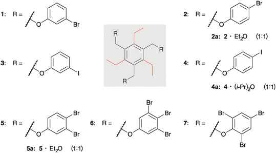 | ||
| Fig. 1 Structures of compounds 1–7 and the composition of the molecular crystals of the solvates 2a, 4a and 5a. | ||
The molecules differ in the type, position and number of halogen atoms attached to the arene rings of the functionalized side-arms. This raises the question of how these structural differences determine the packing behavior of the molecules and the modes of molecular interactions in the crystalline solids.
Results and discussion
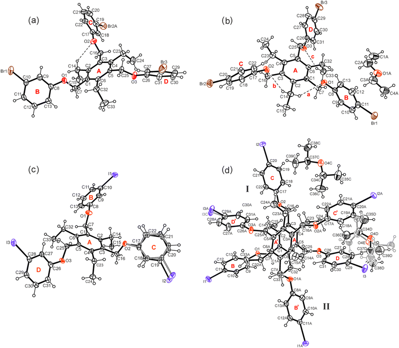
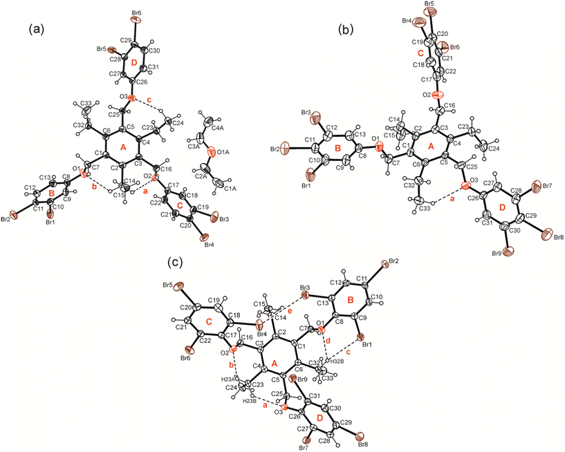
Compounds 1–7 were synthesized by the reaction of 1,3,5-tris(bromomethyl)-2,4,6-triethylbenzene with the corresponding phenol derivative in the presence of potassium carbonate as a base (for details, see Experimental section). Single crystals suitable for X-ray diffraction experiments were obtained by slow evaporation of the solvent from a solution of the respective compound. The crystal and refinement data are summarized in Table S1,† while information regarding non-covalent interactions in the crystals are given in Table S2.† Because of the high content of aromatic building units, the conformation of the molecules can be described by calculation of dihedral angles between the plane fragments designated as A–D in the molecular structures. These geometric parameters together with relevant torsion angles are listed in Table S3.† ORTEP diagrams of the molecular structures including the above-mentioned ring specification are illustrated in Fig. 2 and 3.The X-ray diffraction studies reveal, that six of the examined compounds display common structural features, showing a conformation, in which two of the halogen-substituted phenoxy groups are located on the same side of the central arene ring, while the third group is directed in the opposite direction (aab arrangement, a = above, b = below). In the case of compound 7, the three molecular branches are arranged on one side of the central ring (aaa arrangement).
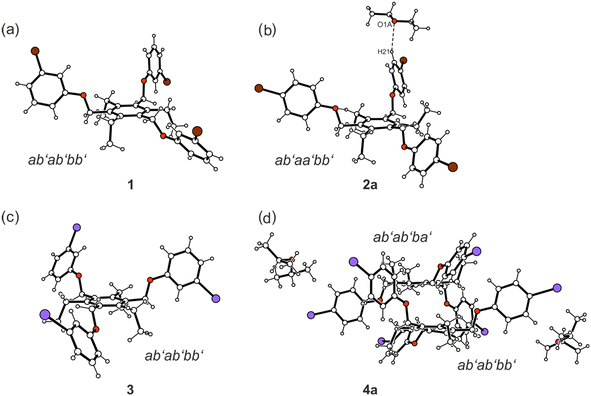
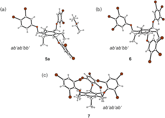
Taking into account the ethyl substituents that can be directed upwards or downwards (marked as a′ = above, b′ = below)9 with respect to the benzene core, four different molecular conformations are observed (see Fig. 4 and 5). In the crystal structures of 1, 3, 4a, 5a and 6, the spatial arrangement of the substituents along the periphery of the central benzene ring follows an ab′ab′bb′ pattern with two of the functionalized side-arms directed to one side of the central benzene ring. The second molecule of 4 in the crystal structure of 4a follows a related ab′ab′ba′ pattern (Fig. 4). The conformation of the molecules found in the inclusion structure of 2a can be defined as ab′aa′bb′, which is also related to the aforementioned conformations. A fully alternating arrangement of phenoxy and ethyl groups in an ab′ab′ab′ pattern is only observed in the crystal of 7 (Fig. 5).
Compounds bearing 3- and 4-halogenophenoxy groups: crystal structures 1, 2a, 3 and 4a
Compound 1 which bears three m-bromophenoxy moieties, crystallizes in the space group P![[1 with combining macron]](https://www.rsc.org/images/entities/char_0031_0304.gif) with one molecule in the asymmetric unit of the cell. The groups labeled B and C in Fig. 2a are located on one side of the central arene ring, while the remaining substituents are oriented to the opposite direction (see also Fig. 4a). The arene rings of the phenoxy groups are inclined at angles of 56.5(2), 83.5(1) and 52.4(1)° with respect to the plane of the central benzene ring. The torsion angles of 169.4(4), −178.3(3) and 175.0(3)° for the Carene–C–O–Carene atomic sequences indicate a slight twisting of these molecular fragments. The crystal of 1 is composed of inversion-symmetric dimers (Fig. 6), in which the molecules are connected by C–H⋯π bonds15 [d(H⋯Cg) 2.73, 2.94 Å]. With the participation of the bromine atoms Br(1) and Br(3), the molecular dimers are linked via type II Br⋯Br contacts16,17 [3.753(1) Å, θ1 = 158.9(2)°, θ2 = 98.1(2)°] resulting in the formation of infinite strands that run parallel to the crystallographic 011 plane. The intermolecular distance of 3.67 Å between the bromine Br(2A) and the center of the arene ring B as well as the bond geometry [∠(C–Br⋯Cg) 162.6°] indicate the presence of a weak Br⋯π contact18 that connects the molecular strands with each other. An excerpt of the packing structure is shown in Fig. 6a.
with one molecule in the asymmetric unit of the cell. The groups labeled B and C in Fig. 2a are located on one side of the central arene ring, while the remaining substituents are oriented to the opposite direction (see also Fig. 4a). The arene rings of the phenoxy groups are inclined at angles of 56.5(2), 83.5(1) and 52.4(1)° with respect to the plane of the central benzene ring. The torsion angles of 169.4(4), −178.3(3) and 175.0(3)° for the Carene–C–O–Carene atomic sequences indicate a slight twisting of these molecular fragments. The crystal of 1 is composed of inversion-symmetric dimers (Fig. 6), in which the molecules are connected by C–H⋯π bonds15 [d(H⋯Cg) 2.73, 2.94 Å]. With the participation of the bromine atoms Br(1) and Br(3), the molecular dimers are linked via type II Br⋯Br contacts16,17 [3.753(1) Å, θ1 = 158.9(2)°, θ2 = 98.1(2)°] resulting in the formation of infinite strands that run parallel to the crystallographic 011 plane. The intermolecular distance of 3.67 Å between the bromine Br(2A) and the center of the arene ring B as well as the bond geometry [∠(C–Br⋯Cg) 162.6°] indicate the presence of a weak Br⋯π contact18 that connects the molecular strands with each other. An excerpt of the packing structure is shown in Fig. 6a.
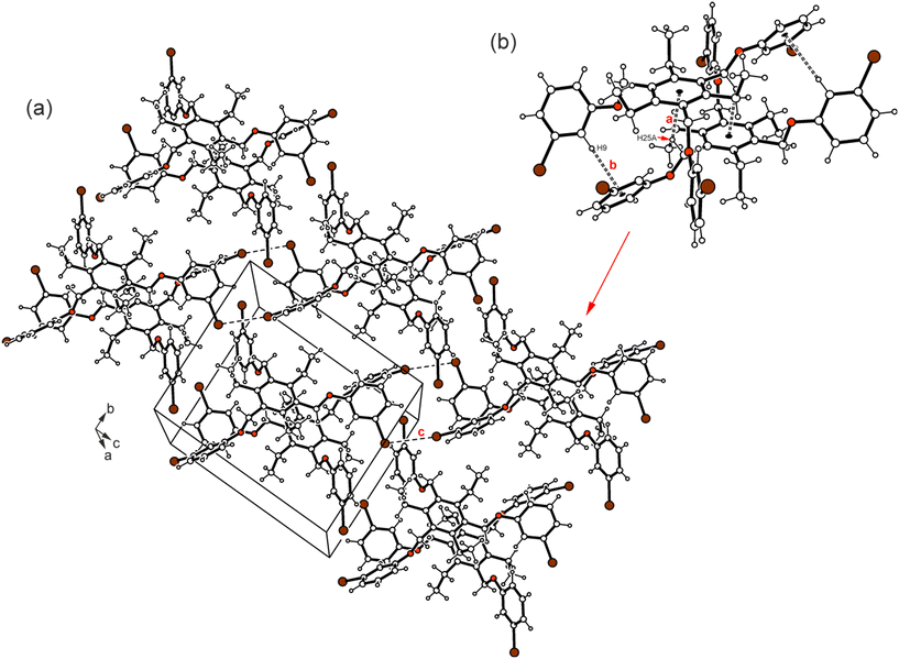 | ||
| Fig. 6 (a) Packing diagram of 1. (b) Molecular dimer with labeling of coordinating atoms (b). Dashed lines represent Br⋯Br interactions and the C–H⋯π interactions are marked by broken double lines. The following interactions are marked: CarylH⋯π (a = 2.94 Å, b = 2.73 Å) and Br⋯Br (c = 3.75 Å); for details see Table S2.† | ||
Crystallization of 2 from diethyl ether yields a 1![[thin space (1/6-em)]](https://www.rsc.org/images/entities/char_2009.gif) :
:![[thin space (1/6-em)]](https://www.rsc.org/images/entities/char_2009.gif) 1 solvate of the space group P
1 solvate of the space group P![[1 with combining macron]](https://www.rsc.org/images/entities/char_0031_0304.gif) with one host molecule and one molecule of solvent in the asymmetric unit of the cell (solvate 2a). In a similar fashion as in the case described before, the 4-bromophenoxy groups in 2a are arranged in an aab fashion with reference to the benzene ring (see Fig. 2b and 4b). The interplanar angles between the phenoxy rings are 88.1(1), 72.0(1) and 59.0(1)°. The oxygen atoms of the host are involved in three intramolecular C–H⋯O bonds19 [d(H⋯O) 2.53–2.64 Å] (see Fig. 2b) that stabilize the conformation.
with one host molecule and one molecule of solvent in the asymmetric unit of the cell (solvate 2a). In a similar fashion as in the case described before, the 4-bromophenoxy groups in 2a are arranged in an aab fashion with reference to the benzene ring (see Fig. 2b and 4b). The interplanar angles between the phenoxy rings are 88.1(1), 72.0(1) and 59.0(1)°. The oxygen atoms of the host are involved in three intramolecular C–H⋯O bonds19 [d(H⋯O) 2.53–2.64 Å] (see Fig. 2b) that stabilize the conformation.
Packing forces cause a considerable twist of the central benzene ring with maximum atomic distances from the least-squares plane of the ring being −0.055(3) for C(4) and 0.057(3) Å for C(5). The oxygen of the solvent molecule is linked via C–H⋯O bonding to the host molecule. A pair of the 1![[thin space (1/6-em)]](https://www.rsc.org/images/entities/char_2009.gif) :
:![[thin space (1/6-em)]](https://www.rsc.org/images/entities/char_2009.gif) 1 host–guest units held together by Cethyl–H⋯O [d(H⋯O) 2.58 Å] and Caryl–H⋯π contacts15 [d(H⋯Cg) 2.92 Å] represents the basic supramolecular entity of the crystal structure (Fig. 7b). These units are further linked via type II Br⋯Br interactions [d(Br⋯Br) 3.522(1) Å, θ1 = 170.1(1)°, θ2 = 94.1(1)°] and C–Br⋯π contacts to form infinite strand-like aggregates extending parallel to the crystallographic 110 plane (Fig. 7a).
1 host–guest units held together by Cethyl–H⋯O [d(H⋯O) 2.58 Å] and Caryl–H⋯π contacts15 [d(H⋯Cg) 2.92 Å] represents the basic supramolecular entity of the crystal structure (Fig. 7b). These units are further linked via type II Br⋯Br interactions [d(Br⋯Br) 3.522(1) Å, θ1 = 170.1(1)°, θ2 = 94.1(1)°] and C–Br⋯π contacts to form infinite strand-like aggregates extending parallel to the crystallographic 110 plane (Fig. 7a).
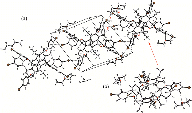 | ||
| Fig. 7 (a) Packing excerpt of 2·Et2O (2a). (b) Dimeric host–guest motif. Dashed lines represent H-bonds and Br⋯Br interactions, dashed double lines Br⋯π contacts. The following interactions are marked: C–H⋯O (d = 2.58 Å, e = 2.63 Å), Br⋯Br (f = 3.52 Å) and C–Br⋯π (g = 3.57 Å); for details see Table S2.† | ||
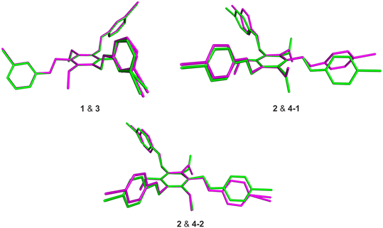
The receptor molecules 3 and 4 represent the iodine-substituted analogs of 1 and 2 and, like these, show similar structural features (for views of some superpositions of the bromo- and iodo-substituted molecules 1 & 3 and 2 & 4, see Fig. 8).
The differences between the molecular structures of 1 and 3 are restricted to the dihedral angles between their aromatic building blocks, so that the geometries of these molecules in their solid state structures are approximately the same. This also explains the similarities in the packing behavior of the molecules.
Also in the crystal of 3, an inversion symmetric dimer the structure of which resembles that found for compound 1, represents the basic supramolecular entity (see Fig. 9 and 10). Within the dimer, the oxygen atom O(2) acts as a trifurcated acceptor for C–H⋯O bonding [d(H⋯O) 2.61–2.62 Å] to the symmetry related molecule. This interaction is assisted by C–H⋯π bonds (Fig. 9b and 10).
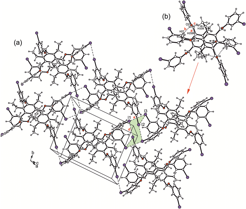 | ||
| Fig. 9 (a) Packing diagram of 3. (b) Structure of the molecular dimer with labeling of atoms involved in H-bond interactions. Dashed lines represent I⋯I interactions, hydrogen bonds are marked as broken lines and C–H⋯π-interactions as broken double lines. The following interactions are marked: C–H⋯O (a = 2.61 Å, b = 2.62 Å, c = 2.61 Å) and I⋯I (d = 3.84 Å, e = 4.08 Å); for details see Table S2.† | ||
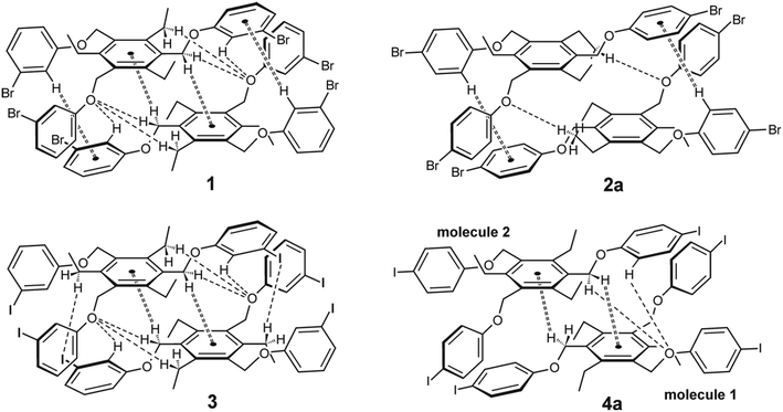 | ||
| Fig. 10 Schematic representation of the dimeric units observed in the crystal structures of 1, 3, 2a and 4a (all molecules display the aab arrangement of the phenoxy units; the arrangement of the ethyl groups is summarized in Table 1). | ||
| Interaction | C–X⋯Y [Å] | C⋯Ya [Å] | C–X⋯Y anglea (°) | Figure | Position of the side-armsb | ||||||||||||||||||||||||||||||||||||||||||||||||||||||||||||||||||||||||||||||||||||||||||||||
|---|---|---|---|---|---|---|---|---|---|---|---|---|---|---|---|---|---|---|---|---|---|---|---|---|---|---|---|---|---|---|---|---|---|---|---|---|---|---|---|---|---|---|---|---|---|---|---|---|---|---|---|---|---|---|---|---|---|---|---|---|---|---|---|---|---|---|---|---|---|---|---|---|---|---|---|---|---|---|---|---|---|---|---|---|---|---|---|---|---|---|---|---|---|---|---|---|---|---|---|
| C–X⋯Br/I | |||||||||||||||||||||||||||||||||||||||||||||||||||||||||||||||||||||||||||||||||||||||||||||||||||
| C–X⋯π | (Y = Br, I or Cg) [Å] | ||||||||||||||||||||||||||||||||||||||||||||||||||||||||||||||||||||||||||||||||||||||||||||||||||
| (X = Br, I) | |||||||||||||||||||||||||||||||||||||||||||||||||||||||||||||||||||||||||||||||||||||||||||||||||||
| a In the case of Br⋯Br or I⋯I interactions following data are given: CA⋯XB and XA⋯CB distances for the CA–XA⋯XB–CB interaction as well as θ1 and θ2 angles (θ1: CA–XA⋯XB angle; θ2: XA⋯XB–CB angle). b Positions of the halogenophenoxy groups (a = above, b = below the plane of the central benzene ring); positions of the ethyl groups (a′ = above, b′ = below). | |||||||||||||||||||||||||||||||||||||||||||||||||||||||||||||||||||||||||||||||||||||||||||||||||||
| 1 | |||||||||||||||||||||||||||||||||||||||||||||||||||||||||||||||||||||||||||||||||||||||||||||||||||
| C–Br⋯Br–C (type II) | 3.753(1) | 5.558(1) | 158.9(1) | Fig. 6 | aab | ||||||||||||||||||||||||||||||||||||||||||||||||||||||||||||||||||||||||||||||||||||||||||||||
| 4.444(1) | 98.1(2) | ab′ab′bb′ | |||||||||||||||||||||||||||||||||||||||||||||||||||||||||||||||||||||||||||||||||||||||||||||||||
| C–Br⋯Cg | 3.677(1) | 5.413(5) | 162.2(6) | ||||||||||||||||||||||||||||||||||||||||||||||||||||||||||||||||||||||||||||||||||||||||||||||||
| 2a | |||||||||||||||||||||||||||||||||||||||||||||||||||||||||||||||||||||||||||||||||||||||||||||||||||
| C–Br⋯Br–C (type II) | 3.522(1) | 5.407(5) | 170.1(1) | Fig. 7 | aab | ||||||||||||||||||||||||||||||||||||||||||||||||||||||||||||||||||||||||||||||||||||||||||||||
| 4.122(5) | 94.1(1) | ab′aa′bb′ | |||||||||||||||||||||||||||||||||||||||||||||||||||||||||||||||||||||||||||||||||||||||||||||||||
| C–Br⋯Cg | 3.572(2) | 5.426(6) | 163.6(2) | Fig. 7 | |||||||||||||||||||||||||||||||||||||||||||||||||||||||||||||||||||||||||||||||||||||||||||||||
| 3 | |||||||||||||||||||||||||||||||||||||||||||||||||||||||||||||||||||||||||||||||||||||||||||||||||||
| C–I⋯I–C (type II) | 3.844(2) | 5.824(2) | 172.6(1) | Fig. 9 | aab | ||||||||||||||||||||||||||||||||||||||||||||||||||||||||||||||||||||||||||||||||||||||||||||||
| 3.713(2) | 70.3(1) | ab′ab′bb′ | |||||||||||||||||||||||||||||||||||||||||||||||||||||||||||||||||||||||||||||||||||||||||||||||||
| C–I⋯I–C (type II) | 4.081(2) | 6.071(2) | 156.8(1) | Fig. 9 | |||||||||||||||||||||||||||||||||||||||||||||||||||||||||||||||||||||||||||||||||||||||||||||||
| 4.721(2) | 94.0(1) | ||||||||||||||||||||||||||||||||||||||||||||||||||||||||||||||||||||||||||||||||||||||||||||||||||
| 4a | |||||||||||||||||||||||||||||||||||||||||||||||||||||||||||||||||||||||||||||||||||||||||||||||||||
| C–I⋯I–C (type II) | 3.771(1) | 5.850(7) | 169.7(2) | Fig. 11 | Molecule 1: aab | ||||||||||||||||||||||||||||||||||||||||||||||||||||||||||||||||||||||||||||||||||||||||||||||
| 4.258(7) | 88.1(2) | ab′ab′ba′ | |||||||||||||||||||||||||||||||||||||||||||||||||||||||||||||||||||||||||||||||||||||||||||||||||
| C–I⋯I–C (type II) | 3.803(1) | 5.882(7) | 168.0(2) | Fig. 11 | Molecule 2: aab | ||||||||||||||||||||||||||||||||||||||||||||||||||||||||||||||||||||||||||||||||||||||||||||||
| 4.312(7) | 88.8(2) | ||||||||||||||||||||||||||||||||||||||||||||||||||||||||||||||||||||||||||||||||||||||||||||||||||
| C–I⋯Cg | 3.625(3) | 5.663(7) | 162.6(2) | Fig. 11 | ab′ab′bb′ | ||||||||||||||||||||||||||||||||||||||||||||||||||||||||||||||||||||||||||||||||||||||||||||||
| C–I⋯Cg | 3.646(3) | 5.566(7) | 149.6(2) | ||||||||||||||||||||||||||||||||||||||||||||||||||||||||||||||||||||||||||||||||||||||||||||||||
The iodine atoms are involved to a higher degree in the connection of the molecular dimers than the bromine atoms in 1. The packing structure of 3 shown in Fig. 9a and the binding parameters listed in Table S3† indicate the participation of iodine atoms I(1), I(2) and I(3) in the formation of I⋯I contacts of type II [d(I⋯I) 3.844(2) Å, θ1 = 172.6 (1)°, θ2 = 70.3(1)°; d(I⋯I) 4.081(2) Å, θ1 = 156.8(1)°, θ2 = 94.0(1)°] with I(1) acting as a bifurcated binding site. Although the packing structures of the two compounds reveal no marked differences, the bromine atoms in 1 induce a strand-like aggregation of the molecular dimers, whereas I⋯I interactions in 3 generate two-dimensional supramolecular networks extending parallel to the crystallographic bc-plane.
Crystal growing of 4 from diisopropyl ether yields colourless plates which proved to be a 1![[thin space (1/6-em)]](https://www.rsc.org/images/entities/char_2009.gif) :
:![[thin space (1/6-em)]](https://www.rsc.org/images/entities/char_2009.gif) 1 solvent inclusion complex (solvate 4a; see Fig. 2d and 4d). The asymmetric unit of the cell contains two crystallographically independent but conformationally different host molecules and two molecules of solvent (guest), one of the latter disordered over two positions (s.o.f. 0.64/0.36). From the crystal structures discussed above, it can be concluded that the formation of pairs of closely nested molecules requires an aab arrangement of their extended substituents. This is also the case in the present crystal structure, in which the dimeric units are formed by the crystallographically non-equivalent molecules (see Fig. 10 and 11). The structure of the strand-like aggregates which results from the connection of the molecular dimers via type II I⋯I [d(I⋯I) 3.771(1) Å, θ1 = 169.2(2)°, θ2 = 88.1(2)°; d(I⋯I) 3.803 (1) Å, θ1 = 168.0(2)°, θ2 = 88.8(2)°] and C–I⋯π interactions [d(I⋯Cg) 3.625(3), 3.646(3) Å, ∠(C–I⋯Cg) 162.6(2)°, 149.6(2)°] corresponds with those observed in the inclusion structure 2a. The presence of a bulky solvent species in 4a induces an extension of the lattice voids occupied by the guest molecules.
1 solvent inclusion complex (solvate 4a; see Fig. 2d and 4d). The asymmetric unit of the cell contains two crystallographically independent but conformationally different host molecules and two molecules of solvent (guest), one of the latter disordered over two positions (s.o.f. 0.64/0.36). From the crystal structures discussed above, it can be concluded that the formation of pairs of closely nested molecules requires an aab arrangement of their extended substituents. This is also the case in the present crystal structure, in which the dimeric units are formed by the crystallographically non-equivalent molecules (see Fig. 10 and 11). The structure of the strand-like aggregates which results from the connection of the molecular dimers via type II I⋯I [d(I⋯I) 3.771(1) Å, θ1 = 169.2(2)°, θ2 = 88.1(2)°; d(I⋯I) 3.803 (1) Å, θ1 = 168.0(2)°, θ2 = 88.8(2)°] and C–I⋯π interactions [d(I⋯Cg) 3.625(3), 3.646(3) Å, ∠(C–I⋯Cg) 162.6(2)°, 149.6(2)°] corresponds with those observed in the inclusion structure 2a. The presence of a bulky solvent species in 4a induces an extension of the lattice voids occupied by the guest molecules.
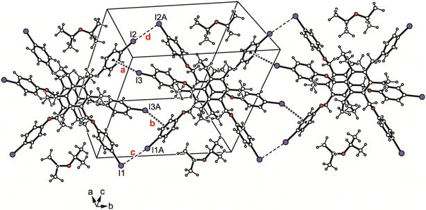 | ||
| Fig. 11 Packing diagram of 4a. Dashed lines represent I⋯I, dashed double lines C–I⋯π interactions. The following interactions are marked: C–I⋯π (a = 3.63 Å, b = 3.65 Å) and I⋯I (c = 3.77 Å, d = 3.80 Å); for details see Table S2.† | ||
It should be mentioned that several crystal structures of 1,3,5-tris[(4-halogenophenoxy)methyl]-2,4,6-triethylbenzene derivatives with fluorine, chlorine, bromine and iodine as the halogen atom have been published by Saha and coworkers.20 In the case of the compounds bearing 4-bromophenoxy and 4-iodophenoxy groups (compounds 2 and 4), other solvent inclusion complexes have been described as those, that are the subject of our work.
Compounds bearing 3,4-dibromo-, 3,4,5- and 2,4,6-tribromophenoxy groups: crystal structures 5a, 6 and 7
Compound 5 crystallized from diethyl ether as colourless plates of the monoclinic space group P21/n with one molecule of receptor (host) and one molecule of solvent (guest) in the asymmetric unit (solvate 5a; see Fig. 3a and 5a). The three 3,4-dibromophenoxy units of the molecule adopt an aab orientation with respect to the plane of the central benzene ring. Taking the ethyl groups into account, the spatial arrangement of substituents along the periphery of the benzene ring follows an ab′ab′bb′ pattern (see Fig. 5a and various superpositions of 5 with other molecules in Fig. S1 and S2†).The tilt angles of the aromatic assemblies B–D with respect to the central aromatic ring A are 79.1(1), 82.3(1), and 62.5(1)°. The three 3,4-dibromophenoxy units adopt an elongated conformation, with torsion angles for their Carene–C–O–Carene sequences being −178.5(3), −168.7(3) and −176.6(3)°.
The oxygen atoms of the host molecule participate in the formation of intramolecular Cethyl–H⋯O bridges [d(H⋯O) 2.43–2.67 Å], as observed in the other crystal structures discussed here. Within the host–guest entity the guest molecule is involved only in a C–H⋯π contact [d(H⋯Cg) 2.82 Å], whereas the O atom of the ether molecule is excluded from linkage.
Corresponding to the high proportion of bromine atoms, the crystal structure is dominated by Br⋯Br interactions of type I [d(Br⋯Br) 3.476(4) Å; θ1 = θ2 = 153.1°] and type II [d(Br⋯Br) 3.443(4) Å; θ1 = 166.1°, θ2 = 108.5°], involving Br(5) and Br(2) and Br(6) atoms, respectively. In addition, the host molecules are weakly cross-linked via C–H⋯Br (ref. 21) [d(H⋯Br) 3.00, 3.08 Å] and C–H⋯π bonds [d(H⋯O) 2.76–2.96 Å] (see Fig. 12).
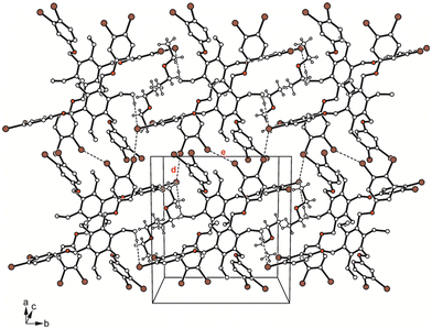 | ||
| Fig. 12 Packing diagram of 5a. Dashed lines represent Br⋯Br and C–H⋯Br interactions. The following interactions are marked: Br⋯Br (d = 3.44 Å, e = 3.48 Å); for details see Table S2.† | ||
Crystallization of 6 from diisopropyl ether yields colourless blocks of the monoclinic space group C2/c with one host molecule and one molecule of solvent in the asymmetric unit of the cell. Because of the highly diffuse nature of the electron density associated with the solvent species, the SQUEEZE routine of the PLATON program was used to create a modified data set, in which the contribution of the disordered molecule to the structure amplitudes is eliminated (see Experimental section). Thus, the final structure model was refined without the solvent. The solvent accessible volume of 6 estimated by PLATON is 667.1 Å3, which represents 8.6% of the cell volume (7764.5 Å3). In the crystal structure the 3,4,5-tribromophenoxy moieties of the receptor adopt an aab arrangement (see Fig. 3b and 5b) and inclination angles of 89.3(2), 84.0(1) and 64.6(1)° with reference to the plane of the central arene ring. The crystal structure is constructed of molecular dimers held together by Br⋯Br, C–H⋯O and C–H⋯π bonds, as shown in Fig. 13. These structure units are further linked by type I and type II Br⋯Br interactions as well as Br⋯π contacts to form a three-dimensional supramolecular network. The packing diagram illustrated in Fig. 13 reveals that the included guests are located in channel-like lattice voids extending along the crystallographic b-axis.
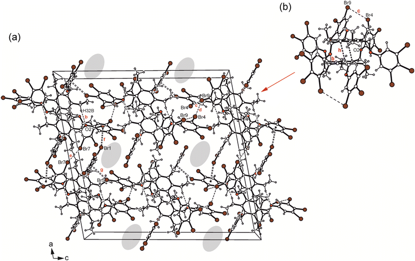 | ||
| Fig. 13 (a) Packing diagram viewed down the crystallographic b-axis and (b) structure motif of 6 including the labeling of atoms involved in non-covalent bonding. Dashed lines represent hydrogen bonds and Br⋯Br interactions, dashed double lines C–Br⋯π contacts. In (a) the positions of the disordered solvent molecules are marked by colour highlighting. The following interactions are marked: C–H⋯O (b = 2.57 Å), Br⋯Br (c = 3.68 Å, d = 3.54 Å, e = 3.51 Å) and C–Br⋯π (f = 3.42 Å, g = 3.39 Å); for details see Table S2.† | ||
Compound 7 was found to crystallize in the monoclinic system (space group P21/n) with one molecule in the asymmetric part of the unit cell. The three 2,4,6-tribromophenoxy moieties are located on one side of the central arene ring (aaa arrangement), whereas the ethyl groups are oriented to the opposite side (ab′ab′ab′; see Fig. 5c). Intramolecular steric interactions caused by the ortho-bromine atoms and the extent of intramolecular non-covalent bonding generate an irregular, strongly distorted molecular geometry, in which the aromatic rings B–D are inclined at angles of 33.0(1), 44.2(1) and 57.2(1)° with regard to the plane of the central benzene ring (A). The molecular structure depicted in Fig. 3c reveals that the conformation is stabilized by three intramolecular C–H⋯O bonds, in which the ethyl hydrogen atoms H(23A) and H(23B) are connected with O(2) and O(3) [d(H⋯O) 2.35, 2.45 Å, ∠(C–H⋯O) 130, 131°], while H(32B) acts as a bifurcated donor for H-bond formation with O(1) and Br(1) [d(H⋯O) 2.43 Å, ∠(C–H⋯O) 130°; d(H⋯Br) 2.89 Å, ∠(C–H⋯Br) 146°]. The intramolecular distance of 3.621(2) Å between the bromine atoms Br(3) and Br(4) linked to the rings B and C as well as the bond geometry [θ1 = 141.0(1)°, θ2 = 139.5(1)°] correspond to a type I Br⋯Br interaction. In addition, the bromine atom Br(9) contributes to formation of an intramolecular C–Br⋯π contact [d(Br⋯Cg) 3.734(2) Å] with the central aromatic unit.
The cross-linking of the molecules is dominated by halogen bonds. The connection of the molecules via Br⋯Br [d(Br⋯Br) 3.737(2) Å] and Br⋯O interactions [d(Br⋯O) 3.266(3) Å] involving the bromine atoms Br(8) as a common binding site creates an inversion symmetric structure motif (see Fig. 14; for comparison of the dimeric structure with those observed in the crystal structures of 5a and 6, see Fig. 15), which is further connected by type II Br⋯Br contacts [d(Br⋯Br) 3.784(2) Å, θ1 = 164.2(1)°, θ2 = 101.0(1)°] and C–H⋯Br bonds [d(H⋯Br) 2.89 Å] to form a three-dimensional supramolecular network.
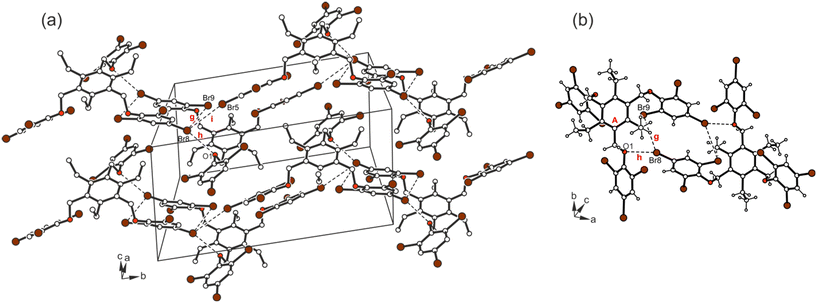 | ||
| Fig. 14 (a) Excerpt of the packing structure and (b) structure motif of 7. Dashed lines represent Br⋯Br and C–Br⋯O interactions. The following interactions are marked: Br⋯Br (g = 3.74 Å, i = 3.78 Å,) and Br⋯O (h = 3.27 Å); for details see Table S2.† | ||
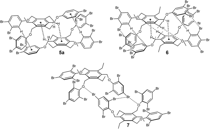 | ||
| Fig. 15 Schematic representation of the dimeric units observed in the crystal structures of 5a, 6 and 7 [molecules 5 and 6 display the aab arrangement of the phenoxy units (the arrangement of the ethyl groups is summarized in Table 2), whereas those of 7 display the fully alternating arrangement (ab′ab′ab′) of the phenoxy and ethyl groups]. | ||
| Interaction | C–Br⋯Y [Å] | C⋯Ya [Å] | C–Br⋯Y anglea (°) | Figure | Position of the side-armsc | ||||||||||||||||||||||||||||||||||||||||||||||||||||||||||||||||||||||||||||||||||||||||||||||
|---|---|---|---|---|---|---|---|---|---|---|---|---|---|---|---|---|---|---|---|---|---|---|---|---|---|---|---|---|---|---|---|---|---|---|---|---|---|---|---|---|---|---|---|---|---|---|---|---|---|---|---|---|---|---|---|---|---|---|---|---|---|---|---|---|---|---|---|---|---|---|---|---|---|---|---|---|---|---|---|---|---|---|---|---|---|---|---|---|---|---|---|---|---|---|---|---|---|---|---|
| C–Br⋯Y | |||||||||||||||||||||||||||||||||||||||||||||||||||||||||||||||||||||||||||||||||||||||||||||||||||
| C–Br⋯π | |||||||||||||||||||||||||||||||||||||||||||||||||||||||||||||||||||||||||||||||||||||||||||||||||||
| (Y = O, Br, Cg, C) | |||||||||||||||||||||||||||||||||||||||||||||||||||||||||||||||||||||||||||||||||||||||||||||||||||
| a In the case of Br⋯Br or I⋯I interactions following data are given: CA⋯XB and XA⋯CB distances for the CA–XA⋯XB–CB interaction as well as θ1 and θ2 angles (θ1: CA–XA⋯XB angle; θ2: XA⋯XB–CB angle). b For C–X⋯π interactions the center of an aromatic ring or an individual carbon atom of the ring was chosen an the acceptor. c Positions of the halogenophenoxy groups (a = above, b = below the plane of the central benzene ring); positions of the ethyl groups (a′ = above, b′ = below). | |||||||||||||||||||||||||||||||||||||||||||||||||||||||||||||||||||||||||||||||||||||||||||||||||||
| 5a | |||||||||||||||||||||||||||||||||||||||||||||||||||||||||||||||||||||||||||||||||||||||||||||||||||
| C–Br⋯Br–C (type II) | 3.443(1) | 5.303(4) | 166.1(1) | Fig. 12 | aab | ||||||||||||||||||||||||||||||||||||||||||||||||||||||||||||||||||||||||||||||||||||||||||||||
| 4.427(4) | 108.5(1) | ab′ab′bb′ | |||||||||||||||||||||||||||||||||||||||||||||||||||||||||||||||||||||||||||||||||||||||||||||||||
| C–Br⋯Br–C (type I) | 3.476(1) | 5.240(4) | 153.1(1) | Fig. 12 | |||||||||||||||||||||||||||||||||||||||||||||||||||||||||||||||||||||||||||||||||||||||||||||||
| 6 | |||||||||||||||||||||||||||||||||||||||||||||||||||||||||||||||||||||||||||||||||||||||||||||||||||
| C–Br⋯Br–C (type I) | 3.511(1) | 5.247(1) | 150.7(1) | Fig. 13 | aab | ||||||||||||||||||||||||||||||||||||||||||||||||||||||||||||||||||||||||||||||||||||||||||||||
| ab′ab′bb′ | |||||||||||||||||||||||||||||||||||||||||||||||||||||||||||||||||||||||||||||||||||||||||||||||||||
| C–Br⋯Cg | 3.417(2) | 5.053(6) | 142.6(1) | Fig. 13 | |||||||||||||||||||||||||||||||||||||||||||||||||||||||||||||||||||||||||||||||||||||||||||||||
| C–Br⋯Cb | 3.392(2) | 5.180(6) | 156.4(1) | Fig. 13 | |||||||||||||||||||||||||||||||||||||||||||||||||||||||||||||||||||||||||||||||||||||||||||||||
| 7 | |||||||||||||||||||||||||||||||||||||||||||||||||||||||||||||||||||||||||||||||||||||||||||||||||||
| C–Br⋯Br–C (type II) | 3.784(2) | 5.639(4) | 164.2(1) | Fig. 14 | aaa | ||||||||||||||||||||||||||||||||||||||||||||||||||||||||||||||||||||||||||||||||||||||||||||||
| 4.547(4) | 101.0(1) | ab′ab′ab′ | |||||||||||||||||||||||||||||||||||||||||||||||||||||||||||||||||||||||||||||||||||||||||||||||||
| C–Br⋯Br–C (type I) | 3.621(2) | 5.210(4) | 139.5(1) | ||||||||||||||||||||||||||||||||||||||||||||||||||||||||||||||||||||||||||||||||||||||||||||||||
| 5.228(4) | 141.0(1) | ||||||||||||||||||||||||||||||||||||||||||||||||||||||||||||||||||||||||||||||||||||||||||||||||||
| C–Br⋯O | 3.266(2) | 5.069(4) | 157.1(1) | Fig. 14 | |||||||||||||||||||||||||||||||||||||||||||||||||||||||||||||||||||||||||||||||||||||||||||||||
Hirshfeld surface analysis
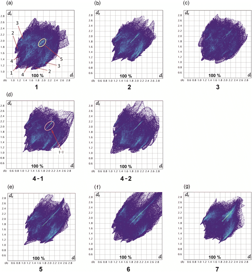
Hirshfeld surfaces22 represent an effective way to gain insight in the packing behavior of molecules in the crystalline state. In order to visualize quantitatively the different types of intermolecular interactions (hydrogen bonding, halogen based interactions, C–H⋯π contacts, etc.) two-dimensional fingerprint plots,23,24 derived from Hirshfeld surfaces, were prepared by using the CrystalExplorer program (Version 21.5).25 In these plots the distance de (distance of the Hirshfeld surface from the nearest nucleus outside the surface) is plotted against di (the corresponding distance to the nearest nucleus inside the surface).The fingerprint plots of compounds 1–7 are displayed in Fig. 16, while information on the percentages of the various contacts are illustrated in Fig. 17 and S3–S10.†
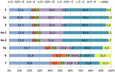 | ||
| Fig. 17 Relative contributions (in %) of different types of intermolecular interactions in the crystal structures of 1–7. | ||
Compound 1 and its iodine substituted analogue 3 show similarities regarding the molecular arrangement in their solid state structures. These structural similarities are also reflected by the two-dimensional fingerprint plots showing nearly identical contributions of the different types of intermolecular interactions in their crystal structures (Fig. 16a and c and 17, S3 and S5†). Due to the high content of hydrogen atoms in the crystal structures, the fingerprint plots are dominated by H⋯H interactions (peak 1 in Fig. 16a) comprising 41.2% (1) and 40.9% (3) of the Hirshfeld surface. In the fingerprint plot for 1 peak 2 represents C⋯H contacts (C–H⋯π contacts) which comprises 24.0% of the surface. The H⋯Br/Br⋯H (peak 3), H⋯O/H⋯O (peak 4) and X⋯X contacts (peak 5) make up 22.3%, 5.2% and 2.2% of the surface, respectively. For compound 3, the relative contributions of the H⋯C, H⋯X (X = I), H⋯O and X⋯X contacts are 23.4%, 22.7%, 4.9% and 2.5% (see Fig. S5†).
The 2D-fingerprint plots of 2 (Fig. 16b and S4†) exhibit similarities to 1, which are reflected by nearly identical values for the different kinds of interactions, in which H⋯H contacts appear as the largest region (44.1%) with a high concentration at de = di ≈ 1.2 Å. The relative contributions of the H⋯C, H⋯X (X = Br), H⋯O and X⋯X contacts are 23.7%, 20.9%, 5.8%, 2.6% (see Fig. S4†). Nevertheless, the plots display differences. The fingerprint plot of 2 reveals three diffuse blue tails of points at the upper right (di = 2.4–2.8 Å), which indicates a non-optimal packing of molecules.
For the structure 4, there are two crystallographically independent molecules in the asymmetric part of the unit cell. Thus, we have produced two fingerprint plots for the molecules (Fig. 16d, S6 and S7†) which are very similar and dominated by H⋯H interactions making up 43.5% and 44.5% of the surface. The peaks at de + di ≈ 1.2 + 2.0 Å represent X⋯H/H⋯X contacts (C–H⋯I) with a contribution of 22.9 and 22.8%, respectively. The bright streak along the diagonal of the fingerprint plot are attributed to I⋯I interactions. The regions at de + di ≈ 1.2 + 1.8 Å in the fingerprint plot correspond with C⋯H/H⋯C contacts (C–H⋯π interactions) which comprise 22.3% and 21.8% of the surface. The sum (de + di) ≈ 2.10 Å for H⋯H interactions as well as the diffuse pattern of points at the upper right region of the plots (de = di > 2.7 Å) indicate that the packing is moderately efficient.
The pair of distinct wings at de + di = 1.1 + 1.9 Å in the 2D fingerprint plot of 5 (Fig. 16e) are attributed to contacts Br⋯H/H⋯Br with a 34.7% participation on the surface of Hirshfeld. Fig. S8† shows a streak along the plot diagonal at di + de > 1.75 + 1.75 Å, so it can be concluded that the Br⋯Br interactions (6.2%) are relatively strong. Furthermore, the plot is characterized by two sharp features (de + di = 1.7 + 1.1 Å) for C⋯H/H⋯C contacts (15.8%) which represent C–H⋯π interactions. Finally, this analysis shows that the O⋯H/H⋯O (4.3%) and C⋯C contacts (0.2%) have the smallest contribution on the Hirshfeld surface.
As mentioned above, the crystal structure of 6 contains a highly disordered solvent species which could not be modeled to an acceptable level. Thus the SQUEEZE routine of the PLATON program was used to eliminate the disordered molecule from the crystal structure, so that the lattice voids create a region of points with high de and di values (>2.8 Å) in the two-dimensional fingerprint plot (Fig. 16f and S9†).26,27 Unlike 1–5, due to the high content of bromine atoms the Hirshfeld surface of compound 6 is dominated by Br⋯H/H⋯Br and Br⋯Br contacts which make up 41.8% and 12.7% of the Hirshfeld surface. The two-dimensional fingerprint plot features a bright sharp streak on the diagonal of the plot starting from de = di ≈ 1.85 Å and extending to the upper right of the plot (dmaxe > 2.7 Å), indicating the presence of Br⋯Br contacts.
Also in compound 7 which represents an isomer of 6, halogen based contacts provide the largest contribution to the Hirshfeld surface with 39.8% for Br⋯H/H⋯Br and 9.7% Br⋯Br interactions (Fig. 17 and S10†). The first are represented by two space related spikes with de + di = 1.75 + 1.05 Å indicating a strong interpenetration of van der Waals radii of the atoms involved. The Br⋯Br contacts are represented by a sharp streak along the diagonal of the fingerprint plot. According to the presence of nine bromine atoms in compounds 6 and 7, the distribution of contacts of different types present in their crystal structures clearly reveals a strong increase of halogen based interactions at the expense of H⋯H-contacts, which account for 16.5% and 11.5%, respectively. Other contacts, i.e. O⋯H/H⋯O (3.5%) and C⋯C (1.5%) contribute less to the Hirshfeld surfaces. Hydrogen bonds of the C–H⋯O type are represented by a pair of symmetrical sharp spikes in the region de + di ≈ 2.72 Å of the fingerprint plot.
Consequently, the analysis of the contacts for compounds 6 and 7 suggests that in both cases halogen based interactions are the driving force in molecular arrangement and crystal packing formation.
Conclusion
The crystal structures of the tripodal triethylbenzene-based compounds 1–7, bearing phenoxy groups substituted by one to three halogen atoms, are characterized by the presence of inversion-symmetric dimers, which are built differently for compounds 1–6 than for 7, the only compound with ortho-substituted halogenophenoxy groups. Compounds 1–6 show a pronounced tendency to form pairs of closely nested molecules which are held together by weak C–H⋯O type hydrogen bonds and/or C–H⋯π arene contacts. Obviously, the formation of such compact structural units enforces a molecular geometry with an aab orientation of the halogenophenoxy groups with reference to the plane of the central arene ring. The crystal structures of these compounds are characterized by a strand-like association of the molecular dimers via type II Hal⋯Hal interactions (Hal = Br or I) which in the case of the solvent inclusion structures 2a and 4a are assisted by Hal⋯π contacts. A comparative analysis of the crystal structures of 1, containing 3-bromophenoxy groups, and its iodine-substituted analogue 3 reveals similarities regarding the packing and coordination behavior of the molecules. Structural similarities are also evident from the solvent inclusion structures of compounds 2 and 4, bearing 4-bromo- and 4-iodophenoxy units, respectively, as is reflected by the space group symmetries and the cell parameters. Compared with the diethyl ether solvate 2a, the increased steric demand of the solvent species in 4a (diisopropyl ether) induces an extension of the lattice voids occupied by the guest molecules, but leaves the structure of the host lattice unaffected.In the crystal structure of the 2,4,6-tribromophenoxy-functionalized derivative 7, which represents a structure isomer of 6, the molecule adopts a conformation with an alternating orientation of aryloxy and ethyl substituents above and below the plane of the central benzene ring (ab′ab′ab′ arrangement). Although this geometry prevents the formation of molecular dimers of the structure mentioned before, the crystal of this compound is constructed of inversion symmetric structure motifs, in which bromine atoms act as bifurcated binding sites for Br⋯Br and Br⋯O interactions. These structure units are further connected by Br⋯Br contacts to form strand-like supramolecular aggregates.
Experimental section
3-Bromo-, 3-iodo-, 4-bromo-, 4-iodo-, 3,4-dibromo-, 3,4,5-tribromo- and 2,4,6-tribromophenol were prepared according to the reported procedures.28 Compounds 1, 3 and 5–7 represent new compounds, whereas 2 and 4 are literature known.20General procedure for the synthesis of compounds 1–7
The corresponding halogenosubstituted phenol (3.0 eq.) was dissolved in dry acetone and stirred with the equimolar amount of potassium carbonate under reflux for one hour. 1,3,5-Tris(bromomethyl)-2,4,6-triethylbenzene (1.0 eq.) was dissolved in the same volume of dry acetone and added dropwise over 30 minutes to the refluxing mixture, which was then refluxed for an additional three hours. Afterwards the solvent was removed under reduced pressure, water and chloroform were added and the phases were separated. The aqueous phase was extracted with chloroform and the combined organic phases were washed with water and dried over sodium sulfate. The solvent was removed under reduced pressure and the corresponding crude product crystallized from diisopropyl ether or hexane.Single crystal X-ray diffraction
Crystals suitable for X-ray diffraction were obtained by slow evaporation of the solvent at room temperature. The collection of crystal data was performed on a IPDS-2T diffractometer (Stoe & Cie, 2009) at 123–203 K with MoKα radiation (λ = 0.71073 Å). Software for data collection and cell refinement was X-AREA29 and for data reduction X-RED.29 Reflections were corrected for background, Lorentz and polarization effects. Preliminary structure models were derived by application of direct methods30 and were refined by full-matrix least-squares calculation based on F2 for all reflections.31 All hydrogen atoms were included in the models in calculated positions and were refined as constrained to bonding atoms.In the crystal of 1, the bromine Br2 is disordered in two positions (90![[thin space (1/6-em)]](https://www.rsc.org/images/entities/char_2009.gif) :
:![[thin space (1/6-em)]](https://www.rsc.org/images/entities/char_2009.gif) 10) and was refined using ISOR and SADI restraints. A similar disorder, but including the neighbouring C atom, was found for 4a: C29A/C-I3A/C with an occupancy of 83
10) and was refined using ISOR and SADI restraints. A similar disorder, but including the neighbouring C atom, was found for 4a: C29A/C-I3A/C with an occupancy of 83![[thin space (1/6-em)]](https://www.rsc.org/images/entities/char_2009.gif) :
:![[thin space (1/6-em)]](https://www.rsc.org/images/entities/char_2009.gif) 17. This disorder was fixed at 83 and 17 to reduce the number of free parameters using ISOR, SADI, and EADP and EXYZ restraints for C29A/C. Furthermore, one diisopropyl ether was found in two positions (64
17. This disorder was fixed at 83 and 17 to reduce the number of free parameters using ISOR, SADI, and EADP and EXYZ restraints for C29A/C. Furthermore, one diisopropyl ether was found in two positions (64![[thin space (1/6-em)]](https://www.rsc.org/images/entities/char_2009.gif) :
:![[thin space (1/6-em)]](https://www.rsc.org/images/entities/char_2009.gif) 36), which was also fixed to reduce the number of free parameters. SADI and ISOR were applied. In the structure of compound 3, one of the phenyl rings (C6H4I) is disordered in two positions (76
36), which was also fixed to reduce the number of free parameters. SADI and ISOR were applied. In the structure of compound 3, one of the phenyl rings (C6H4I) is disordered in two positions (76![[thin space (1/6-em)]](https://www.rsc.org/images/entities/char_2009.gif) :
:![[thin space (1/6-em)]](https://www.rsc.org/images/entities/char_2009.gif) 24). Again, SADI, ISOR and EADP were applied.
24). Again, SADI, ISOR and EADP were applied.
Finally, compound 6 was found to crystallize with solvent molecules showing a high mobility. Therefore, its modelling proved to be difficult and a modified hkl file was created using the SQUEEZE routine32 of the PLATON program.33 This resulted in four voids of 7 Å3 each and no electron as well as four voids of 171 Å3 each with 58 electrons. A clear assignment to a specific solvent molecule is not possible. Diisopropyl ether used as the crystallising solvent contains 58 electrons and does not fit an even number of solvent molecule per unit cell.
Geometrical parameters of the noncovalent interactions were calculated with either SHELXL25 or PLATON program.27
Crystallographic data for the structures described in this paper have been deposited with the Cambridge Crystallographic Data Centre as supplementary publication numbers CCDC 2203223 (1), 2203227 (2a), 2203224 (3), 2203226 (4a), 2203229 (5a), 2203228 (6) and CCDC 2203225 (7).
Conflicts of interest
There are no conflicts to declare.References
- For a discussion on 1,3,5-substituted triethylbenzenes as a basis for the design of host molecules, see: G. Hennrich and E. V. Anslyn, Chem. – Eur. J., 2002, 8, 2218–2224 CrossRef CAS.
- For examples of 1,3,5-substituted 2,4,6-triethylbenzene derivatives bearing pyridine-, pyrimidine-, purine-, phenanthroline-, naphthyridine-, quinoline-, pyridinium-, quinolinium-, (cyclo)alkylamino- or oxime-based recognition groups, see: (a) M. Stapf, W. Seichter and M. Mazik, Eur. J. Org. Chem., 2020, 2020, 4900–4915 CrossRef CAS; (b) S. Kaiser, C. Geffert and M. Mazik, Eur. J. Org. Chem., 2019, 2019, 7555–7562 CrossRef CAS; (c) C. Geffert, M. Kuschel and M. Mazik, J. Org. Chem., 2013, 78, 292–300 CrossRef CAS; (d) M. Mazik and C. Geffert, Org. Biomol. Chem., 2011, 9, 2319–2326 RSC; (e) M. Mazik and C. Sonnenberg, J. Org. Chem., 2010, 75, 6416–6423 CrossRef CAS PubMed; (f) M. Mazik, A. Hartmann and P. G. Jones, Chem. – Eur. J., 2009, 15, 9147–9159 CrossRef CAS; (g) M. Mazik and A. Hartmann, J. Org. Chem., 2008, 73, 7444–7450 CrossRef CAS PubMed; (h) M. Mazik and H. Cavga, Eur. J. Org. Chem., 2007, 22, 3633–3638 CrossRef; (i) M. Mazik and H. Cavga, J. Org. Chem., 2006, 71, 2957–2963 CrossRef CAS PubMed; (j) M. Mazik and A. C. Buthe, J. Org. Chem., 2007, 72, 8319–8326 CrossRef CAS PubMed; (k) M. Mazik and A. C. Buthe, Org. Biomol. Chem., 2008, 6, 1558–1568 RSC; (l) M. Mazik, W. Radunz and R. Boese, J. Org. Chem., 2004, 69, 7448–7462 CrossRef CAS; (m) M. Mazik, RSC Adv., 2012, 2, 2630–2642 RSC; (n) M. Mazik, Chem. Soc. Rev., 2009, 38, 935–956 RSC.
- For examples of acyclic receptors with a triethyl-, trimethyl- or trimethoxybenzene core, including imidazole-, benzimidazole-, indole-, pyrrole-, pyrazole- or pyrimidine-based recognition groups, see: (a) M. Mazik and M. Kuschel, Chem. – Eur. J., 2008, 14, 2405–2419 CrossRef CAS PubMed; (b) M. Mazik and S. Hartmann, Beilstein J. Org. Chem., 2010, 6(9) DOI:10.3762/bjoc.6.9; (c) C. Sonnenberg, A. Hartmann and M. Mazik, Nat. Prod. Commun., 2012, 7, 321–326 CrossRef CAS; (d) M. Mazik and H. Cavga, J. Org. Chem., 2007, 72, 831–838 CrossRef CAS PubMed; (e) J.-R. Rosien, W. Seichter and M. Mazik, Org. Biomol. Chem., 2013, 11, 6569–6579 RSC; (f) J. Lippe, W. Seichter and M. Mazik, Org. Biomol. Chem., 2015, 13, 11622 RSC; (g) N. Koch and M. Mazik, Synthesis, 2016, 48, 2757–2767 CrossRef CAS; (h) M. Stapf, W. Seichter and M. Mazik, Acta Crystallogr., Sect. E: Crystallogr. Commun., 2020, 76, 1679–1683 CrossRef CAS PubMed.
- For examples of macrocyclic receptors, see: (a) J. Lippe and M. Mazik, J. Org. Chem., 2013, 78, 9013–9020 CrossRef CAS PubMed; (b) J. Lippe and M. Mazik, J. Org. Chem., 2015, 80, 1427–1439 CrossRef CAS PubMed; (c) F. Amrhein, J. Lippe and M. Mazik, Org. Biomol. Chem., 2016, 14, 10648–10659 RSC; (d) F. Amrhein and M. Mazik, Eur. J. Org. Chem., 2021, 46, 6282–6303 CrossRef; (e) F. Amrhein, A. Schwarzer and M. Mazik, Acta Crystallogr., Sect. E: Crystallogr. Commun., 2021, 77, 233–236 CrossRef CAS.
- For examples of crystalline complexes formed between acyclic receptors and carbohydrates, see: (a) L. Köhler, W. Seichter and M. Mazik, Eur. J. Org. Chem., 2020, 45, 7023–7034 CrossRef; (b) L. Köhler, C. Hübler, W. Seichter and M. Mazik, RSC Adv., 2021, 11, 22221–22229 RSC; (c) M. Mazik, H. Cavga and P. G. Jones, J. Am. Chem. Soc., 2005, 127, 9045–9052 CrossRef CAS.
- For examples of ammonium receptors containing triethylbenzene scaffold, see: (a) J. Chin, J. Oh, S. Y. Jon, S. H. Park, C. Walsdorff, B. Stranix, A. Ghoussoub, S. J. Lee, H. J. Chung, S.-M. Park and K. Kim, J. Am. Chem. Soc., 2002, 124, 5374–5379 CrossRef CAS PubMed; (b) J. Chin, C. Walsdorff, B. Stranix, J. Oh, H. J. Chung, S.-M. Park and K. Kim, Angew. Chem., Int. Ed., 1999, 38, 2756–2759 CrossRef CAS; (c) T. M. Jonah, L. Mathivathanan, A. N. Morozov, A. M. Mebel, R. G. Raptis and K. Kavallieratos, New J. Chem., 2017, 41, 14835–14838 RSC; (d) M. M. Schulze, N. Koch, W. Seichter and M. Mazik, Eur. J. Org. Chem., 2018, 31, 4317–4330 CrossRef; (e) F. Fuhrmann, W. Seichter and M. Mazik, Org. Mater., 2022, 4, 61–72 CrossRef CAS; (f) F. Fuhrmann, E. Meier, W. Seichter and M. Mazik, Acta Crystallogr., Sect. E: Crystallogr. Commun., 2022, 78, 785–788 CrossRef CAS PubMed.
- M. Stapf, W. Seichter and M. Mazik, Chem. – Eur. J., 2015, 21, 6350–6354 CrossRef CAS PubMed.
- (a) T. D. P. Stack, Z. Hou and K. N. Raymond, J. Am. Chem. Soc., 1993, 115, 6466–6467 CrossRef CAS; (b) X. Wang and F. Hof, Beilstein J. Org. Chem., 2012, 8, 1–10 CrossRef CAS PubMed.
- (a) M. Schulze, A. Schwarzer and M. Mazik, CrystEngComm, 2017, 19, 4003–4016 RSC; (b) N. Koch, W. Seichter and M. Mazik, CrystEngComm, 2017, 19, 3817–3833 RSC.
- (a) D. Das and L. J. Barbour, J. Am. Chem. Soc., 2008, 130, 14032–14033 CrossRef CAS; (b) D. Das and L. J. Barbour, Cryst. Growth Des., 2009, 9, 1599–1604 CrossRef CAS; (c) D. Das and L. J. Barbour, Chem. Commun., 2008, 5110–5112 RSC.
- For discussions on “hexa-hosts”, see: (a) S. Chakraborty, R. Dutta, B. M. Wong and P. Ghosh, RSC Adv., 2014, 4, 62689–62693 RSC; (b) S. Chakraborty, M. Arunachalam, R. Dutta and P. Ghosh, RSC Adv., 2015, 5, 48060–48070 RSC; (c) M. Arunachalam, B. N. Ahamed and P. Ghosh, Org. Lett., 2010, 12, 2742–2745 CrossRef CAS PubMed; (d) M. Arunachalam and P. Ghosh, Org. Lett., 2010, 12, 328–331 CrossRef CAS PubMed; (e) M. Arunachalam and P. Ghosh, Chem. Commun., 2011, 47, 6269–6271 RSC; (f) J. V. Gavette, A. L. Sargent and W. E. Allen, J. Org. Chem., 2008, 73, 3582–3584 CrossRef CAS PubMed; (g) N. Koch, W. Seichter and M. Mazik, Tetrahedron, 2015, 71, 8965–8974 CrossRef CAS.
- For reviews on conformational polymorphism, see: (a) A. J. Cruz-Cabeza and J. Bernstein, Chem. Rev., 2014, 114, 2170–2191 CrossRef CAS; (b) A. Nangia, Acc. Chem. Res., 2008, 41, 595–604 CrossRef CAS PubMed.
- Solvate formation is of high interest to different research areas, see for example: U. J. Griesser, The importance of solvates, in Polymorphism: in the Pharmaceutical Industry, ed. R. Hilfiker, Wiley-VCH, Weinheim, Germany, 2006 Search PubMed.
- J. Bauer, S. Spanton, R. Henry, J. Quick, W. Dziki, W. Porter and J. Morris, Pharm. Res., 2001, 18, 859–866 CrossRef CAS.
- For a discussion on C–H⋯π interactions, see: (a) M. Nishio, Phys. Chem. Chem. Phys., 2011, 13, 13873–13900 RSC.
- Type I and type II halogen–halogen interactions are, for example, defined in: (a) V. R. Pedireddi, D. S. Reddy, B. S. Goud, D. C. Craig, A. D. Rae and G. R. Desiraju, J. Chem. Soc., Perkin Trans. 2, 1994, 11, 2353–2360 RSC; (b) F. F. Awwadi, R. D. Willett, K. A. Peterson and B. Twamley, Chem. – Eur. J., 2006, 12, 8952–8960 CrossRef CAS PubMed.
- For reviews on halogen bonding, see: (a) G. Cavallo, P. Metrangolo, R. Milani, T. Pilati, A. Priimagi, G. Resnati and G. Terraneo, Chem. Rev., 2016, 116, 2478–2601 CrossRef CAS; (b) A. Brown and P. D. Beer, Chem. Commun., 2016, 52, 8645–8658 RSC; (c) L. C. Gilday, S. W. Robinson, T. A. Barendt, M. J. Langton, B. R. Mullaney and P. D. Beer, Chem. Rev., 2015, 115, 7118–7195 CrossRef CAS PubMed; (d) A. Mukherjee, S. Tothadi and G. R. Desiraju, Acc. Chem. Res., 2014, 47, 2514–2524 CrossRef CAS PubMed; (e) A. Priimagi, G. Cavallo, P. Metrangolo and G. Resnati, Acc. Chem. Res., 2013, 46, 2686–2695 CrossRef CAS; (f) F. Meyer and P. Dubois, CrystEngComm, 2013, 15, 3058–3071 RSC; (g) P. Metrangolo, F. Meyer, T. Pilati, G. Resnati and G. Terraneo, Angew. Chem., Int. Ed., 2008, 47, 6114–6127 CrossRef CAS PubMed; (h) P. Metrangolo and G. Resnati, Halogen Bonding Fundamentals and Applications, Springer, Berlin, 2008 CrossRef; (i) K. Rissanen, CrystEngComm, 2008, 10, 1107–1113 RSC; (j) P. Metrangolo, H. Neukirch, T. Pilati and G. Resnati, Acc. Chem. Res., 2005, 38, 386–395 CrossRef CAS PubMed; (k) K. Raatikainen and K. Rissanen, CrystEngComm, 2011, 13, 6972–6977 RSC.
- For examples of C–Hal⋯π interactions, see: (a) A. C. Legon, Angew. Chem., 1999, 111, 2850–2880 ( Angew. Chem., Int. Ed. , 1999 , 38 , 2686–2714 ) CrossRef; (b) S. V. Rosokha and K. Kochi, Halogen Bonding Fundamentals and Applications, Springer, Berlin, 2008 Search PubMed; (c) H. Matter, M. Nazaré, S. Güssregen, D. W. Will, H. Schreuder, A. Bauer, M. Urmann, K. Ritter, M. Wagner and V. Wehner, Angew. Chem., 2009, 121, 2955–2960 ( Angew. Chem., Int. Ed. , 2009 , 48 , 2911–2916 ) CrossRef.
- For examples of C–H⋯O hydrogen bonds, see: (a) G. R. Desiraju, Chem. Commun., 2005, 2995–3001 RSC; (b) R. K. Castellano, Curr. Org. Chem., 2004, 8, 845–865 CrossRef CAS; (c) T. Steiner, J. Chem. Soc., Chem. Commun., 1994, 2341–2342 RSC; (d) T. Steiner and G. R. Desiraju, Chem. Commun., 1998, 891–892 RSC; (e) T. Steiner, Chem. Commun., 1997, 727–734 RSC; (f) M. Mazik, A. Hartmann and P. G. Jones, Eur. J. Org. Chem., 2010, 3, 458–463 CrossRef; (g) M. Mazik, D. Bläser and R. Boese, J. Org. Chem., 2005, 70, 9115–9122 CrossRef CAS PubMed; (h) M. Mazik, D. Bläser and R. Boese, Tetrahedron, 1999, 55, 12771–12782 CrossRef CAS; (i) G. R. Desiraju and T. Steiner, The Weak Hydrogen Bond in Structural Chemistry and Biology, Oxford University Press, Oxford, 1999 Search PubMed.
- (a) S. Bhattacharya and B. K. Saha, Cryst. Growth Des., 2012, 12, 169–178 CrossRef CAS; (b) V. G. Saraswatula and B. K. Saha, New J. Chem., 2014, 38, 897–901 RSC.
- For some examples of C–H⋯halogen interaction, see: (a) C. B. Aakeröy, T. A. Evans, K. R. Seddon and I. Pálinkó, New J. Chem., 1999, 23, 145–152 RSC; (b) P. G. Jones and P. Kuś, Z. Naturforsch., B: J. Chem. Sci., 2007, 62, 725–731 CrossRef CAS; (c) P. G. Jones, A. Zemanek and P. Kuś, Acta Crystallogr., Sect. C: Cryst. Struct. Commun., 2007, 63, o73–o76 CrossRef CAS PubMed; (d) M. Mazik, A. C. Buthe and P. G. Jones, Tetrahedron, 2010, 66, 385–389 CrossRef CAS; (e) P. Seidel, W. Seichter, A. Schwarzer and M. Mazik, Eur. J. Org. Chem., 2021, 2021, 2901–2914 CrossRef CAS; (f) P. Seidel, A. Schwarzer and M. Mazik, Eur. J. Org. Chem., 2019, 2019, 1493–1502 CrossRef CAS.
- M. A. Spackman and D. Jayatilaka, CrystEngComm, 2009, 11, 19–32 RSC.
- M. A. Spackman and J. J. McKinnon, CrystEngComm, 2002, 4, 378–392 RSC.
- J. J. McKinnon, M. A. Spackman and A. S. Mitchell, Acta Crystallogr., Sect. B: Struct. Sci., 2004, 60, 627–668 CrossRef.
- S. K. Wolff, D. J. Grimwood, J. J. McKinnon, M. J. Turner, D. Jayatilaka and M. A. Spackman, CrystalExplorer (Version 21.5), University of Western Australia, 2010 Search PubMed.
- F. P. A. Fabbiani, L. T. Byrne, J. J. McKinnon and M. A. Spackman, CrystEngComm, 2007, 9, 728–731 RSC.
- M. J. Turner, J. J. McKinnon, D. Jayatilaka and M. A. Spackman, CrystEngComm, 2011, 13, 1804 RSC.
- (a) K. Pels and V. Dragojlovic, Beilstein J. Org. Chem., 2009, 5, 75–79 CrossRef; (b) J. G. Wilson, Aust. J. Chem., 1987, 40, 1695–1704 CrossRef CAS; (c) H. H. Hodgson, J. Walker and J. Nixon, J. Chem. Soc., 1933, 1053–1056 RSC; (d) B. Liedholm, L. K. Sydnes, T. Greibrokk, T. Norin and L. Mörch, Acta Chem. Scand., 1984, 38b, 877–884 CrossRef; (e) M. Kohn and G. Soltész, Monatsh. Chem., 1925, 46, 245–251 CrossRef; (f) R. D. C. Gallo, K. S. Gebara, R. M. Muzzi and C. Raminelli, J. Braz. Chem. Soc., 2010, 21, 770–774 CrossRef CAS; (g) E. Nölting and T. Stricker, Ber. Dtsch. Chem. Ges., 1887, 20, 3018–3023 CrossRef.
- Stoe & Cie, X-AREA and X-RED, Stoe & Cie GmbH, Darmstadt, Germany, 2009 Search PubMed.
- G. M. Sheldrick, Acta Crystallogr., Sect. A: Found. Adv., 2015, 71, 3 CrossRef PubMed.
- G. M. Sheldrick, Acta Crystallogr., Sect. C: Struct. Chem., 2015, 71, 3 Search PubMed.
- A. L. Spek, PLATON SQUEEZE, Acta Crystallogr., Sect. C: Struct. Chem., 2015, 71, 9–18 CrossRef CAS PubMed.
- A. L. Spek, PLATON, A Multipurpose Crystallographic Tool, University of Utrecht, The Netherlands, 1999 Search PubMed.
Footnote |
| † Electronic supplementary information (ESI) available. CCDC 2203223–2203229. For ESI and crystallographic data in CIF or other electronic format see DOI: https://doi.org/10.1039/d2ce01203k |
| This journal is © The Royal Society of Chemistry 2023 |

