Fabrication of cellulose paper-based counter electrodes for flexible dye-sensitized solar cells†
Hina
Pervaiz
 *a,
Zuhair S.
Khan
a,
Nadia
Shahzad
a,
Ghulam
Ali
a,
Naseem
Iqbal
 a and
Sofia
Javed
 b
b
aU.S.-Pakistan Centre for Advanced Studies in Energy (USPCAS-E), National University of Sciences and Technology (NUST), H-12 Sector, 44000 Islamabad, Pakistan. E-mail: hpervaizphdf19.ces@student.nust.edu.pk
bSchool of Chemical and Materials Engineering (SCME), National University of Sciences and Technology (NUST), Islamabad 44000, Pakistan
First published on 8th December 2022
Abstract
Here, we introduce the synthesis and deposition of organic/inorganic composite ink on cellulose paper using a rapid ultrasonic spray deposition approach that can be incorporated as a counter electrode (CE) in flexible dye-sensitized solar cells (FDSSCs). The composite ink comprised a copper indium sulfide (CuInS2) nanostructure ink and dispersion of poly(3,4-ethylenedioxythiophene)-poly(styrenesulfonate) (PEDOT:PSS) in water. Fabricated counter electrodes are biodegradable, environment-friendly, flexible, and economical and meet the requirements for sustainable green energy. To evaluate the catalytic activities and power conversion efficiencies of DSSCs, the produced CuInS2/PEDOT:PSS composite ink-based CEs were compared with PEDOT:PSS counter electrodes. Cyclic voltammetry studies found that CuInS2/PEDOT:PSS had a greater cathodic charge transfer current density (Jc) (−1.23 mA cm−2). Moreover, it was found that the potential separation values are small, which indicate a stronger catalytic activity than PEDOT:PSS counter electrodes. The observed exchange current density (J0) was 3.98 mA cm−2, while the limiting current density (Jlim) increased to 45.7 mA cm−2, indicating a fast redox diffusion rate of the CuInS2/PEDOT:PSS CE. The photovoltaic performances of CuInS2/PEDOT:PSS and PEDOT: PSS-based DSSC's were measured and determined to be 5.66% and 4.41%, respectively, while the performance of CuInS2/PEDOT:PSS FDSSC composed of cellulose paper was 1.06%.
1. Introduction
As the world is currently facing energy crisis owing to the rapid growth of the global economy, population, urbanization, rising living standards, and exploitation of fossil fuel reserves, the primary matter confronting the planet at the moment is the production of efficient, and affordable energy.1–4 Fossil fuels provide over 80% of the world's energy, although they are exhaustible and emit CO2, a life-threatening environmental hazard and a greenhouse gas that leads to global warming. With the challenging issues of energy insecurity and environmental destruction, the astonishing growth of solar cells owing to their eco-friendly and sustainable features, has attracted interest in the growing demand for clean energy.5–7FDSSCs are an exciting innovation mainly due to tremendous features over the basic DSSC and Si-based modules, including reduced manufacturing cost, ease of processing, functionality, reasonable electrical efficiency, and other aspects.8–14 In a typical DSSC, along with the working electrode (WE) and a redox electrolyte, the counter electrode (CE) also plays a crucial role in determining the overall cell power conversion efficiency.15–18 The DSSC CE performs two essential roles: it supports the electrolyte reduction, which provides uninterrupted electricity generation, and acts as a means of transferring electrons from the outer circuit back to the electrolyte.19,20 For CE to perform its function smoothly, it requires a catalytic material that can promote electrolyte reduction performance while also acting as an effective electron conductor.21 Platinum was chosen as the catalyst of choice in the first built DSSC because it can provide both properties.22,23 Contrarily, the oil refinery, pharmaceutical, and automobile sectors all make extensive use of platinum. Thus, the price of platinum is astronomically high as a result of its tremendous demand. Compared to photovoltaics, Pt is less expensive in all well-established sectors mentioned above as large revenues are generated, lowering its price. However, lowering the cost of DSSC systems requires replacing pricey platinum and transparent conducting oxides with low-cost and high-efficiency materials.18,24 This entails the use of a strong and active catalytic material as well as a conducting substrate with low sheet resistance.25 Several alternatives to Pt have been reported in literature, comprising conducting polymers, oxides, carbon-based materials, and sulfides.4,26–31
Poly-3,4-ethylenedioxythiophene polystyrenesulfonate (PEDOT:PSS) polymer has aroused special interest in the polymer industry due to the high conductivity, catalytic activity, and mechanical flexibility of PEDOT and the nonconductive PSS anion increases the solubility of the PEDOT polymer in organic solvents and water, despite this advantage, the addition of PSS reduce the overall conductive and electrocatalytic behavior towards I3- reduction.32–35 Here, ternary copper indium sulfide nanostructures are shown to play a distinctive role due to their good catalytic activity and stability.36,37 As such, CuInS2/PEDOT:PSS composite is a pronounced aspirant material for CE due to the unique properties of CuInS2, PEDOT, and PSS. In literature, CuInS2/PEDOT:PSS/conductive glass-based counter electrodes fabricated via different deposition approaches have been reported.8 This type of inorganic/organic composition is not fabricated in the paper-based substrate but other kinds of paper photo anodes, counter electrodes, and electrolytes have been reported in the literature, owing to their versatility in data storage, energy storage devices, writing, packing, and hygienic tissues. They are also affordable, thin, bendable, lightweight, and widely accessible, with excellent biocompatibility, and recyclability.38 Paper's intrinsic compliance with printing has allowed the patterning of active inks on paper.39 A clear path for scaling up the production process has been proven on paper using techniques such as blade, slot die, and spray coating.11 Wang Bo and Lei L Kerr reported the first dye-sensitized paper solar cell in 2011. Photo-anode in DSSCs was made with Ni-coated box paper.12 Hu, Liangbing, et al. (2013) found that cellulose nano-fibril nano-paper has better optical properties than ordinary paper. Nano paper is exceptionally transparent and scatters light in the forward direction because of its small nano-fibril size. In this case, the power conversion efficiency was 0.40%. Altering the nano paper during device assembly might boost cell performance. Transparent and conducting nano-fibrous paper can be used in optoelectronic applications.4
Here, we report the Pt metal-free counter electrodes, FDSSCs comprised of standard TiO₂ working electrode on ITO-PET substrate and flexible (organic/inorganic ink) counter electrode on cellulose paper substrate. Further, the synthesis and deposition of organic/inorganic composite ink on cellulose paper by a rapid ultrasonic spray deposition approach are also described which can be used as a flexible counter electrode in FDSSC. The composite ink comprised copper indium sulfide (CuInS2) nanostructures ink and PEDOT:PSS 1.3 wt% dispersion in H2O. Further, the electrocatalytic and photovoltaic measurements were performed to investigate the performance of the devices.
2. Experimental
2.1 Materials
An ITO-coated glass substrate (9 Ω per sq.), ITO-coated PET substrate, copper chloride 2 hydrate (CuCl2·2H2O), indium chloride tetrahydrate (InCl3·4H2O), and PEDOT:PSS 1.3 wt% dispersion in H2O were obtained from Sigma-Aldrich. For preparing the counter electrode, guanidinium thiocyanate (GuSCN), iodine (I2), 4-tert-butylpyridine (C9H13N), 1-methyl-3-propylimidazolium iodide (MPII), lithium perchlorate (LiClO4), lithium iodide (LiI) and acetonitrile for electrolyte preparation, and, polyvinylpyrrolidone (PVP), ethanol, titanium isopropoxide (TTIP) and hydrochloric acid (HCl) for the working electrode were purchased from Sigma-Aldrich. Ethylene glycol (C2H6O2), thiourea (CH4N2S), and acetylacetone were purchased from Merck. For the cellulose substrate, double A4-sized papers were used. N3 dye, which is basically cis-bis(isothiocyanato)bis(2,2′-bipyridyl-4,4′ dicarboxylato) ruthenium(II) was purchased from Sigma-Aldrich and used for the sensitization of the TiO2 photoanode.2.2 Synthesis of CuInS2 nanostructured
The ternary CuInS2 nanoparticles were synthesized by preparing a solution containing 1.70 g and 1.20 g of indium chloride tetrahydrate and copper chloride dehydrate, respectively, in 40 mL of ethylene glycol, as mentioned in previous work.40 The mixture of chlorides in ethylene glycol was stirred for 60 min to obtain their complexes. A separate solution of 2.40 g of thiourea (CH4N2S) in 40 ml of ethylene glycol was prepared in a 50 ml beaker. The mixture was stirred until the solution became clear. After that, the solution of thiourea was added slowly to the prior solution. The final solution was stirred for 2 hours at 180 °C. During this, the color of the solution converted from colorless to pale yellow, brown, and eventually black as the temperature increased. The black solution was then cooled to room temperature, precipitated, and washed with ethanol to obtain the crude product. The product was then vacuum-dried for a few hours at 80 °C. The final product was annealed at 200 °C for 60 min to obtain a suitable phase for further usage.2.3 Fabrication of counter electrodes (CEs)
CuInS2 nanostructured suspension was formed by combining 20 mg CuInS2 powder with 1 mL hexane and 13 mg thiourea with 5 mL ethanol. After that, the liquids were mixed and ultrasonicated for around 60 min, resulting in a homogeneous and stable suspension for future composite inorganic/organic ink synthesis. The suspension was combined with PEDOT![[thin space (1/6-em)]](https://www.rsc.org/images/entities/char_2009.gif) :
:![[thin space (1/6-em)]](https://www.rsc.org/images/entities/char_2009.gif) PSS in a 1
PSS in a 1![[thin space (1/6-em)]](https://www.rsc.org/images/entities/char_2009.gif) :
:![[thin space (1/6-em)]](https://www.rsc.org/images/entities/char_2009.gif) 1 volume ratio. To prepare the stable CuInS2/PEDOT:PSS ink using the ultrasonic spray deposition (USD) technique, the solution was agitated for 2 hours. The electrode surface for deposition was ultrasonically cleaned (deionized water, acetone, and ethanol) ITO-coated glass substrate (2 × 2 cm2) with an active area of 0.5 × 0.5 cm2. A 3 ml syringe was filled with ink and inserted into a syringe pump. To atomize the ink on the substrate, the nozzle was set at a 2 cm distance. Pristine PEDOT:PSS and CuInS2/PEDOT:PSS inks were consumed in the USD process for 3 min at a high power source with an 80 μl min−1 spray rate, and the films were obtained following heat treatment at 120 °C for 3 hours on a hot plate. In DSSCs, the produced films were used as counter electrodes.
1 volume ratio. To prepare the stable CuInS2/PEDOT:PSS ink using the ultrasonic spray deposition (USD) technique, the solution was agitated for 2 hours. The electrode surface for deposition was ultrasonically cleaned (deionized water, acetone, and ethanol) ITO-coated glass substrate (2 × 2 cm2) with an active area of 0.5 × 0.5 cm2. A 3 ml syringe was filled with ink and inserted into a syringe pump. To atomize the ink on the substrate, the nozzle was set at a 2 cm distance. Pristine PEDOT:PSS and CuInS2/PEDOT:PSS inks were consumed in the USD process for 3 min at a high power source with an 80 μl min−1 spray rate, and the films were obtained following heat treatment at 120 °C for 3 hours on a hot plate. In DSSCs, the produced films were used as counter electrodes.
Furthermore, the USD process was carried out on ITO-coated polyethylene terephthalate (PET) and 80–120 mm cellulose paper substrates for FDSSCs using the same parameters, as used for the previously fabricated electrodes. Fig. 1 shows the electrode development process for DSSCs and FDSSCs at different substrates and inks.
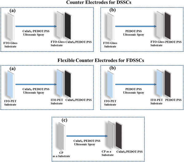 | ||
| Fig. 1 Schematics of counter electrodes prepared for DSSCs and FDSSCs from CuInS2/PEDOT:PSS and PEDOT:PSS inks. | ||
2.4 Assembly of DSSCs
The working electrodes of the cells were fabricated on conducting FTO glass with the doctor blade technique, as mentioned in the literature.41 TiO2 nanoparticles were prepared from TTIP and deposited on cleaned 2 × 2 cm2 ITO glass with a 0.5 × 0.5 cm2 active area. The above-formulated coating was dried at 80 °C for 10 min and calcined at 450 °C for 30 min.The sensitization of the layer was performed in 0.3 M N3 dye solution in ethanol for 24 hours at room temperature and then washed with ethanol and dried in the ambient environment. Further, the working and CE were clamped and separated with a spacer. The electrolyte was prepared with 0.1 M GuSCN, 1.2 M MPII, 0.35 M iodine, and 0.5 M 4-tert-butylpyridine in acetonitrile, which was filled in the cell through the counter electrode hole.
To prepare the paper-based FDSSCs, the working electrode was fabricated on an ITO-PET substrate with a 0.5 × 0.5 cm2 active area and further replaced the CEs with paper-based electrodes, as shown in Fig. S1 (ESI†).
2.5 Measurements and characterization
The crystal structure measurement of CuInS2 nanomaterial was performed on a Bruker D8 ADVANCE X-ray diffractometer (XRD) using CuKα radiations and operating at 40 kV and 30 mA and scanned from 20° < 2θ < 70°. The optical properties, such as absorbance, were measured using a UV-Vis-NIR spectrophotometer. A TESCAN MIRA3 field-emission scanning electron microscopy (FE-SEM) equipped with energy dispersive spectroscopy (EDS) was used to collect the surface and cross-section images and EDS spectra of the particles and films prepared using the ultrasonic spray deposition technique. The photo-current–voltage characteristics of DSSCs were taken using Newport Oriel Keithley PVIV 2400 source meter and solar simulator under illumination of 100 mW cm−2. The active area of DSSCs was 0.25 cm2. The open circuit voltage, short circuit current and fill factor were calculated using current density measurements.Further electrochemical measurements of the counter electrode were performed on a CHI660E electrochemical workstation. Cyclic voltammetry (CV) was performed to measure the redox characteristics of (CuInS2/PEDOT:PSS and PEDOT:PSS) counter electrodes towards tri-iodide reduction by assembling three electrodes at the 100 mV s−1 scan rate where the prepared film acted as the working electrode; Ag/AgCl was used as the reference electrode, and a Pt wire was used as the counter electrode. The electrolyte solution contained 1 mM I2, 10 mM LiI, and 100 mM LiClO4 in acetonitrile.
The electrochemical impedance spectroscopy (EIS) of the DSSC counter was recorded in the frequency range from 100 kHz to 0.1 Hz with dummy cells consisting of two identical electrodes and the same electrolyte, which was used to fabricate the DSSCs. Further, the Tafel polarization curves were obtained using the same dummy cells used for EIS in a potential window of −0.6 V to 0.6 V.
3. Results and discussions
3.1 Investigation on CuInS2 nanoparticles
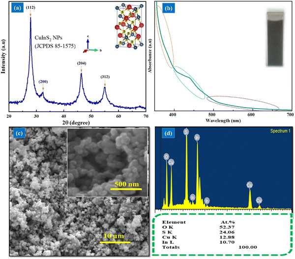
Here, CuInS2 nanoparticles were synthesized in ethylene glycol; usually, CuInS2 nanoparticles are synthesized in olylamine, which is insoluble and immiscible in water. To produce stable ink for the USD process, the miscibility of materials was required. Poly (3,4-ethylenedioxythiophene)-poly (styrenesulfonate) (PEDOT:PSS) 1.3 wt% dispersion in water was used, as such, CuInS2 nanoparticles were synthesized in ethylene glycol to prepare the stable CuInS2/PEDOT:PSS ink.For further investigation, the characterization of the prepared black powder was accomplished. For structural analysis, X-ray diffraction was performed between 20° and 70°, 2θ values. Fig. 2 shows the formation of chalcopyrite CuInS2 nanoparticles without any impurities. The diffraction peaks are located at 27.90°, 32.30°, 45.35°, and 54.90° at 2θ values with (112), (200), (204), and (312) planes of CuInS2 respectively. All the obtained diffraction peaks followed the standard tetragonal chalcopyrite (JCDS 85-1575) crystal phase.
The absorption spectrum of CuInS2 NP dispersion recorded between 350 to 700 nm showed broad absorption in this range. The SEM images show the nano-size spherical shape morphology and homogenous growth of the NPs. EDS results indicate the presence of In, Cu, S, and O elements with approximately 1![[thin space (1/6-em)]](https://www.rsc.org/images/entities/char_2009.gif) :
:![[thin space (1/6-em)]](https://www.rsc.org/images/entities/char_2009.gif) 1
1![[thin space (1/6-em)]](https://www.rsc.org/images/entities/char_2009.gif) :
:![[thin space (1/6-em)]](https://www.rsc.org/images/entities/char_2009.gif) 2 atomic ratios of Cu, In, and S, respectively.
2 atomic ratios of Cu, In, and S, respectively.
The conducting polymer PEDOT:PSS has recently attracted considerable attention as a relatively low-cost CE material for DSSCs owing to its favorable conductivity, remarkable electro-catalytic activity, and good film-forming ability. Despite this, PEDOT:PSS generates a smooth film with a small surface area, as illustrated in Fig. 4(a), which is inadequate in triiodide ion regeneration catalysis. To overcome this limitation, a composite ink composed of CuInS2 nanoparticle ink and PEDOT:PSS 0.3 wt% dispersion in H2O was fabricated and deposited in CEs to increase the active surface area, as shown in Fig. 4(b).
3.2 Catalytic behavior of CuInS2/PEDOT:PSS film
After the investigation of CuInS2 NPs, the inks of CuInS2/PEDOT: PSS and PEDOT:PSS were prepared, as discussed in Section 2.3. The CV of CuInS2/PEDOT: PSS/ITO-Glass-based counter electrode was performed to examine the cathodic current density (Jc) and peak-to-peak potential difference (ΔEpp) because these parameters play an essential role in the investigation of the catalytic behavior of the electrodes. Generally, a higher value of Jc and smaller ΔEpp reveal the better catalytic activity of the material. The cyclic voltammetry curves were obtained on the CuInS2/PEDOT: PSS film using the three electrodes assembly operating at a scan rate of 20 to 120 mV s−1 in a potential window from −1.0 to 1.5 V.In the CV curve of CuInS2/PEDOT:PSS/ITO counter electrode, we obtained two pairs of redox peaks. The positive peaks are termed anodic peaks, which are related to iodine and tri-iodide oxidation, whereas the negative peaks are named cathodic peaks and are associated with tri-iodide reduction. The redox reduction at the cathodic side is defined by eqn (1), and the positive one corresponds to the redox reaction per eqn (2)
| I3− + 2e− ↔ 3I− | (1) |
| 3I2− + 2e− ↔ 2I3− | (2) |
In dye-sensitized solar cells, the reduction reaction of I3− will occur at the counter electrode to complete the circuit conductivity and regenerate the dye molecules, therefore, it is crucial to examine the catalytic ability of I−/I3− at the negative potential side. Further, the ability of a counter electrode for I3− reduction in solar cells relates to the cathodic current density at a more negative potential.
A high value of Jc obtained from the CV measurements showed that the electrodes had increased active surface area and conductivity, which are more favorable for the reduction reaction of I3− and lift the value of Jsc and performance of DSSCs. Fig. S2 (ESI†) shows that the CV curve obtained at 100 mV s−1 scan rate had a higher cathodic current density (−1.23 mA cm−2) and lower peak-to-peak potential difference (0.82 V) value as compared to other CV curves obtained at other scan rates.
3.3 Electrochemical investigation of the counter electrodes
The electrochemical properties of CuInS2/PEDOT:PSS and PEDOT:PSS CEs were examined using the Tafel-polarization plots. At the electrolyte/counter electrode interface, the electron transfer kinetic exchange current density was directly measured from the Tafel polarization curve. As such, J0 of the electron transfer kinetics was measured from the intersection of the linear anodic and cathodic curves at zero over potential, and the limiting current density (Jlim) was recorded from the y-interception of the diffusion zone. Generally, the higher J0 supports the catalytic activity of the electrode and a similarly larger value of Jlim shows a fast redox diffusion rate. The calculated value of J0 for CuInS2/PEDOT:PSS was 3.98 mA cm−2, which was higher than the PEDOT:PSS J0 value of 1.90 mA cm−2. Meanwhile, Jlim was also higher (45.7 mA cm−2).Fig. 3 shows the CV curves of CuInS2/PEDOT:PSS and PEDOT:PSS CEs fabricated on the ITO-glass substrate with iodide species. CuInS2/PEDOT:PSS and PEDOT:PSS CEs produced two pairs of redox peaks, namely, anodic (positive) and cathodic (negative) peaks. The anodic peaks on the CV curves represent iodide and tri-iodide oxidation, while the cathodic peaks represent tri-iodide reduction, as mentioned in the previous section. There is an inverse relation between ΔEpp and the charge transfer rate where a high Jc value reflects a strong catalytic behavior of the CE and a lower value of ΔEpp indicates that the redox reaction occurred smoothly on the CE surface.
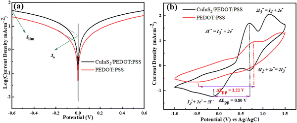 | ||
| Fig. 3 (a) Tafel Polarization Curves and (b) cyclic voltammetry of CuInS2/PEDOT:PSS and PEDOT:PSS counter electrodes. | ||
As shown in Fig. 3, the Jc value of CuInS2/PEDOT:PSS (Jc = −1.23 mA cm−2) is higher compared to the Jc value of PEDOT:PSS CE (Jc = −0.65 mA cm−2), while the ΔEpp value of CuInS2//PEDOT:PSS (ΔEpp = 0.80 V) was lower than that of the PEDOT:PSS CE (ΔEpp = 1.21V).
Both findings (ΔEpp and Jc) for CuInS2/PEDOT:PSS CE indicate an excellent catalytic activity because the composite material has a large redox activity toward I3 and I2 compared to PEDOT:PSS CE. Hence, the CE comprising CuInS2 nanostructure-incorporated PEDOT:PSS rendered a synergistic catalytic effect compared with other CE.
Further, electrochemical impedance spectroscopy (EIS) measurements were performed to study the interfacial electrochemical properties and charge transfer phenomena of the CuInS2/PEDOT:PSS and PEDOT:PSS CEs. Analysis was performed in the frequency range of 100 kHz to 0.1 Hz using the applied open circuit potential. Fig. 4(b) shows Nyquist plots for CuInS2/PEDOT:PSS and PEDOT:PSS having dominant semicircle in the case of CuInS2/PEDOT:PSS, in the presence of interfacial charge transport resistances in the fabricated CuInS2/PEDOT:PSS and PEDOT: PSS-based devices. The Randles circuit model utilized for experimental data fitting is also depicted in Fig. 4(b). The semicircle, visible in the high-frequency range, indicates the charge-transfer resistance (Rct) at the counter electrode/electrolyte interface, further, Rs denotes the sheet resistance, which is mainly due to the resistance of the specific substrate (conducting material) used for the fabrication of electrode and electrolyte diffusion resistance. The values of sheet resistance (Rs), interfacial charge-transfer resistance (Rct), and other parameters are given in Table 1. It is clearly noticed that the interfacial charge transfer resistance Rct of composite CE-based DSSC (175.6 Ω) is lower than the pristine PEDOT:PSS-based DSSCs (329.3 Ω), which elucidated the increased interfacial contact between the electrolyte and CuInS2/PEDOT:PSS.
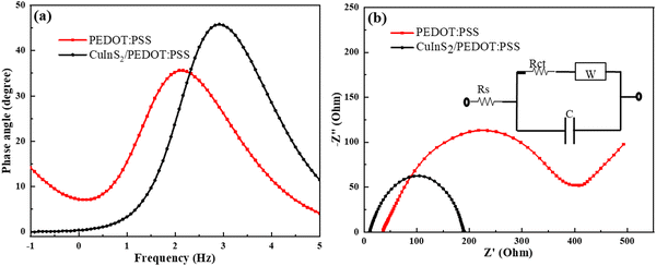 | ||
| Fig. 4 (a) The Bode plot, and. (b) Nyquist plots of CuInS2/PEDOT:PSS and PEDOT:PSS-based dummy cells consisting of two identical electrodes. | ||
| Counter Electrode | R s (Ω) | R ct (Ω) | C (μF) | W | τ (ms) |
|---|---|---|---|---|---|
| CuInS2/PEDOT:PSS | 8.685 | 175.6 | 6.027 | 0.00045 | 0.195 |
| PEDOT:PSS | 32.89 | 329.3 | 19.25 | 0.00736 | 1.324 |
The total internal series resistance is equal to the sum of all these resistances (Rtotal). For DSSCs, made of CuInS2/PEDOT:PSS and PEDOT:PSS, the total internal resistance was 184.5 Ω and 361.6 Ω, respectively. The performance of CuInS2/PEDOT:PSS CE was superior to that of PEDOT:PSS CE. Further, the attained capacitance (C) of the composite-based DSSC was lower than that of the pristine PEDOT: PSS-based DSSC, as such, a higher value of C in the case of PEDOT: PSS-based device was obtained due to the broad absorption from the visible to NIR region, which upsurges the excitation of electrons responsible for the high electron concentration in the TiO2 conduction band.
The existence of the interfacial charge transport resistance can be more inveterate from the phase angle shift in the Bode phase plots shown in Fig. 4(a). The electron relaxation lifetime (τe) was calculated from the peak frequency (fmax) of the Bode phase plots using the relation given in eqn (3),
 | (3) |
It is noteworthy that the obtained electron relaxation lifetime of CuInS2/PEDOT:PSS-based DSSC (0.195 ms) is lower than that of the PEDOT:PSS-based device (1.342 ms). As such, the higher τe of PEDOT: PSS-based DSSC resulted in a longer relaxation lifetime of electrons in the TiO2 conduction band and hence induces higher recombination potentials in the device, which is responsible for the reduced FF in PEDOT: PSS-based DSSC in J–V measurements, as given in Table 2. K Ashok Kumar et al. reported similar electrochemical behavior for cobalt sulfide nanostructures in comparison with the Pt-based DSSCs and reported that cobalt sulfide has been proven to be very effective in catalyzing the redox electrolyte in dye-sensitized solar cells (DSSCs) and exhibits a great potential to replace the traditional noble metal platinum (Pt) counter electrodes in DSSCs.28
| Counter Electrode | V oc (V) | J sc (mA cm−2) | FF | η (%) |
|---|---|---|---|---|
| CuInS2/PEDOT:PSS | 0.76 | 12.96 | 0.57 | 5.66 |
| PEDOT:PSS | 0.77 | 10.52 | 0.54 | 4.41 |
FE-SEM was used to evaluate the surface morphologies of CEs, and the photographs of both CEs composed of PEDOT:PSS and CuInS2/PEDOT:PSS films are depicted in Fig. 4. From the top, it is clearly noticed that the PEDOT:PSS film has a smooth texture, which is detrimental to the electrocatalytic activities (Fig. 5a), and on the other hand, the CuInS2/PEDOT:PSS film had a porous and irregular island-type topography that exhibited dual connectivity, namely, the continuity of CuInS2 nanoparticles in the polymer, and the interconnectivity of pore channels. The nanoparticle continuity is preferable for charge transport within the layer, whereas porosity in the film is favorable for electrolyte permeation and redox pair dissemination in the electrolyte. Furthermore, the porous framework of the CuInS2/PEDOT:PSS film helps to increase the counter electrode's active surface area by providing multiple reactive sites and, therefore, considerably enhancing CE's catalytic performance (Fig. 5b).
 | ||
| Fig. 5 FE-SEM top images of (a) PEDOT:PSS film, (b) CuInS2/PEDOT:PSS film, and (c) cross-sectional view of CuInS2/PEDOT:PSS. | ||
In addition, Fig. 5c depicts the cross-sectional view of the CuInS2/PEDOT:PSS film, which is estimated to be approximately 15 μm thick and exhibited the consistent thickness and high quality of the film, which is favorable for device performance and indicate the uninterrupted ultrasonic spray due to the stable ink on the overall active area of the CE's.
After the FE-SEM analysis, the presence and uniform incorporation of CuInS2 nanostructures inside the PEDOT:PSS film were further investigated using energy-dispersive X-ray spectroscopy (EDS). Fig. 6 describes the PEDOT:PSS and CuInS2/PEDOT:PSS electrode's EDS color mapping. Because, both CuInS2 and PEDOT:PSS ink contain sulfur, the color mapping reveals the highest sulfur concentration. The EDS of a pristine PEDOT:PSS electrode is given in Fig. 6(a). Fig. 6(b) endorses the uniform nanostructure dispersion in the PEDOT:PSS electrode film.
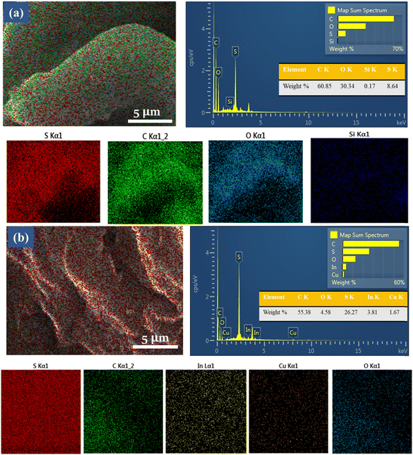 | ||
| Fig. 6 Energy dispersive X-ray Spectroscopy color mapping of (a) PEDOT:PSS and (b) CuInS2/PEDOT:PSS film on the cellulose paper substrate. | ||
To further elucidate the performance of CuInS2/PEDOT:PSS and PEDOT:PSS as CEs in DSSCs, photocurrent density–voltage (J–V) characteristics were measured with a power source under the illumination of 100 mW cm−2. Fig. 7 shows the J–V characteristic curves of DSSCs containing CuInS2/PEDOT:PSS and PEDOT:PSS counter electrodes. The photovoltaic parameters, fill factor (FF), and power conversion efficiency (η), were calculated and all corresponding photovoltaic parameters are summarized in Table 1.
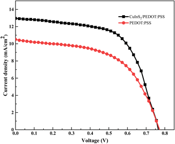 | ||
| Fig. 7 Photocurrent Voltage measurements of DSSCs comprised with TiO2/ITO based photo-anodes with N3 dye sensitization and CuInS2/PEDOT:PSS/ITO, and pristine PEDOT:PSS/ITO-based counter electrodes. | ||
The results show that the DSSC made with CuInS2/PEDOT:PSS CE is more efficient compared to a cell made with the PEDOT:PSS counter electrode. Therefore, the performance of the PEDOT:PSS-based CEs can be significantly enhanced with the addition of CuInS2 nanostructure. These results are consistent with the electrocatalytic measurements; the cell made with CuInS2/PEDOT:PSS CE has smaller Rct and the Rtotal values compared to PEDOT:PSS CE-based DSSCs. Hence, the performance of CuInS2/PEDOT:PSS CE can be seen to be superior than that of PEDOT:PSS CE.
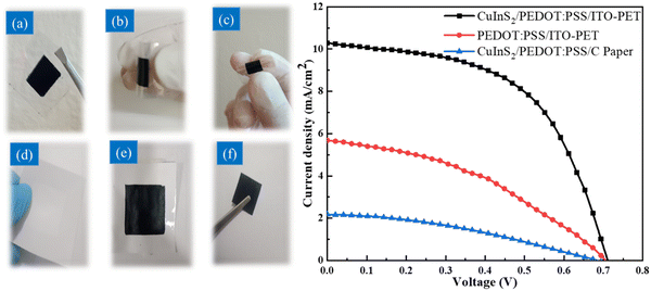
To further examine the benefits of the CuInS2/PEDOT:PSS ink, we manufactured FDSSCs utilizing cellulose papers (CP1–CP3), and the ITO-PET substrate for counter electrodes produced with CuInS2/PEDOT:PSS ink, all flexible CEs used N3-dye/TiO2/ITO-PET flexible photoanodes. The fabrication process was the same one that was used for fabricating counter electrodes, as described in the previous section. The stability of the electrode is a major factor that affects the performance of the device. As such, the paper-based electrodes go through heat tolerance and electrolyte resistibility. To test heat tolerance, the CP electrodes were heated to 100 °C for 1 hour. It was discovered that CP1 electrode shrinkage occurred and that the effect was reduced with paper thickness. To test the percolation of electrolytes into paper electrodes, the electrolyte was poured on top of all the paper surfaces. It was observed that the electrolytes did not seep through to the P3 paper electrode. The P3 paper electrode was considered the most stable and ideal without surface burning, shrinking, and penetration of electrolytes. Fig. 8(a) shows the top view of the electrode surfaces without and with the deposition. Fig. 8(b) illustrates the stability data of the paper electrodes and these flexible electrodes are space-saving, thin, and easy to shape and roll.
Fig. 8 shows the J–V characteristics of three flexible DSSCs made with paper-based counter electrodes. The PCE of the produced FDSSC based on the low-cost hierarchical structured CuInS2/PEDOT:PSS/paper counter electrode is 1.06%, which is comparable to that of the Pt/paper-based DSSC.42 It is worth noting that for the paper-based FDSSCs, FF and V decrease due to the lower transparency, which enhances the recombination rates of the device. The presence of dual valences, Cu (Cu1+ and Cu2+), raises the electro-catalytic activity of the LiI electrolyte, forcing electrons to pair with CB electrons. Furthermore, the presence of dual valence Cu ions causes intermediate trap levels between the conduction and valence bands, lowering the device's Voc (Table 3).
| Counter Electrode | V oc (V) | J sc (mA cm−2) | FF | η (%) |
|---|---|---|---|---|
| CuInS2/PEDOT:PSS/ITO-PET | 0.71 | 10.27 | 0.54 | 3.99 |
| PEDOT:PSS/ITO-PET | 0.70 | 5.68 | 0.39 | 1.56 |
| CuInS2/PEDOT:PSS/C Paper | 0.70 | 2.18 | 0.35 | 1.06 |
4. Conclusion
We demonstrated how inorganic/organic composite ink could be employed as CE material for FDSSCs. The tetragonal CuInS2 NPs and PEDOT:PSS polymer were used to synthesize the composite ink, which was then utilized to prepare an economically efficient CE on ITO-PET and cellulose paper substrates in FDSSCs using an ultrasonic spray deposition technique. The inorganic/organic composite ink-based CEs exhibit higher electro-catalytic performance, as proven by all electrochemical studies, comprising cyclic voltammetry, Tafel polarization, and electrochemical impedance spectroscopy. According to the photovoltaic properties, CuInS2/PEDOT:PSS CE can attain a PCE of 5.66% for DSSCs and 3.99%, 1.06% for CuInS2/PEDOT:PSS/ITO-PET and CuInS2/PEDOT:PSS/cellulose paper CEs, respectively, in FDSSCs. This work introduces a novel concept for the selection of CE materials for the first time on CP in FDSSCs and further expands the usage of composite ink in flexible electronics.Conflicts of interest
There are no conflicts to declare.Acknowledgements
This work was supported by the National University of Sciences and Technology (NUST), the technical support from the Solar Energy Research Lab, and the Advanced Energy Materials Lab.References
- N. Shahzad, Lutfullah, T. Perveen, D. Pugliese, S. Haq, N. Fatima, S. M. Salman, A. Tagliaferro and M. I. Shahzad, Counter electrode materials based on carbon nanotubes for dye-sensitized solar cells, Renewable Sustainable Energy Rev., 2022, 159, 112196, DOI:10.1016/j.rser.2022.112196.
- P. Nandi and D. Das, Morphological variations of ZnO nanostructures and its influence on the photovoltaic performance when used as photoanodes in dye sensitized solar cells, Sol. Energy Mater. Sol. Cells, 2022, 243, 111811, DOI:10.1016/j.solmat.2022.111811.
- A. Omar, M. S. Ali and N. Abd Rahim, Electron transport properties analysis of titanium dioxide dye-sensitized solar cells (TiO2-DSSCs) based natural dyes using electrochemical impedance spectroscopy concept: A review, Sol. Energy, 2020, 207, 1088–1121, DOI:10.1016/j.solener.2020.07.028.
- J. Wu, X. Che, H. C. Hu, H. Xu, B. Li, Y. Liu, J. Li, Y. Ni, X. Zhang and X. Ouyang, Organic solar cells based on cellulose nanopaper from agroforestry residues with an efficiency of over 16% and effectively wide-Angle light capturing, J. Mater. Chem. A, 2020, 8, 5442–5448, 10.1039/c9ta14039e.
- M. Heidariramsheh, M. M. Dabbagh, S. M. Mahdavi and A. Beitollahi, Morphology and phase-controlled growth of CuInS2 nanoparticles through polyol based heating up synthesis approach, Mater. Sci. Semicond. Process., 2021, 121, 105401, DOI:10.1016/j.mssp.2020.105401.
- R. Kumar, V. Sahajwalla and P. Bhargava, Fabrication of a counter electrode for dye-sensitized solar cells (DSSCs) using a carbon material produced with the organic ligand 2-methyl-8-hydroxyquinolinol (Mq, Nanoscale Adv., 2019, 1, 3192–3199, 10.1039/c9na00206e.
- Z. Li, S. Liu, L. Li, W. Qi, W. Lai, L. Li, X. Zhao, Y. Zhang and W. Zhang, In situ grown MnCo2O4@NiCo2O4 layered core-shell plexiform array on carbon paper for high efficiency counter electrode materials of dye-sensitized solar cells, Sol. Energy Mater. Sol. Cells, 2021, 220, 110859, DOI:10.1016/j.solmat.2020.110859.
- Z. Zhang, X. Zhang, H. Xu, Z. Liu, S. Pang, X. Zhou, S. Dong, X. Chen and G. Cui, CuInS2 nanocrystals/PEDOT:PSS composite counter electrode for dye-sensitized solar cells, ACS Appl. Mater. Interfaces, 2012, 4, 6242–6246, DOI:10.1021/am3018338.
- A. H. Javed, N. Shahzad, M. A. Khan, M. Ayub, N. Iqbal, M. Hassan, N. Hussain, M. I. Rameel and M. I. Shahzad, Effect of ZnO nanostructures on the performance of dye sensitized solar cells, Sol. Energy, 2021, 230, 492–500, DOI:10.1016/j.solener.2021.10.045.
- S. Ghannadi, H. Abdizadeh, A. Rakhsha and M. R. Golobostanfard, Sol-electrophoretic deposition of TiO2 nanoparticle/nanorod array for photoanode of dye-sensitized solar cell, Mater. Chem. Phys., 2021, 258, 123893, DOI:10.1016/j.matchemphys.2020.123893.
- N. Shahzad, Z. Shah, M. I. Shahzad, K. Ahmad and D. Pugliese, Effect of seed layer on the performance of ZnO nanorods-based photoanodes for dye-sensitized solar cells, Mater. Res. Express, 2019, 6, 105523, DOI:10.1088/2053-1591/ab3a61.
- A. Hagfeldt, G. Boschloo, L. Sun, L. Kloo and H. Pettersson, Dye-Sensitized Sol. Cells, 2010, 6595–6663 CAS.
- L. Song, P. Chen, Z. Li, P. Du, Y. Yang, N. Li and J. Xiong, Flexible carbon nanotubes/TiO 2/C nanofibrous film as counter electrode of flexible quasi-solid dye-sensitized solar cells, Thin Solid Films, 2020, 711, 138307, DOI:10.1016/j.tsf.2020.138307.
- L. Song, Y. Guan, P. Du, Y. Yang, F. Ko and J. Xiong, Enhanced efficiency in flexible dye-sensitized solar cells by a novel bilayer photoanode made of carbon nanotubes incorporated TiO2 nanorods and branched TiO2 nanotubes, Sol. Energy Mater. Sol. Cells, 2016, 147, 134–143, DOI:10.1016/j.solmat.2015.12.002.
- A. Bist and S. Chatterjee, Review on Efficiency Enhancement Using Natural Extract Mediated Dye-Sensitized Solar Cell for Sustainable Photovoltaics, Energy Technol., 2021, 9, 1–19, DOI:10.1002/ente.202001058.
- K. Wu, S. Liu, Y. Wu, B. Ruan, J. Guo and M. Wu, N-doped W2C derived from polyoxotungstate precursors by pyrolysis along the temperature gradient as Pt-free counter electrode in dye-sensitized solar cells, Sol. Energy Mater. Sol. Cells, 2022, 236, 111503, DOI:10.1016/j.solmat.2021.111503.
- W. Maiaugree, S. Lowpa, M. Towannang, P. Rutphonsan, A. Tangtrakarn, S. Pimanpang, P. Maiaugree, N. Ratchapolthavisin, W. Sang-Aroon, W. Jarernboon and V. Amornkitbamrung, A dye sensitized solar cell using natural counter electrode and natural dye derived from mangosteen peel waste, Sci. Rep., 2015, 5, 1–12, DOI:10.1038/srep15230.
- M. Wu, X. Lin, T. Wang, J. Qiu and T. Ma, Low-cost dye-sensitized solar cell based on nine kinds of carbon counter electrodes, Energy Environ. Sci., 2011, 4, 2308–2315, 10.1039/c1ee01059j.
- F. Bella, A. Sacco, D. Pugliese, M. Laurenti and S. Bianco, Additives and salts for dye-sensitized solar cells electrolytes: What is the best choice?, J. Power Sources, 2014, 264, 333–343, DOI:10.1016/j.jpowsour.2014.04.088.
- Y. Peng, J. Zhong, K. Wang, B. Xue and Y. B. Cheng, A printable graphene enhanced composite counter electrode for flexible dye-sensitized solar cells, Nano Energy, 2013, 2, 235–240, DOI:10.1016/j.nanoen.2012.08.010.
- Q. Zhang, Z. Jin, F. Li, Z. Xia, Y. Yang and L. Xu, First application of CoO nanorods as efficient counter electrode for quantum dots-sensitized solar cells, Sol. Energy Mater. Sol. Cells, 2020, 206, 110307, DOI:10.1016/j.solmat.2019.110307.
- A. Zhao, S. Huang, J. Huang, P. Hu, H. Mao, C. Chen, Y. Li and M. Wei, Nickel foam supported Pt as highly flexible counter electrode of dye-sensitized solar cells, Sol. Energy, 2021, 224, 82–87, DOI:10.1016/j.solener.2021.05.068.
- J. Xia, Q. Wang, Q. Xu, R. Yu, L. Chen, J. Jiao, S. Fan and H. Wu, High efficiency bifacial quasi-solid-state dye-sensitized solar cell based on CoSe2 nanorod counter electrode, Appl. Surf. Sci., 2020, 530, 147238, DOI:10.1016/j.apsusc.2020.147238.
- M. Wu, Y. Wang, X. Lin, N. Yu, L. Wang, L. Wang, A. Hagfeldt and T. Ma, Economical and effective sulfide catalysts for dye-sensitized solar cells as counter electrodes, Phys. Chem. Chem. Phys., 2011, 13, 19298–19301, 10.1039/c1cp22819f.
- M. Wu and T. Ma, Platinum-free catalysts as counter electrodes in dye-sensitized solar cells, ChemSusChem, 2012, 5, 1343–1357, DOI:10.1002/cssc.201100676.
- M. A. K. L. Dissanayake, J. M. K. W. Kumari, G. K. R. Senadeera and H. Anwar, Low cost, platinum free counter electrode with reduced graphene oxide and polyaniline embedded SnO2 for efficient dye sensitized solar cells, Sol. Energy, 2021, 230, 151–165, DOI:10.1016/j.solener.2021.10.022.
- Y. Ko, D. Kim, U. J. Kim and J. You, Vacuum-assisted bilayer PEDOT:PSS/cellulose nanofiber composite film for self-standing, flexible, conductive electrodes, Carbohydr. Polym., 2017, 173, 383–391, DOI:10.1016/j.carbpol.2017.05.096.
- K. Ashok Kumar, A. Pandurangan, S. Arumugam and M. Sathiskumar, Effect of Bi-functional Hierarchical Flower-like CoS Nanostructure on its Interfacial Charge Transport Kinetics, Magnetic and Electrochemical Behaviors for Supercapacitor and DSSC Applications, Sci. Rep., 2019, 9, 1–17, DOI:10.1038/s41598-018-37463-0.
- K. Subalakshmi, K. A. Kumar, O. P. Paul, S. Saraswathy, A. Pandurangan and J. Senthilselvan, Platinum-free metal sulfide counter electrodes for DSSC applications: Structural, electrochemical and power conversion efficiency analyses, Sol. Energy, 2019, 193, 507–518, DOI:10.1016/j.solener.2019.09.075.
- E. Meyer, A. Bede, N. Zingwe and R. Taziwa, Metal sulphides and their carbon supported composites as platinum-free counter electrodes in dye-sensitized solar cells: A review, Materials, 2019, 12, 1980, DOI:10.3390/ma12121980.
- M. Wu, Y. Nan Lin, H. Guo, W. Li, Y. Wang and X. Lin, Design a novel kind of open-ended carbon sphere for a highly effective counter electrode catalyst in dye-sensitized solar cells, Nano Energy, 2015, 11, 540–549, DOI:10.1016/j.nanoen.2014.11.032.
- J. Huang, P. F. Miller, J. C. De Mello, A. J. De Mello and D. D. C. Bradley, Influence of thermal treatment on the conductivity and morphology of PEDOT/PSS films, Synth. Met., 2003, 139, 569–572, DOI:10.1016/S0379-6779(03)00280-7.
- C. P. Lee, C. A. Lin, T. C. Wei, M. L. Tsai, Y. Meng, C. T. Li, K. C. Ho, C. I. Wu, S. P. Lau and J. H. He, Economical low-light photovoltaics by using the Pt-free dye-sensitized solar cell with graphene dot/PEDOT: PSS counter electrodes, Nano Energy, 2015, 18, 109–117, DOI:10.1016/j.nanoen.2015.10.008.
- P. Fu, J. K. Xiao, J. Z. Gong, Y. Zhu, J. A. Yao, Y. F. Zhang, S. G. Wang, Z. D. Lin and F. P. Du, Interfacial enhancement effect of graphene quantum dots on PEDOT:PSS/single-walled carbon nanotubes thermoelectric materials, Synth. Met., 2021, 280, 116861, DOI:10.1016/j.synthmet.2021.116861.
- D. Yoo, J. Kim and J. H. Kim, Direct synthesis of highly conductive poly(3,4-ethylenedioxythiophene):Poly(4-styrenesulfonate) (PEDOT:PSS)/graphene composites and their applications in energy harvesting systems, Nano Res., 2014, 7, 717–730, DOI:10.1007/s12274-014-0433-z.
- S. Xu, N. Cheng, H. Yin, D. Cao and B. Mi, Electrospray preparation of CuInS2 films as efficient counter electrode for dye-sensitized solar cells, Chem. Eng. J., 2020, 397, 125463, DOI:10.1016/j.cej.2020.125463.
- R. Yao, Z. Zhou, Z. Hou, X. Wang, W. Zhou and S. Wu, Surfactant-Free CuInS 2 Nanocrystals: An Alternative Counter- Electrode Material for Dye-Sensitized Solar Cells, ACS Appl. Mater. Interfaces, 2013, 5, 3143–3148, DOI:10.1021/am400031w.
- V. L. Pushparaj, M. M. Shaijumon, A. Kumar, S. Murugesan, L. Ci, R. Vajtai, R. J. Linhardt, O. Nalamasu and P. M. Ajayan, Flexible energy storage devices based on nanocomposite paper, Proc. Natl. Acad. Sci. U. S. A., 2007, 104, 13574–13577, DOI:10.1073/pnas.0706508104.
- J. Li, H. Yang, K. Huang, S. Cao, Y. Ni, L. Huang, L. Chen and X. Ouyang, Conductive regenerated cellulose film as counter electrode for efficient dye-sensitized solar cells, Cellulose, 2018, 25, 5113–5122, DOI:10.1007/s10570-018-1913-1.
- H. Pervaiz, Z. S. Khan, N. Shahzad, N. Ahmed and Q. Jamil, Synthesis and characterization of CuInS2 nanostructures and their role in solar cell applications, Mater. Chem. Phys., 2022, 290, 126602, DOI:10.1016/j.matchemphys.2022.126602.
- A. T. Raghavender, A. P. Samantilleke, P. Sa, B. G. Almeida, M. I. Vasilevskiy and N. H. Hong, Simple way to make Anatase TiO2 films on FTO glass for promising solar cells, Mater. Lett., 2012, 69, 59–62, DOI:10.1016/j.matlet.2011.11.067.
- C. P. Lee, K. Y. Lai, C. A. Lin, C. T. Li, K. C. Ho, C. I. Wu, S. P. Lau and J. H. He, A paper-based electrode using a graphene dot/PEDOT:PSS composite for flexible solar cells, Nano Energy, 2017, 36, 260–267, DOI:10.1016/j.nanoen.2017.04.044.
Footnote |
| † Electronic supplementary information (ESI) available. See DOI: https://doi.org/10.1039/d2cp04358k |
| This journal is © the Owner Societies 2023 |

