Advances in organic microporous membranes for CO2 separation
Yuhan
Wang†
a,
Haifei
Jiang†
ab,
Zheyuan
Guo
a,
Hanze
Ma
a,
Shaoyu
Wang
a,
Hongjian
Wang
a,
Shuqing
Song
a,
Junfeng
Zhang
 b,
Yan
Yin
 b,
Hong
Wu
 a,
Zhongyi
Jiang
 *ac and
Michael D.
Guiver
 *bcd
*bcd
aKey Laboratory for Green Chemical Technology of Ministry of Education, School of Chemical Engineering and Technology, Tianjin University, Tianjin 300072, China. E-mail: zhyjiang@tju.edu.cn
bState Key Laboratory of Engines, School of Mechanical Engineering, Tianjin University, Tianjin 300072, China. E-mail: michael.guiver@outlook.com
cHaiHe Laboratory of Sustainable Chemical Transformations, Tianjin, 300192, China
dNational Industry-Education Platform of Energy Storage, Tianjin University, Tianjin 300072, China
First published on 6th December 2022
Abstract
Carbon emission has become a worldwide concern with global warming and concurrent climate changes. Carbon capture using membrane-based technology offers an effective way to achieve controllable carbon emission and carbon neutrality. During the past decade, organic microporous materials have demonstrated superior physical and chemical properties and triggered a revolution in novel membrane structures. In this Perspective, we focus on progress in advanced organic microporous membranes, with an emphasis on highlighting confined mass transport mechanisms, design principles and representative organic microporous membranes as well as their CO2 separation applications. First, we discuss the abnormal confinement effect in organic microporous membrane channels based on a physical/chemical confined mechanism to understand CO2 molecular transport behavior. Second, we propose three design principles, nano-assembly engineering, reticular engineering, and microenvironment engineering, to construct task-specific membrane structures. Third, we summarize four categories of organic microporous membrane materials, which are polymers of intrinsic microporosity (PIM), graphene oxide (GO), metal–organic framework (MOF) and covalent organic framework (COF). Last, we provide a perspective on the opportunities and major challenges to achieve the transformation from advanced membranes to real-world applications.
Broader contextCarbon neutrality has become a worldwide concern with global warming and concurrent climate changes. As a potential technology for carbon capture, membrane-based separation has been extensively researched from material design to process design. Membranes used for CO2 capture or removal involve multidisciplinary research, such as surface science, materials science, chemistry and chemical engineering. During the past decade, organic microporous materials have demonstrated superior physical and chemical properties and triggered a revolution in novel membrane structures. This Perspective focuses on progress in advanced organic microporous membranes, with an emphasis on highlighting confined mass transport mechanisms, design principles and representative organic microporous membranes as well as their CO2 separation applications. |
1. Introduction
The soaring increase of CO2 emissions from power generation and other industrial activities presents a great challenge for the sustainable development of modern society. According to the data from the National Oceanic and Atmospheric Administration (NOAA), the concentration of atmospheric CO2 has surpassed 420 ppm and has continued on an ascending trend.1 From 2010 to 2020, the average CO2 emission was nearly 35 Gt per year, far exceeding the carrying capacity of the ecological cycle.2 Carbon capture, utilization and storage (CCUS), which integrates technologies to capture, separate, transport and store CO2, is deemed as one feasible strategy to minimize environmental impact. Up until 2021, there were nearly 30 CCS/CCUS demonstration projects in operation around the world, with a CO2 capture and storage capacity of 43 million tons per year, and over 20 projects are under construction.3 With the aid of CCUS, an estimated 14–20% of anthropogenic CO2 emissions may be mitigated, corresponding to a reduction of 120–160 Gt CO2 by 2050.4,5 Carbon capture is the first stage of a CCUS process, and current technologies mainly encompass cryogenic distillation, absorption, adsorption and membrane separation. Different carbon capture processes each have their own particular characteristics and can be applied to different separation tasks, fully considering separation requirements, energy and material consumption, and operating conditions.6 Ammonia absorption is currently the most commonly used carbon capture method due to its high separation selectivity and acceptable energy consumption.7 But for offshore operations, tower-based separation technology will be severely affected by the operating environment, such as wind and waves. Thus, compact membrane separation systems are more convenient and suitable.8,9 Therefore, the development and coupling of different separation technologies is necessary to deal with more complex and difficult decarbonizing sectors in electricity generation, cement production, methane purification and steel production.Membrane separation is receiving widespread attention due to its small physical footprint, scalability, simplicity, environmental friendliness and low energy consumption.10 Central to the process are the membranes themselves, which determine the separation efficiency. In some CO2 separation processes, such as CO2 removal from flue gas, very high gas permeances are required because of the enormous gas flow. However, one of the major challenges is to precisely tune the pore structure to ensure high selectivity without compromising the permeance.11 The so-called permeability/permeance–selectivity trade-off effect12 is negatively affected by the separation of complex, multicomponent mixtures, where conventional single-stage distillation processes are more attractive than complex multiple-membrane cascades, despite the higher energy costs of distillation. Over the past decade, membrane separation has undergone a significant evolution. The progress and innovation of membrane materials has helped to provide new solutions to fundamentally solve some of the trade-off effects. Organic microporous materials are a class of materials with intrinsic pore structure comprising organic components as the main body, for example, polymers of intrinsic microporosity (PIMs),13–15 conjugated microporous polymers (CMPs),16–18 porous aromatic frameworks (PAFs),19 hypercrosslinked polymers (HCP),20 graphene oxide (GO),21 metal organic frameworks (MOFs),22 covalent organic frameworks (COFs),23 and hydrogen-bonded organic frameworks (HOFs).24 Conventional polymer membranes are mostly formed from stacked polymer chain structural segments, and mass transport is achieved by their local motion. In contrast, organic microporous materials have permanent intrinsic pores, providing efficient mass transport channels and thus low resistance. The tailored structure and abundant chemical functionality allow precision membrane design for CO2 separation. Thus, organic microporous materials are deemed as disruptive membrane materials with great development potential.
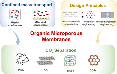
While industrial membranes are still dominated by inorganic molecular sieves and polymers, emerging organic microporous materials have much potential to take the lead. We published two reviews in 2012 and 2016, which focused on high-permeability polymer-based membrane materials.25,26 In this Perspective, we focus on emerging organic microporous membranes and provide insights into the development trend of membranes that can be utilized for CO2 separation. The scope of this Perspective is divided into three sections: mass transport mechanisms, design principles and high-performance membranes, analyzing the mechanism–structure–performance relationship (Fig. 1). Firstly, advanced mass transport mechanisms are the key to achieving high performance membranes. The advancement of membrane materials and structures allows evolution in mass transport behavior. Conventional mass transport mechanisms, including solution-diffusion, molecular sieving, and facilitated transport, are currently inadequate in accurately describing the molecular transport behavior in organic microporous membranes. The emerging confined mass transport mechanism is essential to understand and manipulate the multiple interactions occurring between molecules and nanochannels. Secondly, three design principles are highlighted to construct advanced membrane structures with lower mass transport resistance and higher mass transport rates. Thirdly, we summarize the development status of organic microporous membranes, mainly focusing on those derived from PIMs, GOs, MOFs and COFs. In this part, material characteristics, membrane preparation methods, applications, current opportunities, and challenges are further analyzed. In general, this Perspective focuses on innovation in the field of membranes triggered by new materials and incorporates the concept and thinking of ideal membrane design, which is expected to render new opportunities to optimize the carbon capture process with high energy efficiency and low carbon footprint.
2. Confined mass transport mechanisms
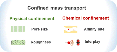
Confined mass transport refers to the mass transport behavior of molecules in a confined space smaller than or equivalent to the mean free path of their molecular motion. With continuous advances in nanotechnology and materials science, membrane separation is undergoing a revolution from dense membranes to porous membranes.27,28 The separation mechanism of dense membranes is mostly adequately described by the solution-diffusion mechanism, but it does not fully consider the influence of pore size, pore structure and guest–membrane interactions, when present (Fig. 2). The novel confined mass transport mechanism is more suitable to describe the selective transport of small molecules at the nanometer or sub-nanometer scale in organic microporous membranes.29 In confined nanochannels, the number of molecules resident within the micropores is greatly reduced. The influence of interactions between the interface and gas molecules is significantly enhanced, even changing the aggregation state of molecules. The mass transport resistance may be dominated by the gas molecule–nanochannel wall interactions rather than intermolecular forces. Confined mass transport behavior plays an important role in both selectivity and permeability of membranes. In this section, we briefly discuss the unique mass transport behavior in nanochannels, and physical and chemical confined mass transport mechanisms. In order to gain a more comprehensive understanding of the mechanism, the discussion in this section is not limited to CO2 molecules, but also involves H2O and CH4.2.1 Unique mass transport behavior in nanochannels
With advances in materials, diverse confined nanochannels have been designed and synthesized, based on one-dimensional (1D) nanotubes, two-dimensional (2D) nanosheets and three-dimensional (3D) crystals. The unique mass transport behavior in nanochannels is observed and analyzed, to gain an understanding of the confined transport effect. Shi and Luebke reported enhanced gas absorption behavior of an ionic liquid (IL) confined in silica slit channels (25–45 Å) by a molecular simulation study.30 On the basis of the smooth and atomistic potential models for silica, the confined IL was calculated to have a 12–31% larger molar volume than the bulk IL at 313–573 K and 1 bar, and the gas absorption of CO2, N2 and H2 was increased by 1.1–3.0 times. Due to the lower IL density near the wall, adsorption and rearrangement of gas molecules occurred at the wall surface, resulting in self-diffusivities being 2–8 times higher than those in the bulk IL. Similar enhancement did not work for water, because it was hydrogen bonded with the IL-rich region, away from the wall. The confinement effect was not only reflected in the adsorption behavior but also in the diffusion behavior. Lu et al.31 used molecular simulation to study the diffusion behavior of a CO2/CH4 mixture in carbon nanotube (CNT) bundles. The results showed that the diffusion behavior is significantly affected by the size of the confined pore. Within the CNTs of diameter less than 1.0 nm, both CO2 and CH4 followed single-file diffusion. Within the CNTs of diameter larger than 1.0 nm, both the molecules followed Fickian diffusion. Dual-mode diffusion was also observed, where single-file diffusion of CO2 occurred in the interstitial sites and Fickian diffusion occurred in the pores. The interaction energies (CO2–CO2 and CO2–CNT) are larger than that of CH4 in all cases, which demonstrates this to be the key factor for the separation of CO2/CH4 (Fig. 3).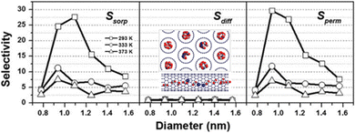 | ||
| Fig. 3 Adsorption selectivity, diffusion selectivity and permeation selectivity of the CO2/CH4 mixture in CNTs. The inset shows atomistic renderings of CNTs examined in this study. Adapted from ref. 31 with permission. Copyright 2016, Taylor & Francis. | ||
Besides the artificial channels, the confinement effect is also observed in natural channels. Sophisticated structures in nature and living organisms exhibit supernormal functions beyond expectation, which also inspires the design of advanced structures. For example, aquaporin (AQP) is considered as an archetypical biological channel, and its biological functions and underlying mechanisms have been widely studied. Lee and Jap revealed the relationship between highly selective water penetration and the structure of AQP (Fig. 4).32 Besides the functionality of a water-channel, the function as facilitator for membrane transport of CO2 has been examined and gradually recognized. AQP embedded in the lipid bilayer provides important channels for the otherwise tight and low-permeability membrane, for which the permeability could reach 120![[thin space (1/6-em)]](https://www.rsc.org/images/entities/char_2009.gif) 000 molecules per second per AQP subunit.33,34 It was indicated that CO2 transport depends on both the monomers and the central pore formed by the tetramer. With an ideal pore size of 0.3 nm, the amino-acid residues provide a delicate physicochemical microenvironment for accommodating CO2. In addition, the high water content in AQP allows CO2 transport in the form of HCO3−. Although there is still some ambiguity regarding the underlying transport mechanism, the unique structure of AQP offers rich inspiration for the design of advanced mass transport channels.
000 molecules per second per AQP subunit.33,34 It was indicated that CO2 transport depends on both the monomers and the central pore formed by the tetramer. With an ideal pore size of 0.3 nm, the amino-acid residues provide a delicate physicochemical microenvironment for accommodating CO2. In addition, the high water content in AQP allows CO2 transport in the form of HCO3−. Although there is still some ambiguity regarding the underlying transport mechanism, the unique structure of AQP offers rich inspiration for the design of advanced mass transport channels.
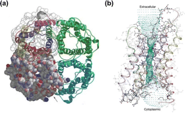 | ||
| Fig. 4 (a) AQP-1 tetramer viewed normal to the membrane; two of the monomers also contain a space-filling model to show the pore entrance. (b) The ribbon-like backbone of AQP-1. Adapted from ref. 32 with permission. Copyright 2001, Springer Nature. | ||
2.2 Physical confinement
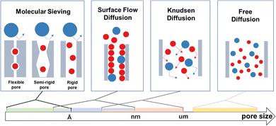
Physical confinement refers to the static steric hindrance toward molecular mass transport within a nanochannel, when the interaction between the guest molecule and the wall of the channel is weak.The degree of confinement can be defined by the ratio of channel equivalent diameter and the molecular free path. When the degree of confinement is greater than 1, molecules commonly diffuse freely within the channels and gas flux is controlled by pressure without a confinement effect. When the degree of confinement is less than 1, gas molecules collide with the wall of the nanochannel, rather than among themselves. Based on diffusion properties and channel size, physical confinement can be further divided into Knudsen diffusion, surface flow diffusion and molecular sieving (Fig. 5).
When gas molecules make random elastic collisions and have no obvious interactions with the pore surface, gas transport is adequately described as Knudsen diffusion.35,36 The permeance is calculated based on eqn (1)37 as follows:
 | (1) |
According to this equation, when different gas molecules pass through the same channel via Knudsen diffusion under the same conditions, then the gas flux is inversely proportional to the square root of the molecular mass, which is termed as Knudsen selectivity. As the channel size is reduced, the mobility of gas molecules is greatly restricted, and molecular mass transport is dominated by the pore wall geometry. Geim and Radha constructed 2D channels with different roughness.38 Channels made from graphene or boron nitride possess an atomically flat wall, which leads to frictionless gas flow. In contrast, relatively rough channels made from molybdenum disulfide walls exhibit much slower permeation.
Some organic microporous membranes have a certain adsorptive effect on some gas molecules, such as CO2 molecules. In this context, gas transport is predominantly by surface flow diffusion and is obviously affected by the pore wall surface potential field. Due to the adsorption interactions, adsorbed molecules are enriched on the pore surface, at a density significantly greater than in the bulk gas phase, which influences the collisions and mean free path. The free path is molecularly defined by Verweij et al.39 by eqn (2):
| λsurf = (ρsurfσ)−1 | (2) |
Once adsorbed, the gas molecules require additional activation energy (ΔE) to make diffusive jumps to other adsorption sites (Fig. 6). ΔE is dominated by both surface potential field and roughness. The surface flow diffusion mechanism is generally used to describe the regional transport behavior close to the pore wall, while the overall transport may need to be described by comprehensive analysis of Knudsen diffusion and molecular sieving processes.
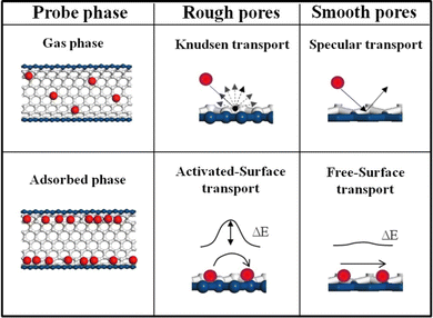 | ||
| Fig. 6 Transport mechanisms and an illustration of the fractional contributions of the gas phase and adsorbed phase. Adapted from ref. 35 with permission. Copyright 2015, Elsevier. | ||
When the channel size is smaller than the molecular size of a particular gas, the gas is prevented from transiting. To achieve molecular sieving, the channel size is designed to be in between the size of the gas molecules to be separated. Koros and Zhang40 have analyzed in-depth the contributions of entropy and enthalpy to diffusion selectivity. The mechanism is universal and also applicable to organic microporous membranes. For rigid-structured COF and MOF membranes, the entropic selectivity dominates the molecular sieving effect. Passing through the micropore windows, larger molecules experience suppressed rotational and possibly even vibrational degrees of freedom in the transition state. Hindrance of motion in the diffusion transition state of the larger molecule enables higher selectivity. For more flexible-structured polymer membranes, segmental motions lead to a distribution of penetrant-scale gaps and thus weak entropic selectivity. The difference in activation energies (or enthalpies) is responsible for creating size-selective transient gaps, thereby providing diffusion selectivity. For the semi-rigid-structured PIM membranes and TR membranes, the molecular sieving originates from both entropic and enthalpic selectivity. The entropic difference is provided by the bottlenecks between the individual free volume elements but is also influenced by chain motion.41 In this context, crystalline framework-based materials should have advantages in entropic selectivity for the efficient separation of similar-sized molecules. However, framework flexibility or the breathing effect has been observed, which thwarts molecular sieving. Due to the rotation of coordination bonds or the unique interlocking structure, some MOF membranes exhibit stimuli-responsive dynamicity with a larger effective pore size than the crystallographic dimensions. For instance,42 the well-known ZIF-7 membranes possess a narrow-pore phase (ZIF-7-II) and a large-pore phase (ZIF-7-I), triggered by CO2 uptake and release. ZIF-7-I permits molecules of up to ∼5.2 Å diameter to enter the main cavities, far beyond the crystallographic pore size of 3.0 Å. Therefore, the so-called motion-enabled zones within these types of membranes sometimes exhibit a higher priority to the overall selectivity than the available pore space.
2.3 Chemical confinement
Chemical confinement refers to the mass transport behavior in which the specific active sites distributed within the confined channels can form chemical interactions or strong interactions with molecules. Not synonymous with facilitated transport, chemical confinement also demonstrates the aspects of space topology, neighbor carrier distribution and unique gas–channel wall coupling. Since the pore channels of organic microporous membranes are only a few molecules wide, the chemical groups on the wall can significantly affect the mass transfer behavior and gating effect. Based on the physicochemical properties of CO2, constructing the aqueous layer or ion layer within the organic microporous membrane has a significant reinforcement effect on the mass transport of CO2. Based on the primary confinement, when strongly coupled, CO2 may be captured by the wall of the channel, generating a new layer and the so-called secondary confinement effect (Fig. 7).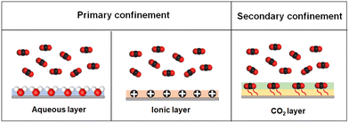 | ||
| Fig. 7 Chemical confinement mechanisms and an illustration of the aqueous layer, ionic layer and CO2 layer on the channel wall. The secondary confinement is constructed by two layers. | ||
Inspired by biological membranes, CO2 is usually transferred in the form of carbonic acid and bicarbonate, wherein water molecules act as the essential medium and reactant participating in the transport. Thus, these related membranes with chemical confinement are frequently modified with specific carriers, including amino groups, acidic groups and metal ions, which interact with water molecules and promote hydration and CO2 transport. Guiver and Jiang43 introduced borate ions interspersed between GO nanosheets as both a cross-linker and a facilitated transport carrier of CO2. The carriers are evenly distributed on the channel wall, being derived from the chemical interaction between B4O72− and hydroxy groups in GO. The channel size was tuned to 0.35 nm, enabling size sieving between CO2 and CH4. Under humidified conditions, the boric acid–water complex rapidly deprotonates to B(OH)4, which further catalyzes the conversion of CO2 to HCO3− by a similar mechanism to that of carbonic anhydrase. The membranes exhibited outstanding performance, with a permeance of up to 650 GPU and a CO2/CH4 selectivity of 75. Ammonia also shows excellent performance in these water–gas-coupled transport mechanisms. The reaction sequences are given in eqn (3)–(6):
| CO2 + RR′NH ⇌ RR′NH+COO− | (3) |
| RR′NH+COO− + RR′NH ⇌ RR′NCOO− + RR′NH2+ | (4) |
| RR′NH+COO− + H2O ⇌ RR′NCOO− + H3O+ | (5) |
| RR′NCOO− + H2O ⇌ RR′NH + HCO3− | (6) |
Metal ion-based facilitated transport membranes have also shown good prospects, and various metal ions (e.g., Ca2+, Ag+, Cd2+, Co2+, K+, and Zn2+) have been studied as facilitated transport carriers. CO2 molecules provide π electrons to the empty s orbital of the metal ion to form σ bonds. The empty π* anti-bonding orbitals of CO2 molecules accept d electrons from the metal ions to form π bonds. The unstable metal–CO2 transitory complex is apt to revert to releasing CO2.45 Hence, the reversible interactions between metal ions and CO2 facilitate the fast transport of CO2.
MOF membranes provide a good platform for constructing mass transfer channels with continuous metal sites. Liu46 prepared a defect-engineered zirconium–MOF membrane enabling superior CO2/N2 selectivity with a zirconium-oxo cluster source. The missing-linker in the UiO-66 framework led to increased porosity and coordinative unsaturated open metal sites, facilitating the transport of CO2. Besides that, Webley and Qiao designed a membrane with a polymer-on-MOF architecture,47 whereby the MOF layer was covered by a continuous 30 nm-thick crosslinked polymeric layer. The ultrathin polymer layer is the selective layer, while the MOF layer provides high mass transport with continuous metal ions as transport carriers. The permeance is above 3000 GPU and the CO2/N2 selectivity is 34, achieving the best CO2/N2 separation performance at that time.
Secondary confinement, as a novel separation mechanism, refers to the species to be separated coupled with the surface of the inherent channel, forming a new solid-state-like layer. The secondary confinement layer shows an obvious steric hindrance effect and endows the membrane with new pore size. The secondary confinement is a paradigm of fluid–solid coupling and provides a feasible solution to the problem that the channel size of some organic microporous membranes is excessively large for many molecular separation processes.
Jiang48 designed an ionic liquid-confined COF membrane for efficient ethylene/ethane separation. The pore size of the native COF membrane was 1.44 nm, but it was tuned to 0.87 nm after loading it with a silver ion-containing ionic liquid. The tuned pore was slightly more than double the diameter of ethylene molecules and the coupled ethylene impeded the permeation of ethane. With regard to CO2 separation, the channel wall could also be modified with an adsorbed CO2 layer to enhance the molecular sieving effect.49,50 Wang and Guiver designed a polymer-constructed MOF hybrid material and incorporated it into PVAm as a selective layer to provide ultrathin unobstructed gas transport channels.49 Due to the strong interaction between amino groups and CO2, the CO2 was adsorbed on the channel wall, which decreased the effective aperture from 1.5 nm to 0.33 nm. The membranes achieved a high CO2 permeance of 823 GPU and a CO2/N2 selectivity of 242 (Fig. 8).
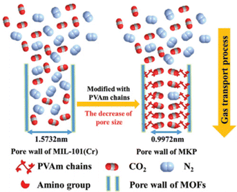 | ||
| Fig. 8 Schematic diagram of the CO2 gas transport process based on secondary confinement. Adapted from ref. 49 with permission. Copyright 2020, Wiley. | ||
3. Design principles of organic microporous membranes
Design principles are defined here as the pathway to transform organic microporous materials to high performance membranes. This part encompasses many aspects, which include manipulation of building blocks, identification of the membrane structures, modification of pore structures and microporosity, assembly of building blocks and host–guest interrelationships. In this section, we discuss ideal high-performance membrane structures and propose three general approaches: nano-assembly engineering, reticular engineering and microenvironment engineering. Nano-assembly engineering focuses on the assembly of 2D and polymeric membranes with ultrathin selective layers. Reticular engineering concentrates on crafting continuous defect-free framework (i.e. COF and MOF) membranes. Microenvironment engineering is aimed at optimizing the interaction of gas molecules and membranes, thus improving the rate of mass transfer. We aim to provide in-depth perspectives and inspiration for researchers based on these membrane engineering approaches.3.1 Nano-assembly engineering
Membrane selective layer thickness is directly related to the mass transfer distance of gas molecules, which is further inversely proportional to permeance/permeability.51 Decreased membrane thickness can effectively shorten the length of selective channels, directly reducing the time required for gas molecules to transit the membrane. Nano-assembly to shorten the mass transfer path is a conventional strategy to obtain high permeance membranes without compromising selectivity. Currently, the most common method to reduce the mass transfer path is by depositing or forming a selective skin layer onto a porous support layer (i.e., thin film composite (TFC) membranes). Polymeric materials and 2D nanosheets are solvent processable, allowing defect-free thickness-adjustable selective layers to be readily fabricated. This is exemplified by PIMs (featuring contorted, rigid ladder-like backbones) and graphene-based nanosheets having high aspect ratios. Several common nano-assembly approaches are introduced below, including filtration assembly, coating assembly, layer by layer (LbL) assembly and interfacial polymerization (Fig. 9).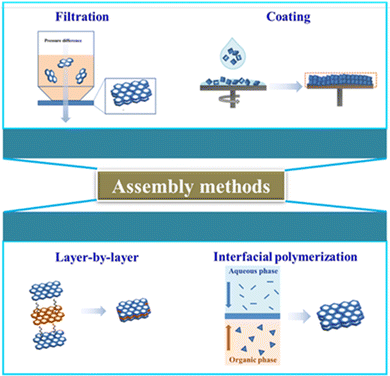 | ||
| Fig. 9 Representative assembly methods of high-permeability gas separation membranes. Reproduced with permission from ref. 29. Copyright 2021, Royal Society of Chemistry. | ||
LbL self-assembly refers to a process of alternating deposition of nanolayers or nanosheets onto the surface of porous substrates. The thickness of the selective layer can be finely adjusted by varying the deposition cycles. Gascon et al.56 used an LbL self-assembly process to successively deposit horizontal 1 nm thick PIM monolayers onto an ultrapermeable poly(trimethylsilyl)propyne (PTMSP) substrate, with the membrane thickness depending on the number of deposition cycles. The ultrathin (∼30 nm) PIM membranes exhibited seven times higher CO2 permeance and similar CO2/N2 selectivity in comparison with freestanding PIM membranes, while using only 0.04% polymer compared with dense PIM membranes.
Interfacial polymerization is frequently used industrially to produce ultrathin selective layers by segregating the monomers in immiscible solvent phases to confine the reaction-assembly process at the interface. Using interfacial polymerization, Jimenez-Solomon et al.57 fabricated freestanding 20 nm thick nanofilms at the oil–water interphase within minutes. The formed nanofilms with adjustable thickness were transferred to an anodized aluminum oxide (AAO) support. Different phenols with contorted or non-contorted orientations were introduced to obtain a series of nanofilms, manifesting the universality and controllability of interfacial polymerization in microstructure manipulation.
An extreme example of an ultrathin membrane is when the selective layer is of the thickness of a single atom, which can achieve ultimate separation.58 As an archetypal example, nanoporous single-layer graphene (NSLG) can yield orders of magnitude higher permeance than conventional membranes. Nevertheless, one key bottleneck restricting the scale-up production of NSLG membranes is the avoidance of crack formation, tears and wrinkles during the transfer of large-area NSLG onto porous supports, which will degenerate gas separation performance.59 The most common approach is mechanical reinforcement to support NSLG. Initially, the wet method by coating assembly using a sacrificial polymer film (e.g. poly(methyl methacrylate) (PMMA)) was investigated predominantly, owing to its use as a reinforcement layer in various substrates.60,61 However, significant tearing and folding on the graphene surface evolve if porous substrates are used, which is ascribed to the strong capillary force generated during the polymer dissolution and solvent evaporation stage. Most recently, nanoporous carbon62 and carbon nanotube mesh63 were explored as new-generation reinforcement layers to prepare large-area NSLG membranes. For instance, Huang et al.62 reinforced the NSLG membrane with a freely removable nanoporous carbon layer, achieving crack-free transfer of millimeter-sized NSLG onto a porous substrate. Based on this, an ultrahigh flux H2-sieving selective membrane was obtained.
3.2 Reticular engineering
Reticular chemistry refers to a bottom-up synthetic approach in which judiciously designed rigid molecular building blocks are purposely assembled into crystalline extended framework structures linked by strong directional bonds (e.g., covalent or coordination).29,64 Reticular engineering originates from reticular chemistry but it focuses on the engineering strategies for intended applications (CO2 separation membranes).65 Owing to the inherent size and rigidity of building blocks, their connection or assembly forms a framework structure, producing permanent pores within the structure. Moreover, the connectivity between adjacent pores, in addition to the accessibility of the internal channel to guest molecules, further provides exceptional advantages for their use as gas separation membranes. These characteristics are distinctive compared with conventional polymer materials. Most synthesized reticular materials (e.g., COFs or MOFs) are in the form of dispersed powders, and transforming them into continuous defect-free membranes is highly challenging.66 The objective of reticular engineering in the context of membranes is the predesign of building block materials that assemble into abundant micropores (i.e., mass transfer nanochannels) that match the intended membrane separation process, realizing high CO2 permeability of COF/MOF membranes.As an archetypal subset of reticular material, MOFs are constructed from metal-containing nodes and organic linkers via coordination bonds. They have long been preeminent platforms for gas separation, especially for CO2.67 Si et al. synthesized CAU-1 powders from 2-amino terephthalic acid as the organic linkers and Al3+ as the metal framework nodes.68 CAU-1 is comprised of a pseudo-body-centered-cubic arrangement of wheel-shaped building blocks. The three-dimensional MOF contains many distorted octahedral and tetrahedral cages, which are easily accessible through its small open triangular windows. The Brunauer–Emmett–Teller (BET) specific surface area and pore volume can reach 1268 m2 g−1 and 1.32 cm3 g−1, respectively. Based on this work, Jian et al. employed a simple in situ solvothermal method to prepare thin tubular CAU-1 membranes.69 The selection of various experimental parameters, such as the solvent ratio, reactant concentration and substrate properties, is of prime importance to engineer a dense and continuous CAU-1 membrane with effective separation performance. Careful adjustment of ethanol concentration and the selection of Al2O3 support resulted in a well-intergrown pure CAU-1 membrane exhibiting a high CO2 permeance of 2300 GPU with a selectivity of 14.8 for CO2/N2 at ambient temperature. The performance exceeded that of many reported polymer membranes, highlighting the significance that MOF membranes can be prepared with optimized network topologies, permanent accessible porosity and suitable structural functionalities by adjusting the structural organic linkers and metal nodes, spatial arrangement and reaction parameters.
COFs are constructed from purely organic building units through strong covalent bonds. One distinct characteristic of COFs is that the polygon skeleton and pore size can be precisely tailored by using topology diagrams depending on the geometry matching of various building blocks.70 High specific area, controllable pore size along with all the organic structure, are the characteristics that enable COFs to form into nanocrystals that can be processed into robust membranes for efficient gas separation. The first COF was developed through reversible formation of the B–O bond,71 which readily cleaves upon exposure to moisture. In contrast, C–N linked COFs are chemically and thermally more stable. Narrower channels are accessible by using shorter lengths of building units, such as azine units. For example, hydrazine hydrate condenses reversibly with 1,3,5-triformylbenzene to form azine-linked ACOF-1,72 which has a hexagonal structure with P6/m symmetry for eclipsed AA stacking. The BET surface area of ACOF-1 is more than 1000 m2 g−1, while the pore size is centered at about 0.94 nm and is smaller than that of most of other reported COFs. Based on the work of Li et al., Caro's group fabricated continuous and dense ACOF-1 membranes on the α-Al2O3 support via a solvothermal method.73 The pre-coated PEI on the support effectively inhibits the homogeneous nucleation and intensifies the heterogeneous nucleation. Thus, a continuous ACOF-1 membrane with well-intergrown grains can be obtained. The resulting ACOF-1 membrane exhibited a high selectivity of close to 100 for CO2/CH4 with a favorable 300 barrer gas permeability, which was ascribed to the narrowed membrane pores formed during the intergrowth stacking of crystalline grains and the blocking of the CH4 diffusion path due to the confinement effect in the narrow pores (Fig. 10).
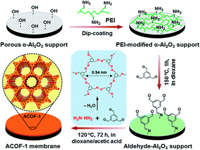 | ||
| Fig. 10 Schematic illustration of fabricating ACOF-1 membranes guided by reticular engineering. Reproduced with permission from ref. 73. Copyright 2018, Royal Society of Chemistry. | ||
Reticular engineering not only greatly advances the status of framework-based materials but also fills the gap between material design and framework membrane construction. Even though considerable progress has been made, reticular engineering of framework gas separation membranes still faces a number of challenges, such as large-scale membrane production and the inherently large-sized pores of COFs.
3.3 Microenvironment engineering
Nanochannels are one of the structural features of certain types of gas separation membranes. The so-called nanochannel microenvironments exert a profound influence on the overall separation performance of membranes. Different types of microenvironments have an effect on different separation processes. The key points of microenvironments mainly include nanochannels, rigidity/flexibility and chemically active sites. The aim of microenvironment engineering is to enhance the rate of mass transfer by reducing transport resistance or exploit specific interactions with target molecules, to obtain high permeability and/or achieve molecular sieving. In the following section, different microenvironment engineering strategies are introduced.Nanochannel flexibility/rigidity refers to the capability of reversible expansion and contraction, which is a parameter to achieve improvements in separation performance.74 In essence, nanochannel flexibility depends mostly on the intrinsic flexibility of organic linkers. Bereciartua et al. reported a narrow-nanochannel silica zeolite, ITQ-55, whose flexible framework structure coupled with heart-shaped cages enables the precise separation of target ethylene molecules from ethane molecules.75 Owing to the framework flexibility, the target molecules become size fitting molecules to accelerate diffusion through bracing the narrow nanochannels open. The diffusion of ethane molecules having a slightly larger size is restricted by nearly two orders of magnitude, thus achieving an unprecedented selectivity of approximately 100 for this challenging separation (Fig. 11a). Framework flexibility greatly influences solubility and melt-processability, reflecting the membrane-forming properties to some extent, while framework rigidity reflects intermolecular bond strength, and is viewed as an indicator of high free volume and long-range order. Thus, ‘synergistic rigidity and flexibility’ can be beneficial simultaneously in achieving the target gas separation performance. Framework flexibility can be classified into four primary types: breathing, swelling, organic linker rotation and subnet sliding. The inherent lattice flexibility of ZIF-8 resulting from ligand rotation has been extensively studied. The rotation of organic linker 2-methylimidazole leads to gate opening, which allows larger molecules to diffuse through the nanochannels and lessen its intrinsic sieving capacity. To hinder linker movement, Zhou et al. synthesized ZIF-8_Cm (a newly discovered monoclinic polymorph of ZIF-8)-dominated membranes through a fast current-driven synthesis (FCDS).76 The ZIF-8_Cm polymorph, accounting for up to 70% of the synthesized ZIF-8 crystals, possesses a stiffer framework structure than the common ZIF-8 phase, to better suppress linker mobility. Because of this, the permeation of larger molecules is greatly decreased and sharper molecular sieving can be achieved (Fig. 11b).
 | ||
| Fig. 11 (a) Description of the silica zeolitic structure of ITQ-55. (b) Fast current-driven synthesis of the ZIF-8 membrane. Reproduced with permission from ref. 75 and 76. Copyright 2017, American Association for the Advancement of Science. Copyright 2018, American Association for the Advancement of Science. | ||
Other than the above-mentioned nanochannel character, functional sites within nanochannels also dominate the gas transport processes in membranes. The functional sites refer to active groups or carriers, which can controllably interact with target molecules to facilitate gas molecule dissolution and transport within the nanochannels. Significantly, functional sites can impose not only interaction forces of attraction, but also repulsion forces with molecules.77 The separation performance can be greatly influenced by the position of functional sites within mass transport nanochannels, which can be tailored either by predesign or by post-modification. Guo et al. integrated amphoteric aspartic acid (ASP) to the positively charged framework of the DhaTGCl membrane by ion exchange.78 Owing to the long-range ordered nanochannels, the amino and carboxyl groups of anchored ASP align continuously and with high-density along the nanochannels. These groups specifically interact with polar CO2 molecules, facilitating the selective transport of target CO2 molecules through the membrane. In comparison with the DhaTGCl membrane, the modified DhaTGASP membrane had a two-fold increase in permeability and selectivity. Different from organic functional groups, transition metal cations are effective for facilitated CO2 transport only in the dry state. Peng et al. constructed CO2 facilitated transport nanochannels by incorporating different divalent metal ions into poly(N-vinylimidazole) (PVI)@carbon nanotube (CNT) membranes.79 Compared with main-group metal ions (Ca2+ and Mg2+), transition metal ions (Cu2+ and Fe2+) had stronger π-complexation with CO2 molecules, and are thus more efficient as CO2 carriers to facilitate transport. The electronegativity of the metal element directly determines the π-complex strength, which influences CO2 facilitated transport behavior and separation performance.
4. High-performance organic microporous membranes
In this section, we discuss four representative organic microporous membranes, encompassing PIM, GO, MOF and COF membranes. We systematically assess the material structure, unique preparation methods, and separation performance, and summarize the opportunities for their future development.4.1 PIM and TR polymer-based membranes
Gas diffusivity and diffusion selectivity in polymer membranes are mainly determined by free volume and chain rigidity, respectively. PIM and thermally rearranged polymers (TR polymers), lacking single bonds and conformational flexibility that inhibit backbone rotation and mobility causing inefficient packing, trap micropores and free volume. Benefiting from this, PIM and TR polymers are membrane materials of high interest for CO2 separation.A step change in the design of polymeric materials for gas separation occurred in 2004 with the discovery of a new class of solvent-soluble materials referred to as PIMs, by the inventors Budd and McKeown.15,80 PIMs lack single bonds in the polymer chain and thus have rigid backbones with very limited conformational flexibility. The polymer chain also contains sites of contortion, resulting in kinked and irregular rigid backbones that prevent efficient chain packing, giving high fractional free volumes with surface areas typically above 700 m2 g−1. PIM membranes usually exhibit ultrahigh permeability, far exceeding that of conventional polymers for most gases. Membrane studies on various structural PIMs have accelerated over the nearly twenty years of development, which include (i) incorporating new units into backbones to enhance chain rigidity and (ii) post-modification of PIM membranes.
In spite of the presence of ladder-like backbones, it is notable that there is a certain degree of conformational flexibility directly related to spirocentres of the 1,1′-spirobisindane units. Thus, introducing more rigid moieties to yield less flexible macromolecules is a straightforward approach to enhance gas permeability and selectivity. Soluble rigid units, such as spirobifluorene (SBF),81 Tröger's base (TB)82 and hexaphenylbenzene (HPB),83 have been utilized as structural units in PIMs, which have been comprehensively introduced in our previous review. Recently, SBF building blocks with substituents such as methyl, t-butyl and fused benzo groups were employed to synthesize various PIM-SBF membranes.84 In particular, PIM-SBF-2 derived from four-methyl substituted SBF showed the highest CO2 permeability of 22![[thin space (1/6-em)]](https://www.rsc.org/images/entities/char_2009.gif) 300 barrer among various PIM-SBFs, which is ascribed to the enhanced intrinsic microporosity arising from increased inter-chain distance. An interlocked SBI, whose spirocenter was encumbered by an eight-membered dihydrooxocine ring, was incorporated into PIM (PIM-C1), to suppress planar flexing around the SBI spirocyclic hinge point, resulting in more sparsely packed polymer chains and a longer inter-chain distance in comparison with PIM-1.85 Thus PIM-C1 exhibited a higher permeability of 18
300 barrer among various PIM-SBFs, which is ascribed to the enhanced intrinsic microporosity arising from increased inter-chain distance. An interlocked SBI, whose spirocenter was encumbered by an eight-membered dihydrooxocine ring, was incorporated into PIM (PIM-C1), to suppress planar flexing around the SBI spirocyclic hinge point, resulting in more sparsely packed polymer chains and a longer inter-chain distance in comparison with PIM-1.85 Thus PIM-C1 exhibited a higher permeability of 18![[thin space (1/6-em)]](https://www.rsc.org/images/entities/char_2009.gif) 900 barrer with a CO2/N2 selectivity of 19 and a CO2/CH4 selectivity of 14.
900 barrer with a CO2/N2 selectivity of 19 and a CO2/CH4 selectivity of 14.
The incorporation of rigid non-planar bridged bicyclic components, exemplified by triptycene (Trip) and benzotriptycene (BTrip), into PIM backbones has resulted in high FFV and high permeability, originating from disrupted chain packing.86 By fusing two triptycene units to the spirobisindane unit one can synthesize PIM-SBI-Trip with a highly rigid polymer chain, brought about by the much reduced flexibility of the spirocenter site of contortion and the inherent rigidity and bulky structure of the bridged triptycene. The large triptycene substituents and the rigid backbone hinder efficient chain packing and increase the inter-chain spacing, resulting in high porosity and FFV. Thus, PIM-SBI-Trip demonstrated a CO2 ultrapermeability of 35![[thin space (1/6-em)]](https://www.rsc.org/images/entities/char_2009.gif) 600 barrer, and is the first ultrapermeable PIM with 3D contorted polymer chains. The group of McKeown further incorporated various substituted BTrip units to replace spirobisindane, to fabricate 2D PIM membranes (Fig. 12).12 Each triptycene within the backbone is coplanar to neighboring units, allowing construction of 2D ribbon-like chains. The 2D ribbon-configured PIM exhibits much less efficient polymer chain packing than PIMs with 3D contorted chain structures, leading to more interconnected micropores and FFV, favoring fast gas diffusion. Incorporating solubilizing and sterically-crowded substituents such as tetramethyltetrahydronaphthalene (TMN), hexamethylindane (HMI) and trifluoromethyl, which extend out from the ribbon-shaped backbones, further disrupt the chain packing by creating greater 2D aspect ratios. Thus, BTrip-based PIM membranes exhibit very high selectivity for CO2/light gas and high permeability, which compete with ultrapermeable PTMSP for the first time. In particular, PIM-TMN-Trip has an ultrahigh CO2 permeability of 52
600 barrer, and is the first ultrapermeable PIM with 3D contorted polymer chains. The group of McKeown further incorporated various substituted BTrip units to replace spirobisindane, to fabricate 2D PIM membranes (Fig. 12).12 Each triptycene within the backbone is coplanar to neighboring units, allowing construction of 2D ribbon-like chains. The 2D ribbon-configured PIM exhibits much less efficient polymer chain packing than PIMs with 3D contorted chain structures, leading to more interconnected micropores and FFV, favoring fast gas diffusion. Incorporating solubilizing and sterically-crowded substituents such as tetramethyltetrahydronaphthalene (TMN), hexamethylindane (HMI) and trifluoromethyl, which extend out from the ribbon-shaped backbones, further disrupt the chain packing by creating greater 2D aspect ratios. Thus, BTrip-based PIM membranes exhibit very high selectivity for CO2/light gas and high permeability, which compete with ultrapermeable PTMSP for the first time. In particular, PIM-TMN-Trip has an ultrahigh CO2 permeability of 52![[thin space (1/6-em)]](https://www.rsc.org/images/entities/char_2009.gif) 800 barrer, surpassing the permeability of nearly all state-of-the art polymeric membranes. The exceptional gas separation performance of BTrip-based PIM necessitates the redefinition of the CO2/N2 and CO2/CH4 upper bounds.
800 barrer, surpassing the permeability of nearly all state-of-the art polymeric membranes. The exceptional gas separation performance of BTrip-based PIM necessitates the redefinition of the CO2/N2 and CO2/CH4 upper bounds.
 | ||
| Fig. 12 Structure and synthesis of benzotriptycene PIMs. Reproduced with permission from ref. 12. Copyright 2019, Royal Society of Chemistry. | ||
Replacing backbone structures with less conformational freedom by adding or replacing more rigid moieties to improve permeability has been explored. The group of Smith adopted an innovative unexploited strategy of designing a bottlebrush polymer by attaching inflexible, microporosity-forming side chains to a flexible backbone.87 Ring-opening metathesis polymerization (ROMP) was applied to synthesize flexible poly(norbornene) main chains with inflexible side chains. The rigid pendant species were made by an iterative Diels–Alder reaction, producing oligomers with different chain lengths of 2–9 repeat units, leading to an ultrahigh CO2 permeability of 21![[thin space (1/6-em)]](https://www.rsc.org/images/entities/char_2009.gif) 266 barrer. The unique structural characteristics also bring out outstanding physical aging and plasticization resistance. The lower physical aging rate of ROMP polymers coupled with much higher CO2 permeability compared with conventional PIM-1 establishes an alternative polymer platform to address the current challenges of CO2 separation. Both of the ROMP polymers, which exhibit the highest plasticization resistance among PIM-based polymers (plasticization pressure >51 bar), represent a type of platform material to tackle plasticization limitations.
266 barrer. The unique structural characteristics also bring out outstanding physical aging and plasticization resistance. The lower physical aging rate of ROMP polymers coupled with much higher CO2 permeability compared with conventional PIM-1 establishes an alternative polymer platform to address the current challenges of CO2 separation. Both of the ROMP polymers, which exhibit the highest plasticization resistance among PIM-based polymers (plasticization pressure >51 bar), represent a type of platform material to tackle plasticization limitations.
Post-modification by thermal, chemical or physical treatment is one common approach to improve the gas selectivity of PIMs. An optimized intermediate temperature (450 °C) between cross-linking and carbonization was selected to tune the micropores of PIM-1.88 With the synergistic effects of decomposition and thermal crosslinking, the pyrolyzed polymer fragments partially occupied the free volume, resulting in significantly better molecular-sieving for the H2/N2, H2/CH4 and CO2/CH4 gas pairs. Carboxylate,89 amidoxime,90 tetrazole,91 amine92 and thioamide93 functionalized PIMs have been synthesized by chemical post-modification, which typically led to the reduction of available micropores and enhancement of selectivity. Yavuz94 and Pinnau90 reported amidoxime-functionalized PIMs (AO-PIM-1). The amidoxime functionality rigidifies the polymeric matrix and thus narrows the porosity towards finer ultramicroporosity, reducing the diffusion of gases with larger kinetic diameters. Recently, Li and co-workers adjusted the microporosity of PIM-1 by atomic layer deposition (ALD) of Al2O3, wherein the amount and placement of Al2O3 within the micropores could be systematically tailored.95 The resulting PIM-1-Al2O3 achieved precise molecular sieving, exhibiting high separation performance for H2/N2, H2/CH4 and CO2/CH4.
Even though PIM membranes have reasonable mechanical properties and are thermally stable, several challenges need to be tackled. Expensive monomers and complex synthetic procedures encumber the wider application of PIM membranes. Physical aging in some PIM membrane structures may be higher than other membrane materials from the industrial perspective in the conventional thinking of most people. Many PIM membranes encounter a phenomenon whereby permeability decreases and selectivity increases on aging,96 which may influence industrial adoption due to unsteady initial operating performance. Polymer backbone design and post-modification are two possible approaches to address this. In addition, with the growth of microporous materials exemplified by PAFs and MOFs, blending microporous fillers with PIMs is acknowledged as a promising strategy to suppress physical aging. In fact, even with physical aging, some PIMs remain well above the upper bound, tending to increase selectivity, while undergoing some decrease in permeability.97 The PIM-Btrip membrane exhibited an 82% increase in CO2/CH4 selectivity with a relatively low 40% decrease in CO2 permeability after 4 month aging.12 The overall separation performance of the aged membrane is even better than that of the as-prepared membrane. Even if the aging time is prolonged to two years, the PIM-BTrip membrane still exhibits a CO2/CH4 selectivity of 33.8 and a CO2 permeability of 3770 barrer, indicating that aging does not necessarily result in the loss of separation performance. Recently, Smith and Xia prepared a class of hydrocarbon ladder polymers with rigid backbones via catalytic arene-norbornene annulation (CANAL) polymerization and the resulting membranes exhibited both high selectivity and permeability due to the unique 3D-contorted configuration. Surprisingly, aging of these kinds of membranes significantly improved the selectivity, unlike a number of conventional PIM membranes. The aged CANAL membrane showed outstanding performance with a CO2/CH4 selectivity of 46 and a CO2 permeability of 600 barrer. The abnormal aging behavior is related to free volume with a certain sieving effect, in which the transport of larger gases (above 3.5 Å) is restricted and the transport of smaller gases is weakly affected. This work suggests new opportunities for the molecular design of PIM membranes.98
Besides the chemical composition and microstructure of PIMs, the membrane configuration is another significant influencing factor, which determines the application aspect of PIM membranes. Currently, the majority of PIM work is on self-supported dense film membranes, with relatively less research related to hollow fiber99,100 or TFC configuration.101,102 Jue et al. prepared asymmetric integrally skinned PIM-1 hollow fiber membranes (HFMs) through a modified dual-bath spinning method.103 Surprisingly, the two-month aged HFMs having a selective layer of 3–6 μm exhibited a promising CO2 permeance of 360 GPU and a CO2/CH4 selectivity of 23. Budd's group prepared PIM TFC membranes of various thickness (1.6–8.0 μm) of the selective layer by dip-coating the casting solution onto the solvent-resistant PAN support.104 In comparison with the much thicker self-supported membrane (60–90 μm), the TFC membrane showed much improved CO2 permeance at similar filler-loading. Moreover, filler loading in TFC membranes could reach nearly 60 wt%, much higher than that in self-supported membranes (17 wt%). Interestingly, even though TFC and self-supported membranes exhibit similar trends of CO2 permeability and CO2/N2 selectivity, the duration of physical aging of each membrane is obviously different, which is 90 days for the TFC membrane and beyond 200 days for the self-standing membrane. In terms of routine industrial applications, membranes are fabricated in TFC and hollow fiber configuration, and a thinner selective layer leads to faster aging.
Thermally rearranged polymers (TR polymers) are obtained by thermal treatment of polyimide (PI) and polyamide (PA) precursors containing ortho-hydroxy groups. Recent progress in TR polymers follows a similar approach as with PIM membranes. In particular, research on introducing shape-persistent and micropore-forming units has been extensively investigated to induce more accessible free volume to enhance gas permeability.105 Recently, TR polymers with bulky adamantyl (AD) units were synthesized by Lee and Lozano.106 All AD-incorporated TR polymers exhibit an increase in FFV and gas permeability, which is due to chain packing inhibition. The AD (0.5) membrane after 450 °C thermal treatment achieved a >15-fold increase in CO2 permeability without a significant decrease in selectivity, and surpassed the 2008 Robeson upper bound. In other work, the introduction of bulky triptycene units into PI precursors led to a 56× improvement in CO2 permeability and a 28% increase in CO2/CH4 selectivity compared with the original precursors, which is due to the high backbone rigidity and the free volume interconnectivity after TR conversion.107 Crosslinking can be applied as an auxiliary approach to adjust the free volume in TR membranes. The bismaleimide (BMI) membrane is made by polycondensation and in situ crosslinking of maleimide-substituted monomer building blocks.108 After the TR process, the resulting BMI-based TR (TR-BMI) membrane exhibits a tremendous increase of BET surface area from 10.8 m2 g−1 (BMI) to 1130 m2 g−1 (TR-BMI). With the synergistic effect of crosslinking and TR conversion, a high CO2 permeability (5440 barrer) and favorable selectivity (CO2/CH4: 37, CO2/N2: 23) are obtained. TR membranes can simultaneously achieve satisfactory permeability, high selectivity, superior stability and good mechanical strength, which makes them competitive in the area of carbon capture.
4.2 Single-layer graphene and graphene oxide membranes
The isolation of graphene by Geim and Novoselov as a vital milestone has attracted intense attention in the field of 2D-materials for not only scientific research interest, but also industrial application expectations.109 Beneficial features such as ultrathin selective layers, controllable interlayer spacing, excellent membrane formation capabilities and superior mechanical stability make graphene and its derivatives a promising building block for the development of a new generation of high-permeability gas separation membranes.110,111 Graphene is a single layer of graphite containing numerous repeating hexagonal networks which is composed of sp2 hybridized carbon atoms.112 Graphene by itself is impermeable to liquids, vapors and even small gas molecules like helium, due to the blocked space caused by the delocalized cloud of p-orbitals.113 Therefore, molecular transport nanochannels must be constructed for use in gas separation.One feasible approach is to create in-plane nanochannels by perforating nanopores in the single-layer graphene (SLG), which is the most direct method to control gas diffusion and obtain size-sieving properties. Chemical vapor deposition (CVD) is a well-established method to fabricate SLG membranes with scalable size supported on substrates.114 The common perforation techniques can be classified into physical methods (focused ion beam (FIB) irradiation, focused electron beam (FEB) irradiation and ion bombardment) and chemical methods (chemical oxidative etching, plasma etching and ultraviolet (UV) light etching). While much progress has been made, combining two perforation technologies can be more effective to obtain high perforation density and high size resolution nanochannels within SLG membranes than by just a single method. Recently, Huang et al. developed a millisecond lattice gasification technique to introduce a high density of nanopores with sub-angstrom precision in SLG membranes.115 The gasification perforation process is scalable, and uniform centimeter-scale membranes can be obtained. Thus, the nanoporous single-layer graphene (NSLG) membranes have ultrahigh CO2 permeability (>10![[thin space (1/6-em)]](https://www.rsc.org/images/entities/char_2009.gif) 000 GPU) combined with moderate CO2/N2 selectivity (>20). However, the precision of current perforation technologies is inadequate and the appearance of nonselective nanopores is unavoidable. Better selectivity can be achieved by coating a gas-selective layer onto the surface of NSLG membranes.116 Grafting of CO2-philic polymers (polyethylenimine (PEI) and poly(ethylene glycol)-bisamine (PEGBA)) onto the NSLG surface was demonstrated by the group of Agrawal.44 The ultrathin selective coating layer (<20 nm) effectively facilitates selective adsorption of CO2 and lessens the reduction of permeability. The membranes functionalized with the PEGBA layer achieve a CO2/N2 selectivity of 57.2 and a high CO2 permeance of 630 GPU (Fig. 13).
000 GPU) combined with moderate CO2/N2 selectivity (>20). However, the precision of current perforation technologies is inadequate and the appearance of nonselective nanopores is unavoidable. Better selectivity can be achieved by coating a gas-selective layer onto the surface of NSLG membranes.116 Grafting of CO2-philic polymers (polyethylenimine (PEI) and poly(ethylene glycol)-bisamine (PEGBA)) onto the NSLG surface was demonstrated by the group of Agrawal.44 The ultrathin selective coating layer (<20 nm) effectively facilitates selective adsorption of CO2 and lessens the reduction of permeability. The membranes functionalized with the PEGBA layer achieve a CO2/N2 selectivity of 57.2 and a high CO2 permeance of 630 GPU (Fig. 13).
 | ||
| Fig. 13 Schematic illustration of the preparation and the structure of the SPONG membrane. Reproduced with permission from ref. 44. Copyright 2019, Royal Society of Chemistry. | ||
Another approach is to create interlayer nanochannels constructed by the stacking of GO laminates. GO is one of the most significant derivatives of graphene, and is readily prepared and exfoliated from graphite by an oxidation-assisted Hummers' method.117 GO nanosheets contain abundant oxygen-based functional groups (hydroxy, carboxy, etc.) on the plate edges and basal planes, which not only provide possible modification sites but also enhance specific affinity with CO2.118 Taking advantage of the water-dispersible property of GO and avoiding non-selective edge-to-edge defects, vacuum/pressure-assisted filtration, coating and LBL deposition methods have been applied to assemble GO flakes on substrates to fabricate laminar GO membranes.
As the primary gas transport pathways within GO laminar membranes, the precise manipulation of the interlayer-nanochannel structure is essential for tailoring gas separation.119 The intercalation of spacers, such as ions, molecules and nanoparticles, into the nanosheets is an effective approach to regulate inter-gallery spacing, chemical affinity and environment.120–122 Benefiting from the high CO2 affinity of PEGBA, our group constructed heterogeneous CO2-philic and non-CO2-philic nanodomains via intercalating PEGBA into GO membrane nanochannels.121 The nanochannel size of the interlayer was finely regulated (0.68–0.86 nm) with different molecular weight PEGBA cross-linker lengths. The non-CO2-philic nanodomains (non-PEGBA-containing surface) contribute to fast CO2 diffusion, while CO2-philic nanodomains (PEGBA-containing surface) enhance CO2 sorption, synergistically resulting in 2.7-fold increased CO2 permeability. Meanwhile, the adsorbed CO2 molecules on the nanochannel surface act as a secondary confinement structure to hinder CH4 transport, resulting in a high CO2/CH4 selectivity of 69.5. An ionic liquid was also confined in the GO inter-galleries to improve the separation performance of CO2/light gas (Fig. 14b). High selectivity for different gas pairs was achieved (CO2/N2: 382, CO2/CH4: 234, CO2/H2: 24), nearly 700% higher than that of the prototypical GO membrane. Nonetheless, the GO-based membranes show relatively low CO2 permeance. To improve this, borate carriers were introduced within the confined nanochannels to facilitate rapid transport of CO2 (Fig. 14a).43 The ultrathin B-GO membrane showed a high CO2 permeance of 650 GPU combined with a CO2/CH4 selectivity of 75. Furthermore, the borate ions undergo covalent crosslinking with GO nanosheets to different extents to enhance the humidity stability of the B-GO membrane. The difference in interlayer spacing between the dry and wet state was minimal, ensuring that the separation performance was stable under humidified conditions. Similarly, piperazine was also applied as a carrier-brush and crosslinker for GO-based hollow fiber membranes.123 Due to the high CO2 affinity of piperazine, the GO membrane demonstrated an ultrahigh CO2/N2 selectivity of 680 and a superior CO2 permeance of 1020 GPU under wet conditions, surpassing the performance of most graphene-based membranes.
 | ||
| Fig. 14 (a) Schematic illustration of gas transport within the B-GO membrane. Reproduced with permission from ref. 43. Copyright 2016, Royal Society of Chemistry. (b) Schematic illustration of gas transport within the GO-supported ionic liquid membrane (SILM). Reproduced with permission from ref. 122. Copyright 2018, American Chemical Society. | ||
Reduced GO (r-GO) is another effective approach to manipulate GO nanochannels. Oxygen-based functional groups distributed on GO trigger electrostatic repulsion between flakes, leading to overlarge interlayer spacing, which prevents precise molecular sieving. These groups can be partially removed to produce r-GO. In comparison with the pristine GO membrane, the r-GO membrane has narrower interlayer spacing and hence higher selectivity.124 The long and tortuous inter-lamellar nanochannels of GO membranes limit the gas separation performance. Reducing the plate size of GO flakes to generate additional through-plane channels is an ingenious measure to shorten the transport pathways. According to the findings of Park and Jin's group,125 the gas permeability of the small-flake GO membrane is evidently larger than that of the membrane composed of large GO flakes.
4.3 MOF membranes
MOFs are composed of organic linkers and metal ion centers linked by coordination bonds, forming crystalline porous frameworks. Up to now, more than 70![[thin space (1/6-em)]](https://www.rsc.org/images/entities/char_2009.gif) 000 MOF materials have been reported,126 due to the diversity in linkers, topology construction and structure regulation. With regard to separation membranes, MOFs are appealing membrane materials combining high gas uptake, tunable topology, thermal/physical stability and multiple organic functionalities. But limited by the characteristics of the coordination bond, MOFs still need to be strengthened in terms of hydrolytic stability and framework rigidity.127,128
000 MOF materials have been reported,126 due to the diversity in linkers, topology construction and structure regulation. With regard to separation membranes, MOFs are appealing membrane materials combining high gas uptake, tunable topology, thermal/physical stability and multiple organic functionalities. But limited by the characteristics of the coordination bond, MOFs still need to be strengthened in terms of hydrolytic stability and framework rigidity.127,128
MOF membrane development has progressed rapidly since the first description of a MOF derived from Mn(HCO2)2 in 2007,129 and the development of the first ZIF-8 membranes in 2009,130 to current state-of-the-art membranes. In the early stage of development, MOF fabrication techniques were analogous to those of zeolite membranes, such as in situ growth and seed-assisted growth. MOF membrane formation is generally initiated by small MOF seed adhesion on the substrates and growth into continuous membranes. Conventional solution-based methods commonly combine the reaction and crystallization processes, which are difficult to precisely manipulate.131 By exploiting the organic properties of MOFs to modulate the membrane formation process, some novel preparation methods have been developed based on electrochemical synthesis and phase inversion (Fig. 15).
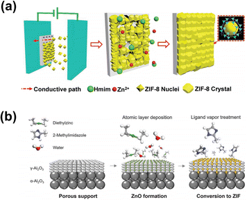 | ||
| Fig. 15 (a) Electrophoretic method followed by the secondary growth. (b) All-vapor-phase processing method for preparing MOF membranes. Reproduced from ref. 132 and 135 with permission. Copyright 2018, Wiley. Copyright 2018, American Association for the Advancement of Science. | ||
He et al. explored the assembly of ZIF-8 seed crystals having strong adhesion on an unmodified support based on the electrophoretic method.132 Wang prepared a “paralyzed” ZIF-8 membrane by a fast current-driven synthesis (FCDS) strategy, which displayed enhanced molecular sieving. The external direct current induces deprotonation of the dimethylimidazole linker and in situ crystallization of the MOF, resulting in fast growth of a continuous membrane layer at room temperature.76 This synthesis method is not only suitable for immobile inorganic substrates like AAO substrates, but also for flexible polymeric substrates having good processability.133
Chemical vapor deposition is the reaction between the solid and gas phases. Li et al. developed a gel-vapor deposition (GVD) method to make membranes with a selective layer thickness down to ∼17 nm. A Zn-based sol was first coated onto the substrate, which was then transformed to a ZIF-8 membrane by vapor–ligand deposition.134 Tsapatsis demonstrated an all-vapor-phase processing method,135 in which ZnO was deposited in the porous support by ALD, followed by vapor–ligand treatment. The obtained ZnO nanocomposite layer exhibited low permeability, but after undergoing ligand–vapor treatment, it was partially transformed to ZIF-8 and showed stable performance. Compared to the solution-phase reaction, metal sources are confined to the outer surface of the substrates, reducing the mobility of metal ions and crack formation.
A variety of polycrystalline MOF membranes have been investigated for the separation of CO2/CH4 and CO2/N2, and a minority of reports indicate properties that outperform polymers. The top-performing MOF membranes reported in the literature for CO2 separation are summarized. According to the structural properties, they are categorized into polycrystalline MOF membranes, 2D MOF membranes and unconventional MOF membranes.
Rui et al.136 reported isoreticular MOF-1 membranes with sharp molecular sieving properties, which showed very high CO2/CH4 and CO2/N2 separation factors of 328 and 410, respectively, and CO2 permeance above 700 GPU. Besides the molecular sieving mechanism, amination of ligands to enhance CO2 adsorption is also an effective means to improve separation. Yin et al.137 developed an amino-functionalized CAU-1 membrane with high permeance and good selectivity. The MOF selective layer was prepared via a secondary growth method with a thickness of 2–3 μm. Influenced by strong amine–CO2 interactions, the permeance of CO2 was higher than that of H2, N2 and CH4, resulting in a permeance of up to 3940 GPU and a CO2/N2 selectivity of 17.4–22.8. Chen et al.138 prepared a series of thin MOF-incorporated organosilica membranes for CO2/CH4 separation. The substrate was first modified by colloidal silica to block larger pores and the MOF/organosilica solution was coated onto the substrate by hot dip-coating. Compared with ZIF-8 and CAU-1, MIL-53-NH2(Al) displayed outstanding performance, which was attributed to CO2 affinity and high adsorption uptake (Fig. 16).
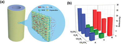 | ||
| Fig. 16 (a) Schematic illustration of a MOF/organosilica nanocomposite membrane on a tubular alumina substrate for gas separation. (b) The selectivity of H2/CH4, H2/N2, CO2/CH4 and CO2/N2 mixed gases through ZIF-8/organosilica (A), MIL-53-NH2/organosilica (B) and CAU-1-NH2/organosilica (C) membranes. Adapted from ref. 138 with permission. Copyright 2017, Royal Society of Chemistry. | ||
Liu et al.139 pioneered the fabrication of a (111)-oriented UiO-66 membrane via oriented tertiary growth. The use of ZrS2 as a metal source during the solvothermal synthesis led to a higher number of missing linkers within the framework and therefore preferential adsorption of CO2 over N2. In comparison with secondary growth, both CO2/N2 selectivity and CO2 permeability of the UiO-66 membrane after tertiary growth were concurrently increased. Apart from single-component MOF membranes, Zhao140 reported multivariate polycrystalline MIL-160/CAU-10-F membranes with remarkable molecular sieving ability. CAU-10-F and MIL-160 are isoreticular Al-MOFs with similar topological structures but different pore window sizes (2.25 Å for CAU-10-F and 4.35 Å for MIL-160). The combination of two MOFs achieved optimization of channel size and polarity. The membranes were fabricated via a mixed-ligand strategy on polydopamine modified α-Al2O3 disks. The multivariate MIL-160/CAU-10-F displayed an obvious enhancement of separation performance with a CO2 permeance of 700 GPU and a CO2/CH4 selectivity of 71 (Fig. 17).
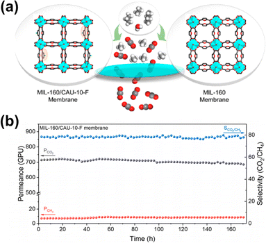 | ||
| Fig. 17 (a) Schematic illustration of a MIL-160/CAU-10-F membrane for gas separation. (b) Long-term separation performance of CO2/CH4. Reproduced from ref. 140 with permission. Copyright 2021, American Chemical Society. | ||
Constructing 2D MOF membranes by 2D nanosheet assembly and crystallization growth is another approach to obtain high-permeability MOF membranes, due to the atomic-scale thickness and low mass transport resistance. Yang et al.141 reported exfoliation of crystalline Zn2(bim)4 by a soft-physical process, in which the crystals were wet ball-milled with a mixture of methanol and propanol at very low speed (60 rpm), followed by ultrasonication. The resulting nanosheets having a large lateral area were nearly one nanometer thick, and were used as building blocks to assemble membranes with outstanding molecular sieving characteristics, with a H2 permeance of up to 2000 GPU and H2/CO2 selectivity >200. The group of Yang further prepared a ZIF-L membrane142 with a membrane-interlocked-support (MIS) composite architecture, in which the ZIF-L membrane was embedded into the substrate and displayed apparent zero thickness. The H2 permeance was above 4000 GPU and the H2/CO2 separation factor was above 200, meeting the industrial target zone. Compared with conventional membranes, the membrane-interlocked-support composite architecture significantly enhanced the mechanical stability and maintained selectivity, even after being subjected to repeated abrasion by silicone rubber as a mechanical challenge test (Fig. 18).
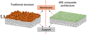 | ||
| Fig. 18 Schematic illustration of the MIS membrane compared with a conventional membrane. Reproduced from ref. 142 with permission. Copyright 2021, Elsevier. | ||
Polycrystalline membranes are prone to the formation of grain boundaries and defects. In this context, Wang143 and Jin et al. prepared a ZIF glass membrane using a melt-quenching method (Fig. 19). The solvothermally synthesized polycrystalline ZIF-62 film was deposited onto an Al2O3 support. The polycrystalline film displayed pinholes and grain boundaries. Upon thermal processing, the ZIF-62 film underwent a phase transition at 440 °C, forming a processable melt. The melt-quenched ZIF-62 glass membrane was smooth and defect-free without any evidence of grain structure. The ZIF-62 glass membrane exhibited short-range order and intrinsic microporosity to small gas molecules, with a CO2 permeability of 2600 barrer and a gas pair selectivity of 34.5 (CO2/N2) and 36.6 (CO2/CH4). Wang et al.144 developed a new class of membranes: metal-induced ordered microporous polymers (MMPs), using polymer chains instead of short organic linkers to form a polymer–hybrid MOF framework. The MMPs featured good control of crystal size and hydrolytic stability. MMP dispersions were first coated onto a flexible modified polysulfone substrate to prepare 50![[thin space (1/6-em)]](https://www.rsc.org/images/entities/char_2009.gif) nm-thick selective layers. The MMPs combined good membrane processability and selectivity suitable for carbon dioxide capture from flue gas. Membranes based on two different MMP structures gave high CO2 permeances of >3000 GPU and >5500 GPU, with the corresponding stable CO2/N2 mixed gas selectivity of 78 and 35, respectively, under both humid and dry gas feed conditions, indicating strong application prospects. Considering the number of different polymer building blocks and metal nodes, there are many opportunities for optimizing new membrane MMP structures.
nm-thick selective layers. The MMPs combined good membrane processability and selectivity suitable for carbon dioxide capture from flue gas. Membranes based on two different MMP structures gave high CO2 permeances of >3000 GPU and >5500 GPU, with the corresponding stable CO2/N2 mixed gas selectivity of 78 and 35, respectively, under both humid and dry gas feed conditions, indicating strong application prospects. Considering the number of different polymer building blocks and metal nodes, there are many opportunities for optimizing new membrane MMP structures.
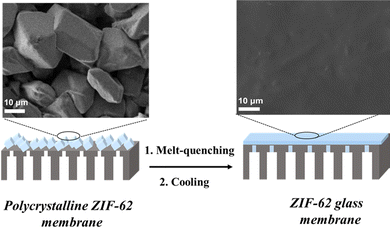 | ||
| Fig. 19 Schematic illustration of the fabrication of the ZIF-62 glass membrane for gas separation. Reproduced from ref. 143 with permission. Copyright 2020, Wiley. | ||
Compared with zeolite membranes, many MOF membranes show a reversible breathing effect under the action of external stimuli such as guest elimination/reintroduction and pressure. For instance, the pore size of ZIF-8 is 0.34 nm, which should theoretically be suitable for CO2/N2 or CO2/CH4 separation. However, the reported ZIF-8 membranes show low selectivity for CO2/N2, but ultrahigh selectivity for C3H8/C3H6. The phenomenon is induced by the rotation of the coordination bond in the framework and the intermolecular degrees of freedom, showing dynamic molecular displacements. In order to constrain the flexibility of the framework, post-synthetic processing has been investigated. Babu et al.145 reported a rapid heat treatment (RHT), in which polycrystalline ZIF-8 membranes were heated at 360 °C for several seconds. Due to the short processing time, the apparent morphology and composition of the membrane were unchanged, but the selectivity of CO2/N2 was significantly improved from 3 to 30, exceeding that of most other polycrystalline MOF membranes.
Most polycrystalline MOFs are difficult to fabricate as self-supporting membranes such as polymeric membranes, and need to be grown on substrates. Membrane–substrate interactions not only affect the preparation of the membranes but also their operational stability. Al2O3 is currently the most commonly used inorganic substrate due to its high chemical and thermal stability. Although there are surface hydroxy groups on alumina, their interaction with most MOFs is still relatively weak, thus demanding further modification during membrane preparation. Recently, some MOF membranes have been prepared on flexible polymer substrates.146,147 Considering the differences in thermal expansion coefficients and mechanical properties between MOFs and polymers, the reaction conditions and the thickness of the membrane should be precisely controlled to avoid damage to the fragile MOF selective layers. Therefore, appropriate modification of the substrates is very important for membrane industrial applications, for which insufficient attention has been paid. In addition, the current MOF membranes are mostly a combination of a single ligand and a single metal ion. The design diversity of MOF materials in the membrane field has not been fully explored or demonstrated. The concept of multiple synergies should also be emphasized, such as mixed metal sites148 and the hybrid assembly of MOF materials and other framework materials.
4.4 COF membranes
COFs are a burgeoning class of crystalline porous materials, constructed from fully organic linkers via covalent bonds. Different from conventional polymers, COFs possess ordered intrinsic pores, uniform pore size distribution and high pore density, owing to the regular and periodical assembly of these organic linkers. Since the first COF material was successfully synthesized via condensation reaction between hexahydroxytriphenylene and diboronic acid in 2005, numerous COFs with diverse structures have been synthesized, based on dynamic covalent chemistry and reticular chemistry. Due to the fine-tuned structures and the tailorable organic linkers, COFs reveal diverse design and functionality.149COF membranes have been developed for nearly 10 years since the first oriented COF-1 film was prepared on single-layer graphene.150 Among the numerous COF materials, β-ketoenamine-linked COF membranes are the most widely studied,151 benefiting from relatively low monomer price and easy manipulation of reaction conditions. Until now, various preparation methods have been exploited to construct high-quality and defect-free COF membranes involving in situ solvothermal synthesis, interfacial polymerization (IP), and self-assembly of the nanosheet.
Caro et al.152 extended the preparation strategy of inorganic membranes to COF membranes. Using in situ solvothermal synthesis, a continuous COF-LZU1 membrane of thickness of nearly 400 nm was prepared on monomer-modified alumina tubes, which exhibited outstanding water permeance and high long-term stability. Banerjee et al.153 reported a simple doctor blade casting method to make a series of self-standing COF membranes. The easy processability provided flexible self-standing COF membranes, free of cracks and stable even in mineral acid (Fig. 20a).
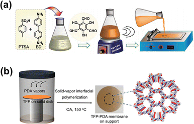 | ||
| Fig. 20 Different methods of preparing COF membranes. (a) Baking of organic linkers and (b) solid–vapor interfacial polymerization. Reproduced from ref. 153 and 155 with permission. Copyright 2017, Wiley. Copyright 2020, American Chemical Society. | ||
Interfacial polymerization, as a common preparation method of polymer membranes, is also suitable for COF membranes (Fig. 20b). Besides liquid–liquid interfaces,154 various other polymerization interfaces are constructed to facilitate the reaction and membrane/film formation, involving solid–liquid interface,150 solid–vapor interface155 and tri-phase interface.78 Dichtel et al.150 prepared a 2D COF-5 film on single-layer graphene by a simple solvothermal method. The solid–liquid interface induced oriented growth and the film revealed higher crystallinity than the powders. Jiang and Wu et al.155 fabricated a highly crystalline COF membrane within 9 h, by an engineered solid–vapor interface. Benefiting from the stability of the solid–vapor interface, the reaction rate was significantly accelerated to 8× faster than that of some reported COFs.
So far, 2D COFs have dominated the majority of COF materials. COF nanosheets are considered as superior precursors to construct membranes by self-assembly. Similar to other 2D materials, COF nanosheets are commonly prepared by either top-down or bottom-up strategies. Li et al.156 fabricated COF-1 membranes by coating exfoliated COF nanosheets onto Al2O3 supports. Compared with conventional in situ growth, the bottom-up technique has some advantages in the manipulation of membrane morphology and thickness. Jiang and Wu et al.157 modified the bottom-up method to coordinate the diffusion and solvent co-mediated modulation of COF growth kinetics. The resulting NUS-9 membranes have crystalline, rigid ion nanochannels exhibiting a weakly humidity-dependent proton conductivity.
COF membrane development is still in its infancy for gas separation and there are far fewer studies on COF membranes than on PIM and MOF membranes. We highlight the outstanding potential of COF membranes, due to their unique architectures and high chemical stability.158
Caro et al.73 first reported a 2D azine-linked COF membrane for CO2/CH4 separation having a high selectivity of 86.3. The membranes were prepared on a PEI-modified substrate, followed by solvothermal synthesis. The membranes were nearly 8 μm thick and exhibited CO2 permeability of about 200 barrer. The intrinsic 0.94 nm pore size is larger than the molecular size of CO2 and CH4. The high selectivity is due to the planar stacking arrangement of COF nanosheets, which provide a narrower channel with molecular sieving ability to reject CH4. Based on similar mechanisms, Zhao et al.159 reported a multi-interfacial engineering strategy to adjust the relatively large-pore COF for small-molecule gas separation. COF membranes were constructed using two COFs (TpPa-SO3H and TpTGCl), which share the same monomer Tp, to minimize the formation of interfacial defects. The membranes were only 155 nm thick, and resulted in an ultrahigh H2 permeance of 2163 GPU and a H2/CO2 selectivity of 26 (Fig. 21). Besides heterogeneous COF structures, Yang et al.160 prepared single-phase COF membranes with CO2-philic channels. The TpPa-2 membranes showed an excellent mixed gas CO2/H2 selectivity of 22 and a CO2 permeance of 328 GPU.
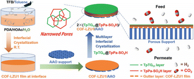 | ||
| Fig. 21 Schematic illustration of the fabrication of the TpPa-SO3H@TpTGCl membrane for gas separation. Reproduced from ref. 159 with permission. Copyright 2021, Wiley. | ||
Apart from adjusting the channel sizes by stacked nanosheets, another strategy is to combine other materials with COFs to construct multi-level transport channels. Qiu et al.161 fabricated two kinds of COF-MOF composite membranes ([COF-300]-[Zn2(bdc)2(dabco)] and [COF-300]-[ZIF-8]). These membranes had an enhanced H2/CO2 selectivity of 12.6 and 13.5, respectively, surpassing the selectivity of the corresponding COF-300, Zn2(bdc)2(dabco), and ZIF-8 membranes. The result was explained by amorphous MOF being doped into the COF layer, which was beneficial for membrane selectivity.
Guiver and Jiang et al.78 explored an oil–water–oil triphase method to fabricate ionic covalent organic framework nanosheets. With DhaTGCl nanosheets as the building block and aspartic acid as the CO2-philic molecule, the membrane displayed a CO2/CH4 selectivity of 78.5 and a CO2 permeance of 143 GPU. It is worth noting that the separation performance remained stable with feed pressures up to 5 bar (Fig. 22). Recently, Meng and Caro et al.162 proposed a MOF-in-COF concept, introducing MOF micro units into COF channels. These membranes exhibited an ultrahigh hydrogen permeance of >3000 GPU and good selectivity for H2/CO2, surpassing the 2008 Robeson upper bounds.
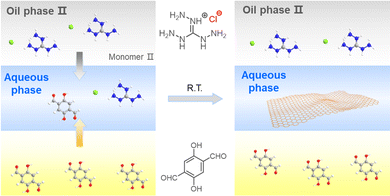 | ||
| Fig. 22 Schematic illustration of the oil–water–oil triphase method. Adapted from ref. 78 with permission. Copyright 2021, Wiley. | ||
COF membranes generally have higher structural stability but lower crystallinity compared with MOF materials. This is the result of the nature of covalent bonds, with bond energies commonly >300 kJ mol−1. In most cases, high bond energy is associated with low reversibility and poor self-healing ability. Therefore, the COF membrane preparation process needs a longer time to improve the crystallinity and make the channel more regular. Although improvements of crystallinity can be achieved by adjusting the preparation parameters, including catalyst, reaction concentration, temperature, etc., the presence of amorphous areas in COF membranes is still unavoidable, even as the main body. To improve crystallinity, it is necessary to develop novel bonding strategies and to reasonably match the reaction process and crystallization. At the same time, the effective distinction between the crystalline phase and the amorphous phase is also very important.
Another topic worth exploring in COF membranes, as a subclass of polymeric membranes, is how to inherit the advantages of conventional polymers that are easy to prepare on a large scale. Recently, Wu and Jiang et al. demonstrated the scalable fabrication of the COF membrane via transformation from the amorphous polymeric membrane to the crystalline phase. The polymeric membrane was fabricated by solution processing followed by monomer replacement to form a regular framework. Further efforts bridging COFs and conventional polymers will enable the design of advanced structures suitable for industrial applications.163
Conclusion and outlook
In this Perspective, we have briefly summarized advanced mechanisms, design principles, and emerging materials, and provided a perspective on the future exploitation of organic microporous membranes for CO2 separation. To gain some intuitive understanding, comparative performance characteristics of representative classes of organic microporous membranes are displayed in Robeson plots in Fig. 23, for the CO2/CH4, CO2/N2 and H2/CO2 mixed gas pairs. PIM membranes have characteristically high CO2 permeability, accompanied by often moderate selectivity, and some exhibit rapid aging. GO/SLG membranes provide a good platform for exploring the construction of ultrathin membranes and confined mass transport mechanisms, while questions about scale up arise. MOF membranes illustrate good separation performance, but their stability under humidified conditions still needs further exploration. COF membranes are still in their infancy, and are expected to broaden the array of materials and related applications. Considering the accelerating environmental concerns, large markets and broad prospects, organic microporous membranes will continue to be a research frontier and hotspot of energy, environment, materials science and chemical engineering within the foreseeable future.Beyond carbon capture, there exist great opportunities, but there are two tough challenges to overcome: (a) development from advanced materials to the scalable fabrication of advanced membranes and (b) applications scale up from laboratory ideal systems to industrial multicomponent mixtures.
From advanced materials to advanced membranes
With the aid of platform chemistries and big data analysis, various advanced materials have been designed and synthesized. According to the requirement, functional precursors are assembled to connect in specific ways to expand into a continuous network or framework. Organic porous materials have been expansively developed in recent years and the utilization of computational screening provides predictive tools beyond trial-and-error. However, advanced materials are not equivalent to advanced membrane materials.164,165 Tested by practical experiments, only a few advanced materials could be used for membrane separation and even fewer, including defect-free membranes, could achieve high performance. Membrane structure is more complex than material structure with new structures derived during the membrane formation process. Thus, the complexity leads to uncertainties in structure–performance relationships, including the bulk structure of the membrane and multiphase interface structures. Gas transport in any given membrane is an overall result, but the mass transport behavior at the crystal interface is often neglected, although it affects or counters the regional separation performance. Defect-free membranes are often examined by SEM, which focuses on morphological information. However, unobservable microdefects and amorphous regions generated during the crystal assembly process also participate in molecular transport together with the membrane bulk. Membrane preparation methods are being improved, which is gradually improving the understanding of membrane formation. Advanced membrane materials not only require high permeability and selectivity, but also need consideration of material uniformity and processability, membrane stability and degradation. While the exploration of preparation methods is the first step in material-to-membrane transition, there is still a long way to go for organic microporous materials to evolve into advanced membranes.From laboratory to practical application
At present, most organic microporous membranes are still at the experimental research stage, and there are some important barriers to be overcome for industrial applications. Firstly, studying realistic mixtures166 will reduce the gap between fundamental studies and practical applications. The majority of the research community for membrane separation focus on single gases or binary mixtures. Studies on idealized mixtures are more appropriate for describing mass transport behavior and material properties, but more complex systems are needed to evaluate practical applications. For instance, flue gas from coal-fired power plants often contains not only CO2, N2, and water vapor, but also ppb–ppm levels of SO2, NO2, and HgCl2. Some contaminants such as SO2 would seriously affect the stability of the membrane structure and water vapor could condense in the channels under high pressure. Another barrier is large-scale membrane fabrication. Polymer membranes are known for their excellent processability and phase inversion for large-scale preparation has been extensively adopted industrially. Apart from solvent-soluble PIMs, other organic microporous materials hardly lend themselves to established fabrication methods, especially for highly crystalline materials. In this context, it is necessary to explore new preparation methods amenable to controllable scale-up. Nature and biomimetic structures may provide inspiration and new ideas to achieve this. Finally, to realize comparison uniformity from laboratory across to industry, some standard reference mixtures should be adopted, including separation components, test conditions, and application requirements.Besides the CCUS process, organic microporous membranes can also show excellent prospects in other applications, such as biogas purification and possibly membrane-based direct air capture. Biogas, a renewable energy resource produced by digestion of biomass, is a water vapor-saturated mixture of CH4 (50–65 vol%), CO2 (30–40 vol%), and traces of H2S, O2, N2, NH3, siloxanes and VOCs. Critically, current biogas separation membranes are predominantly polymer-based, which suffer from materials-related limitations, such as physical aging, plasticization, and permeability–selectivity trade-off. Issues regarding trace impurity components (e.g., H2S, H2O and VOCs) inducing strong competitive adsorption in the polymer matrix have significant consequences in terms of performance deterioration and stability reduction.167 Particularly, microporous materials with ordered, robust and functional framework structures have been used as fillers in membranes and show good potential for the biogas upgrading process. Until now, the separation performance of COF and MOF membranes in the presence of detrimental impurities remains unexplored. It is necessary to understand their structural stability and performance regenerability under realistic mixed feed gas conditions, which include strong competitive adsorption and components that are corrosive to the organic porous materials, to ensure long-term robustness. CCUS is critical to mitigating the energy and environmental crisis, but specific anthropogenic carbon emissions still cannot be eliminated through it. While CO2 capture from more concentrated streams will be a priority, direct air capture (DAC) is an alternative approach to further decreasing the atmospheric CO2 concentration and ultimately achieve negative emission.168 Current DAC technology mainly based on adsorption, absorption and membrane separation, and organic microporous materials represented by MOFs are beginning to attract attention. Eddaoudi et al. reported a fluorinated metal–organic framework (MOF), NbOFFIVE-1-Ni, with high volumetric uptake (51.4 cm3 (STP) cm−3) which can remove trace CO2 efficiently.169 Among all the DAC technologies which have been brought into operation, membrane-based DAC (m-DAC) appears to be the most energy efficient approach. We hope that combining high-performance sorbents with membranes could lead to viable technology. Although the permeability and selectivity of conventional membranes are not currently economically competitive for m-DAC, new materials and structures may lead to viable technology.170,171
Author contributions
Michael D. Guiver and Zhongyi Jiang conceived the Perspective. Yuhan Wang and Haifei Jiang wrote the original draft. Zheyuan Guo, Shaoyu Wang, Hongjian Wang and Shuqing Song collected the data and references. Hanze Ma contributed to the data visualization. Junfeng Zhang and Yan Yin discussed the content. Hong Wu, Zhongyi Jiang and Michael D. Guiver contributed to the writing – review and editing. All authors commented on the Perspective.Conflicts of interest
There are no conflicts to declare.Acknowledgements
The authors gratefully acknowledge financial support from the National Natural Science Foundation of China (No. U20B2023). MDG acknowledges financial support from the State Key Laboratory of Engines (SKLE), Tianjin University, and from the National Industry-Education Platform of Energy Storage, with funding from the National Natural Science Foundation of China (21875161). ZJ and MDG acknowledge financial support from the HaiHe Laboratory of Sustainable Chemical Transformations.Notes and references
- https://gml.noaa.gov/ccgg/trends/, Date accessed: 2022/10/14.
- https://www.iea.org/reports/carbon-capture-utilisation-and-storage-2/, Date accessed: 2022/10/14.
- https://www.globalcarbonproject.org/carbonbudget/index.htm/, Date accessed: 2022/10/14.
- N. M. Dowell, P. S. Fennell, N. Shah and G. C. Maitland, Nat. Clim. Change, 2017, 7, 243–249 CrossRef.
- A. W. Ruttinger, S. Tavakkoli, H. Shen, C. Wang and S. M. Jordaan, Energy Environ. Sci., 2022, 15, 1222–1233 RSC.
- S. E. Zanco, J.-F. Pérez-Calvo, A. Gasós, B. Cordiano, V. Becattini and M. Mazzotti, ACS Eng. Au, 2021, 1, 50–72 CrossRef CAS.
- J. D. Figueroa, T. Fout, S. Plasynski, H. McIlvried and R. D. Srivastava, Int. J. Greenh. Gas Control., 2008, 2, 9–20 CrossRef CAS.
- W. H. Tay, K. K. Lau, L. S. Lai, A. M. Shariff and T. Wang, J. Nat. Gas Sci. Eng., 2019, 71, 102977 CrossRef CAS.
- N. Jusoh, K. K. Lau, Y. F. Yeong and A. M. Shariff, Sains Malays., 2016, 45, 1707–1714 CAS.
- D. S. Sholl and R. P. Lively, Nature, 2016, 532, 435–437 CrossRef PubMed.
- L. M. Robeson, J. Membr. Sci., 2008, 320, 390–400 CrossRef CAS.
- B. Comesaña-Gándara, J. Chen, C. G. Bezzu, M. Carta, I. Rose, M.-C. Ferrari, E. Esposito, A. Fuoco, J. C. Jansen and N. B. McKeown, Energy Environ. Sci., 2019, 12, 2733–2740 RSC.
- H. B. Park, J. Kamcev, L. M. Robeson, M. Elimelech and B. D. Freeman, Science, 2017, 356, eaab0530 CrossRef.
- N. B. McKeown and P. M. Budd, Chem. Soc. Rev., 2006, 35, 675–683 RSC.
- P. M. Budd, B. S. Ghanem, S. Makhseed, N. B. McKeown, K. J. Msayib and C. E. Tattershall, Chem. Commun., 2004, 230–231 RSC.
- S. Kim and Y. M. Lee, Prog. Polym. Sci., 2015, 43, 1–32 CrossRef CAS.
- J. M. Lee and A. I. Cooper, Chem. Rev., 2020, 120, 2171–2214 CrossRef CAS.
- Y. Xu, S. Jin, H. Xu, A. Nagai and D. Jiang, Chem. Soc. Rev., 2013, 42, 8012–8031 RSC.
- Y. Tian and G. Zhu, Chem. Rev., 2020, 120, 8934–8986 CrossRef CAS PubMed.
- S. Xu, Y. Luo and B. Tan, Macromol. Rapid Commun., 2013, 34, 471–484 CrossRef CAS PubMed.
- J. Kim, L. J. Cote and J. X. Huang, Acc. Chem. Res., 2012, 45, 1356–1364 CrossRef CAS PubMed.
- N. Stock and S. Biswas, Chem. Rev., 2012, 112, 933–969 CrossRef CAS PubMed.
- C. S. Diercks and O. M. Yaghi, Science, 2017, 355, eaal1585 CrossRef.
- B. Wang, R. B. Lin, Z. Zhang, S. Xiang and B. Chen, J. Am. Chem. Soc., 2020, 142, 14399–14416 CrossRef CAS.
- N. Du, H. B. Park, M. M. Dal-Cin and M. D. Guiver, Energy Environ. Sci., 2012, 5, 7306–7322 RSC.
- S. Wang, X. Li, H. Wu, Z. Tian, Q. Xin, G. He, D. Peng, S. Chen, Y. Yin, Z. Jiang and M. D. Guiver, Energy Environ. Sci., 2016, 9, 1863–1890 RSC.
- A. G. Slater and A. I. Cooper, Science, 2015, 348, aaa8075 CrossRef PubMed.
- D. L. Gin and R. D. Noble, Science, 2011, 332, 674–676 CrossRef CAS.
- H. Wang, M. Wang, X. Liang, J. Yuan, H. Yang, S. Wang, Y. Ren, H. Wu, F. Pan and Z. Jiang, Chem. Soc. Rev., 2021, 50, 5468–5516 RSC.
- W. Shi and D. R. Luebke, Langmuir, 2013, 29, 5563–5572 CrossRef CAS PubMed.
- W. Cao, G. M. Tow, L. Lu, L. Huang and X. Lu, Mol. Phys., 2016, 114, 2530–2540 CrossRef CAS.
- H. Sui, B.-G. Han, J. K. Lee, P. Walian and B. K. Jap, Nature, 2001, 414, 872–878 CrossRef CAS PubMed.
- R. Kaldenhoff, L. Kai and N. Uehlein, Biochim. Biophys. Acta, 2014, 1840, 1592–1595 CrossRef CAS.
- N. Uehlein, B. Otto, A. Eilingsfeld, F. Itel, W. Meier and R. Kaldenhoff, Sci. Rep., 2012, 2, 538 CrossRef.
- A. W. Thornton, A. Ahmed, S. K. Kannam, B. D. Todd, M. Majumder and A. J. Hill, J. Membr. Sci., 2015, 485, 1–9 CrossRef CAS.
- M. H. C. Knudsen, Ann. Phys., 1909, 28, 75–130 CrossRef CAS.
- J. D. Seader and E. J. Henley, Separation Process Principles, Wiley, New York, 2006 Search PubMed.
- A. Keerthi, A. K. Geim, A. Janardanan, A. P. Rooney, A. Esfandiar, S. Hu, S. A. Dar, I. V. Grigorieva, S. J. Haigh, F. C. Wang and B. Radha, Nature, 2018, 558, 420–424 CrossRef CAS.
- H. Verweij, M. C. Schillo and J. Li, Small, 2007, 3, 1996–2004 CrossRef CAS.
- W. J. Koros and C. Zhang, Nat. Mater., 2017, 16, 289–297 CrossRef CAS PubMed.
- A. Fuoco, C. Rizzuto, E. Tocci, M. Monteleone, E. Esposito, P. M. Budd, M. Carta, B. Comesaña-Gándara, N. B. McKeown and J. C. Jansen, J. Mater. Chem. A, 2019, 7, 20121–20126 RSC.
- S. Yang, Y. Wang, P. Lu, H. Jin, F. Pan, Z. Shi, X. S. Jiang, C. Chen, Z. Jiang and Y. Li, ACS Appl. Mater. Interfaces, 2020, 12, 55308–55315 CrossRef CAS.
- S. Wang, Y. Wu, N. Zhang, G. He, Q. Xin, X. Wu, H. Wu, X. Cao, M. D. Guiver and Z. Jiang, Energy Environ. Sci., 2016, 9, 3107–3112 RSC.
- G. He, S. Huang, L. F. Villalobos, J. Zhao, M. Mensi, E. Oveisi, M. Rezaei and K. V. Agrawal, Energy Environ. Sci., 2019, 12, 3305–3312 RSC.
- P. Q. Liao, D. D. Zhou, A. X. Zhu, L. Jiang, R. B. Lin, J. P. Zhang and X. M. Chen, J. Am. Chem. Soc., 2012, 134, 17380–17383 CrossRef CAS PubMed.
- J. Yan, Y. Sun, T. Ji, C. Zhang, L. Liu and Y. Liu, J. Membr. Sci., 2022, 653, 120496 CrossRef CAS.
- K. Xie, Q. Fu, C. Xu, H. Lu, Q. Zhao, R. Curtain, D. Gu, P. A. Webley and G. G. Qiao, Energy Environ. Sci., 2018, 11, 544–550 RSC.
- X. Liang, H. Wu, H. Huang, X. Wang, M. Wang, H. Dou, G. He, Y. Ren, Y. Liu, Y. Wu, S. Wang, H. Ge, C. Zhong, Y. Chen and Z. Jiang, J. Mater. Chem. A, 2022, 10, 5420–5429 Search PubMed.
- B. Wang, Z. Qiao, J. Xu, J. Wang, X. Liu, S. Zhao, Z. Wang and M. D. Guiver, Adv. Mater., 2020, 32, e1907701 Search PubMed.
- Y. Yuan, Z. Qiao, J. Xu, J. Wang, S. Zhao, X. Cao, Z. Wang and M. D. Guiver, J. Membr. Sci., 2021, 620, 119902 CrossRef.
- X. Q. Cheng, Z. X. Wang, X. Jiang, T. Li, C. H. Lau, Z. Guo, J. Ma and L. Shao, Progr. Mater. Sci., 2018, 92, 258–283 CrossRef CAS.
- Z. Zheng, R. Grunker and X. Feng, Adv. Mater., 2016, 28, 6529–6545 CrossRef CAS.
- H. Li, Z. N. Song, X. J. Zhang, Y. Huang, S. G. Li, Y. T. Mao, H. J. Ploehn, Y. Bao and M. Yu, Science, 2013, 342, 95–98 CrossRef CAS PubMed.
- P. Gorgojo, S. Karan, H. C. Wong, M. F. Jimenez-Solomon, J. T. Cabral and A. G. Livingston, Adv. Funct. Mater., 2014, 24, 4729–4737 CrossRef CAS.
- D. Fritsch, P. Merten, K. Heinrich, M. Lazar and M. Priske, J. Membr. Sci., 2012, 401, 222–231 CrossRef.
- J. Benito, J. Sanchez-Lainez, B. Zornoza, S. Martin, M. Carta, R. Malpass-Evans, C. Tellez, N. B. McKeown, J. Coronas and I. Gascon, ChemSusChem, 2017, 10, 4014–4017 CrossRef CAS.
- M. F. Jimenez-Solomon, Q. Song, K. E. Jelfs, M. Munoz-Ibanez and A. G. Livingston, Nat. Mater., 2016, 15, 760–767 CrossRef CAS.
- R. Castro-Munoz, K. V. Agrawal and J. Coronas, RSC Adv., 2020, 10, 12653–12670 RSC.
- W. C. Lee, L. Bondaz, S. Huang, G. He, M. Dakhchoune and K. V. Agrawal, J. Membr. Sci., 2021, 618, 118745 CrossRef CAS.
- L. P. Ma, W. Ren and H. M. Cheng, Small Methods, 2019, 3, 1900049 CrossRef.
- J. W. Suk, A. Kitt, C. W. Magnuson, Y. F. Hao, S. Ahmed, J. H. An, A. K. Swan, B. B. Goldberg and R. S. Ruoff, ACS Nano, 2011, 5, 6916–6924 CrossRef CAS.
- S. Huang, M. Dakhchoune, W. Luo, E. Oveisi, G. He, M. Rezaei, J. Zhao, D. T. L. Alexander, A. Züttel, M. S. Strano and K. V. Agrawal, Nat. Commun., 2018, 9, 2632 CrossRef.
- Y. B. Yang, X. D. Yang, L. Liang, Y. Y. Gao, H. Y. Cheng, X. M. Li, M. C. Zou, A. Y. Cao, R. Z. Ma, Q. Yuan and X. F. Duan, Science, 2019, 364, 1057–1062 CrossRef CAS PubMed.
- O. M. Yaghi, M. O'Keeffe, N. W. Ockwig, H. K. Chae, M. Eddaoudi and J. Kim, Nature, 2003, 423, 705–714 CrossRef CAS.
- G. He, R. Zhang and Z. Jiang, Acc. Mater. Res., 2021, 2, 630–643 CrossRef CAS.
- H. Wang, Z. Zeng, P. Xu, L. Li, G. Zeng, R. Xiao, Z. Tang, D. Huang, L. Tang, C. Lai, D. Jiang, Y. Liu, H. Yi, L. Qin, S. Ye, X. Ren and W. Tang, Chem. Soc. Rev., 2019, 48, 488–516 RSC.
- Q. Qian, P. A. Asinger, M. J. Lee, G. Han, K. Mizrahi Rodriguez, S. Lin, F. M. Benedetti, A. X. Wu, W. S. Chi and Z. P. Smith, Chem. Rev., 2020, 120, 8161–8266 CrossRef CAS.
- X. Si, C. Jiao, F. Li, J. Zhang, S. Wang, S. Liu, Z. Li, L. Sun, F. Xu, Z. Gabelica and C. Schick, Energy Environ. Sci., 2011, 4, 4522–4527 RSC.
- Y. Jian, H. Yin, F. Chang, L. Cheng, J. Yang, W. Mu, X. Li, J. Lu, Y. Zhang and J. Wang, J. Membr. Sci., 2017, 522, 140–150 CrossRef CAS.
- N. Huang, P. Wang and D. Jiang, Nat. Rev. Mater., 2016, 1, 16068 CrossRef CAS.
- A. P. Côté, A. I. Benin, N. W. Ockwig, M. O'Keeffe, A. J. Matzger and O. M. Yaghi, Science, 2005, 310, 1166–1170 CrossRef.
- Z. Li, X. Feng, Y. Zou, Y. Zhang, H. Xia, X. Liu and Y. Mu, Chem. Commun., 2014, 50, 13825–13828 RSC.
- H. Fan, A. Mundstock, J. Gu, H. Meng and J. Caro, J. Mater. Chem. A, 2018, 6, 16849–16853 RSC.
- H. Dou, M. Xu, B. Wang, Z. Zhang, G. Wen, Y. Zheng, D. Luo, L. Zhao, A. Yu, L. Zhang, Z. Jiang and Z. Chen, Chem. Soc. Rev., 2021, 50, 986–1029 RSC.
- P. J. Bereciartua, A. Cantin, A. Corma, J. L. Jorda, M. Palomino, F. Rey, S. Valencia, E. W. Corcoran, P. Kortunov, P. I. Ravikovitch, A. Burton, C. Yoon, Y. Wang, C. Paur, J. Guzman, A. R. Bishop and G. L. Casty, Science, 2017, 358, 1068–1071 CrossRef CAS PubMed.
- S. Zhou, Y. Y. Wei, L. B. Li, Y. F. Duan, Q. Q. Hou, L. L. Zhang, L. X. Ding, J. Xue, H. H. Wang and J. Caro, Sci. Adv., 2018, 4, eaau1393 CrossRef CAS.
- Z. Qiao, S. Zhao, J. Wang, S. Wang, Z. Wang and M. D. Guiver, Angew. Chem., Int. Ed., 2016, 55, 9321–9325 CrossRef CAS.
- Z. Guo, H. Jiang, H. Wu, L. Zhang, S. Song, Y. Chen, C. Zheng, Y. Ren, R. Zhao, Y. Li, Y. Yin, M. D. Guiver and Z. Jiang, Angew. Chem., Int. Ed., 2021, 60, 27078–27085 CrossRef CAS.
- D. Peng, Y. Liu, S. Wang, Z. Tian, Q. Xin, H. Wu, J. Chen and Z. Jiang, RSC Adv., 2016, 6, 65282–65290 RSC.
- P. M. Budd, E. S. Elabas, B. S. Ghanem, S. Makhseed, N. B. McKeown, K. J. Msayib, C. E. Tattershall and D. Wang, Adv. Mater., 2004, 16, 456–459 CrossRef CAS.
- C. G. Bezzu, M. Carta, A. Tonkins, J. C. Jansen, P. Bernardo, F. Bazzarelli and N. B. McKeown, Adv. Mater., 2012, 24, 5930–5933 CrossRef CAS.
- M. Carta, M. Croad, R. Malpass-Evans, J. C. Jansen, P. Bernardo, G. Clarizia, K. Friess, M. Lanc and N. B. McKeown, Adv. Mater., 2014, 26, 3526–3531 CrossRef CAS.
- R. Short, M. Carta, C. G. Bezzu, D. Fritsch, B. M. Kariuki and N. B. McKeown, Chem. Commun., 2011, 47, 6822–6824 RSC.
- C. G. Bezzu, M. Carta, M.-C. Ferrari, J. C. Jansen, M. Monteleone, E. Esposito, A. Fuoco, K. Hart, T. P. Liyana-Arachchi, C. M. Colina and N. B. McKeown, J. Mater. Chem. A, 2018, 6, 10507–10514 RSC.
- J. Zhang, H. Kang, J. Martin, S. Zhang, S. Thomas, T. C. Merkel and J. Jin, Chem. Commun., 2016, 52, 6553–6556 RSC.
- C. G. Bezzu, A. Fuoco, E. Esposito, M. Monteleone, M. Longo, J. C. Jansen, G. S. Nichol and N. B. McKeown, Adv. Funct. Mater., 2021, 31, 2104474 CrossRef CAS.
- Y. He, F. M. Benedetti, S. Lin, C. Liu, Y. Zhao, H. Z. Ye, T. Van Voorhis, M. G. De Angelis, T. M. Swager and Z. P. Smith, Adv. Mater., 2019, 31, e1807871 CrossRef PubMed.
- S. He, X. Jiang, S. Li, F. Ran, J. Long and L. Shao, AIChE J., 2020, 66, e16543 CrossRef CAS.
- J. W. Jeon, D.-G. Kim, E.-H. Sohn, Y. Yoo, Y. S. Kim, B. G. Kim and J.-C. Lee, Macromolecules, 2017, 50, 8019–8027 Search PubMed.
- R. Swaidan, B. S. Ghanem, E. Litwiller and I. Pinnau, J. Membr. Sci., 2014, 457, 95–102 CrossRef CAS.
- N. Du, H. B. Park, G. P. Robertson, M. M. Dal-Cin, T. Visser, L. Scoles and M. D. Guiver, Nat. Mater., 2011, 10, 372–375 Search PubMed.
- C. R. Mason, L. Maynard-Atem, K. W. J. Heard, B. Satilmis, P. M. Budd, K. Friess, M. Lanč, P. Bernardo, G. Clarizia and J. C. Jansen, Macromolecules, 2014, 47, 1021–1029 CrossRef CAS PubMed.
- C. R. Mason, L. Maynard-Atem, N. M. Al-Harbi, P. M. Budd, P. Bernardo, F. Bazzarelli, G. Clarizia and J. C. Jansen, Macromolecules, 2011, 44, 6471–6479 CrossRef CAS.
- H. A. Patel and C. T. Yavuz, Chem. Commun., 2012, 48, 9989–9991 RSC.
- X. Chen, L. Wu, H. Yang, Y. Qin, X. Ma and N. Li, Angew. Chem., Int. Ed., 2021, 60, 17875–17880 Search PubMed.
- M. Z. Ahmad, R. Castro-Munoz and P. M. Budd, Nanoscale, 2020, 12, 23333–23370 Search PubMed.
- N. B. McKeown, Curr. Opin. Chem. Eng., 2022, 36, 100785 CrossRef.
- H. W. H. Lai, J. M. Ahn, A. M. Robinson, Y. Wang, I. Pinnau, Z. Smith and Y. Xia, Science, 2022, 375, 1390–1392 CrossRef CAS PubMed.
- C. Z. Liang, J. T. Liu, J.-Y. Lai and T.-S. Chung, J. Membr. Sci., 2018, 563, 93–106 Search PubMed.
- M. L. Jue, Y. Ma and R. P. Lively, ACS Appl. Polym. Mater., 2019, 1, 1960–1964 CrossRef CAS.
- I. Borisov, D. Bakhtin, J. M. Luque-Alled, A. Rybakova, V. Makarova, A. B. Foster, W. J. Harrison, V. Volkov, V. Polevaya, P. Gorgojo, E. Prestat, P. M. Budd and A. Volkov, J. Mater. Chem. A, 2019, 7, 6417–6430 Search PubMed.
- A. B. Foster, J. L. Beal, M. Tamaddondar, J. M. Luque-Alled, B. Robertson, M. Mathias, P. Gorgojo and P. M. Budd, J. Mater. Chem. A, 2021, 9, 21807–21823 Search PubMed.
- M. L. Jue, V. Breedveld and R. P. Lively, J. Membr. Sci., 2017, 530, 33–41 CrossRef CAS.
- R. S. Bhavsar, T. Mitra, D. J. Adams, A. I. Cooper and P. M. Budd, J. Membr. Sci., 2018, 564, 878–886 Search PubMed.
- W. H. Lee, J. G. Seong, X. Hu and Y. M. Lee, J. Polym. Sci., 2020, 58, 2450–2466 Search PubMed.
- C. Aguilar-Lugo, C. Álvarez, Y. M. Lee, J. G. de la Campa and Á. E. Lozano, Macromolecules, 2018, 51, 1605–1619 Search PubMed.
- S. Luo, J. Liu, H. Lin, B. A. Kazanowska, M. D. Hunckler, R. K. Roeder and R. Guo, J. Mater. Chem. A, 2016, 4, 17050–17062 Search PubMed.
- Y. S. Do, W. H. Lee, J. G. Seong, J. S. Kim, H. H. Wang, C. M. Doherty, A. J. Hill and Y. M. Lee, Chem. Commun., 2016, 52, 13556–13559 Search PubMed.
- K. S. Novoselov, A. K. Geim, S. V. Morozov, D. Jiang, Y. Zhang, S. V. Dubonos, I. V. Grigorieva and A. A. Firsov, Science, 2004, 306, 666–669 Search PubMed.
- S. Wang, L. Yang, G. He, B. Shi, Y. Li, H. Wu, R. Zhang, S. Nunes and Z. Jiang, Chem. Soc. Rev., 2020, 49, 1071–1089 RSC.
- G. Liu, W. Jin and N. Xu, Angew. Chem., Int. Ed., 2016, 55, 13384–13397 CrossRef CAS PubMed.
- C. N. R. Rao, A. K. Sood, K. S. Subrahmanyam and A. Govindaraj, Angew. Chem., Int. Ed., 2009, 48, 7752–7777 CrossRef CAS PubMed.
- J. S. Bunch, S. S. Verbridge, J. S. Alden, A. M. van der Zande, J. M. Parpia, H. G. Craighead and P. L. McEuen, Nano Lett., 2008, 8, 2458–2462 CrossRef CAS PubMed.
- X. S. Li, W. W. Cai, J. H. An, S. Kim, J. Nah, D. X. Yang, R. Piner, A. Velamakanni, I. Jung, E. Tutuc, S. K. Banerjee, L. Colombo and R. S. Ruoff, Science, 2009, 324, 1312–1314 CrossRef CAS PubMed.
- S. Q. Huang, S. X. Li, L. F. Villalobos, M. Dakhchoune, M. Micari, D. J. Babu, M. T. Vahdat, M. Mensi, E. Oveisi and K. V. Agrawal, Sci. Adv., 2021, 7, eabf0116 CrossRef CAS.
- G. He, S. Huang, L. F. Villalobos, M. T. Vahdat, M. D. Guiver, J. Zhao, W. C. Lee, M. Mensi and K. V. Agrawal, Adv. Funct. Mater., 2020, 30, 202003979 Search PubMed.
- W. S. Hummers and R. E. Offeman, J. Am. Chem. Soc., 1958, 80, 1339 Search PubMed.
- Y. H. Cho, H. W. Kim, H. D. Lee, J. E. Shin, B. M. Yoo and H. B. Park, J. Membr. Sci., 2017, 544, 425–435 Search PubMed.
- S. Kim, H. Wang and Y. M. Lee, Angew. Chem., Int. Ed., 2019, 58, 17512–17527 Search PubMed.
- B. X. Mi, Science, 2014, 343, 740–742 CrossRef CAS PubMed.
- S. Wang, Y. Xie, G. He, Q. Xin, J. Zhang, L. Yang, Y. Li, H. Wu, Y. Zhang, M. D. Guiver and Z. Jiang, Angew. Chem., Int. Ed., 2017, 56, 14246–14251 CrossRef CAS PubMed.
- W. Ying, J. Cai, K. Zhou, D. Chen, Y. Ying, Y. Guo, X. Kong, Z. Xu and X. Peng, ACS Nano, 2018, 12, 5385–5393 Search PubMed.
- F. Zhou, H. N. Tien, W. L. Xu, J. T. Chen, Q. Liu, E. Hicks, M. Fathizadeh, S. Li and M. Yu, Nat. Commun., 2017, 8, 2107 Search PubMed.
- J. Shen, M. Zhang, G. Liu and W. Jin, RSC Adv., 2016, 6, 54281–54285 Search PubMed.
- J. Shen, G. Liu, K. Huang, Z. Chu, W. Jin and N. Xu, ACS Nano, 2016, 10, 3398–3409 Search PubMed.
- J. M. Tuffnell, C. W. Ashling, J. Hou, S. Li, L. Longley, M. L. Rios Gomez and T. D. Bennett, Chem. Commun., 2019, 55, 8705–8715 Search PubMed.
- Z. Kang, L. Fan and D. Sun, J. Mater. Chem. A, 2017, 5, 10073–10091 Search PubMed.
- T. D. Bennett, A. K. Cheetham, A. H. Fuchs and F. X. Coudert, Nat. Chem., 2016, 9, 11–16 CrossRef.
- M. Arnold, P. Kortunov, D. J. Jones, Y. Nedellec, J. Kärger and J. Caro, Eur. J. Inorg. Chem., 2006, 60–64 Search PubMed.
- R. Ranjan and M. Tsapatsis, Chem. Mater., 2009, 21, 4920–4924 CrossRef CAS.
- H. Li, K. Haas-Santo, U. Schygulla and R. Dittmeyer, Chem. Eng. Sci., 2015, 127, 401–417 CrossRef CAS.
- G. He, M. Dakhchoune, J. Zhao, S. Huang and K. V. Agrawal, Adv. Funct. Mater., 2018, 28, 1707427 Search PubMed.
- Y. Zhao, Y. Wei, L. Lyu, Q. Hou, J. Caro and H. Wang, J. Am. Chem. Soc., 2020, 142, 20915–20919 Search PubMed.
- W. Li, P. Su, Z. Li, Z. Xu, F. Wang, H. Ou, J. Zhang, G. Zhang and E. Zeng, Nat. Commun., 2017, 8, 406 Search PubMed.
- X. Ma, P. Kumar, N. Mittal, A. Khlyustova, P. Daoutidis, K. A. Mkhoyan and M. Tsapatsis, Science, 2018, 361, 1008–1011 Search PubMed.
- Z. Rui, J. B. James, A. Kasik and Y. S. Lin, AIChE J., 2016, 62, 3836–3841 Search PubMed.
- H. Yin, J. Wang, Z. Xie, J. Yang, J. Bai, J. Lu, Y. Zhang, D. Yin and J. Y. S. Lin, Chem. Commun., 2014, 50, 3699–3701 Search PubMed.
- C. Kong, H. Du, L. Chen and B. Chen, Energy Environ. Sci., 2017, 10, 1812–1819 RSC.
- J. Yan, Y. Sun, T. Ji, L. Liu, M. Zhang and Y. Liu, J. Membr. Sci., 2021, 635, 119515 Search PubMed.
- W. Fan, Y. Ying, S. B. Peh, H. Yuan, Z. Yang, Y. D. Yuan, D. Shi, X. Yu, C. Kang and D. Zhao, J. Am. Chem. Soc., 2021, 143, 17716–17723 Search PubMed.
- Y. Peng, Y. Li, Y. Ban, H. Jin, W. Jiao, X. Liu and W. Yang, Science, 2014, 346, 1356–1359 CrossRef CAS PubMed.
- K. Yang, S. Hu, Y. Ban, Y. Zhou, N. Cao, M. Zhao, Y. Xiao, W. Li and W. Yang, Sci. Bull., 2021, 66, 1869–1876 Search PubMed.
- Y. Wang, H. Jin, Q. Ma, K. Mo, H. Mao, A. Feldhoff, X. Cao, Y. Li, F. Pan and Z. Jiang, Angew. Chem., Int. Ed., 2020, 59, 4365–4369 CrossRef CAS PubMed.
- Z. Qiao, S. Zhao, M. Sheng, J. Wang, S. Wang, Z. Wang, C. Zhong and M. D. Guiver, Nat. Mater., 2019, 18, 163–168 Search PubMed.
- D. J. Babu, G. He, J. Hao, M. T. Vahdat, P. A. Schouwink, M. Mensi and K. V. Agrawal, Adv. Mater., 2019, 31, e1900855 CrossRef PubMed.
- Z. Qiao, Y. Liang, Z. Zhang, D. Mei, Z. Wang, M. D. Guiver and C. Zhong, Adv. Mater., 2020, 32, e2002165 Search PubMed.
- D. Shi, X. Yu, W. Fan, V. Wee and D. Zhao, Coord. Chem. Rev., 2021, 437, 213794 CrossRef CAS.
- M. Loloei, S. Kaliaguine and D. Rodrigue, Sep. Purif. Technol., 2022, 296, 121391 CrossRef CAS.
- Y. Meng, Y. Luo, J. L. Shi, H. Ding, X. Lang, W. Chen, A. Zheng, J. Sun and C. Wang, Angew. Chem., Int. Ed., 2020, 59, 3624–3629 CrossRef CAS PubMed.
- J. W. Colson, A. R. Woll, A. Mukherjee, M. P. Levendorf, E. L. Spitler, V. B. Shields, M. G. Spencer, J. Park and W. R. Dichtel, Science, 2011, 332, 228–231 Search PubMed.
- S. Yuan, X. Li, J. Zhu, G. Zhang, P. Van Puyvelde and B. Van der Bruggen, Chem. Soc. Rev., 2019, 48, 2665–2681 Search PubMed.
- H. Fan, J. Gu, H. Meng, A. Knebel and J. Caro, Angew. Chem., Int. Ed., 2018, 57, 4083–4087 Search PubMed.
- S. Kandambeth, B. P. Biswal, H. D. Chaudhari, K. C. Rout, H. S. Kunjattu, S. Mitra, S. Karak, A. Das, R. Mukherjee, U. K. Kharul and R. Banerjee, Adv. Mater., 2017, 29, 28066986 Search PubMed.
- K. Dey, M. Pal, K. C. Rout, H. S. Kunjattu, A. Das, R. Mukherjee, U. K. Kharul and R. Banerjee, J. Am. Chem. Soc., 2017, 139, 13083–13091 Search PubMed.
- N. A. Khan, R. Zhang, H. Wu, J. Shen, J. Yuan, C. Fan, L. Cao, M. A. Olson and Z. Jiang, J. Am. Chem. Soc., 2020, 142, 13450–13458 CrossRef CAS.
- G. Li, K. Zhang and T. Tsuru, ACS Appl. Mater. Interfaces, 2017, 9, 8433–8436 Search PubMed.
- L. Cao, H. Wu, Y. Cao, C. Fan, R. Zhao, X. He, P. Yang, B. Shi, X. You and Z. Jiang, Adv. Mater., 2020, 32, 2005565 CrossRef PubMed.
- R. Wang, J. Guo, J. Xue and H. Wang, Small Struct., 2021, 2, 2100061 Search PubMed.
- Y. Ying, S. B. Peh, H. Yang, Z. Yang and D. Zhao, Adv. Mater., 2021, 2104946 Search PubMed.
- P. Wang, Y. Peng, C. Zhu, R. Yao, H. Song, L. Kun and W. Yang, Angew. Chem., Int. Ed., 2021, 60, 19047–19052 CrossRef CAS.
- J. Fu, S. Das, G. Xing, T. Ben, V. Valtchev and S. Qiu, J. Am. Chem. Soc., 2016, 138, 7673–7680 CrossRef CAS PubMed.
- H. Fan, M. Peng, I. Strauss, A. Mundstock, H. Meng and J. Caro, Nat. Commun., 2021, 12, 38 CrossRef CAS.
- C. Y. Fan, H. Wu, J. Y. Guan, X. D. You, C. Yang, X. Y. Wang, L. Cao, B. B. Shi, Q. Peng, Y. Kong, Y. Z. Wu, N. A. Khan and Z. Y. Jiang, Angew. Chem., Int. Ed., 2021, 60, 18051–18058 CrossRef CAS.
- U. Beuscher, E. J. Kappert and J. G. Wijmans, J. Membr. Sci., 2022, 643, 119902 Search PubMed.
- M. D. Guiver, Front. Membr. Sci. Techn., 2022, 1, 878879 CrossRef.
- D. S. Sholl and R. P. Lively, JACS Au, 2022, 2, 322–327 Search PubMed.
- E. Esposito, L. Dellamuzia, U. Moretti, A. Fuoco, L. Giorno and J. C. Jansen, Energy Environ. Sci., 2019, 12, 281–289 RSC.
- E. S. Sanz-Perez, C. R. Murdock, S. A. Didas and C. W. Jones, Chem. Rev., 2016, 116, 11840–11876 CrossRef CAS PubMed.
- P. M. Bhatt, Y. Belmabkhout, A. Cadiau, K. Adil, O. Shekhah, A. Shkurenko, L. J. Barbour and M. Eddaoudi, J. Am. Chem. Soc., 2016, 138, 9301–9307 CrossRef CAS PubMed.
- R. Castro-Munoz, M. Z. Ahmad, M. Malankowska and J. Coronas, Chem. Eng. J., 2022, 446, 137047 Search PubMed.
- S. Fujikawa and R. Selyanchyn, MRS Bull., 2022, 47, 416–423 Search PubMed.
Footnote |
| † These authors contributed equally to this work. |
| This journal is © The Royal Society of Chemistry 2023 |


