DOI:
10.1039/D3IM90006A
(Correction)
Ind. Chem. Mater., 2023,
1, 620-625
Correction: Lithium-mediated electrochemical dinitrogen reduction reaction
Received
27th April 2023
, Accepted 27th April 2023
First published on 19th May 2023
Abstract
Correction for ‘Lithium-mediated electrochemical dinitrogen reduction reaction’ by Muhammad Saqlain Iqbal et al., Ind. Chem. Mater., 2023, DOI: https://doi.org/10.1039/D3IM00006K.
The authors regret that the incorrect permissions were provided in the figure captions of Fig. 1–15 in the original article. The correct versions of the figures, including the updated permissions, are shown below.
|
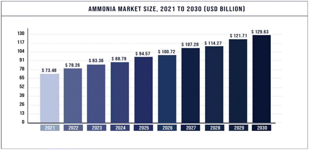
| Fig. 1 Projected global ammonia demand growth from 2021 to 2030.2 Copyright 2023, Precedence Research. | |
|
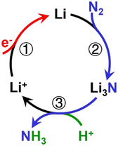
| Fig. 2 Mechanism of catalytic recycling of lithium intermediates. Reproduced with permission.23 Copyright 2021, Wiley-VCH. | |
|
| Fig. 3 (a) A ‘Heterogeneous mechanism’, in which there is a stable amount of lithium on the electrode at all times; (b) free energy diagram of NH3 formation on the surfaces of Li, Li3N, and LiH. The free energy diagram is represented through dash lines when the limiting potential is switched on. All of these surfaces are active for NH3 synthesis. Reproduced with permission.41 Copyright 2020, Wiley-VCH. | |
|
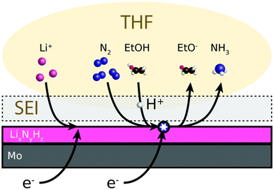
| Fig. 4 Schematic of the mechanism for Li-eN2RR to NH3. A non-aqueous electrolyte (THF) contains lithium salt which is electrodeposited onto a metal electrode (Mo) as metallic Li. Reproduced with permission.38 Copyright 2020, Royal Society of Chemistry. | |
|
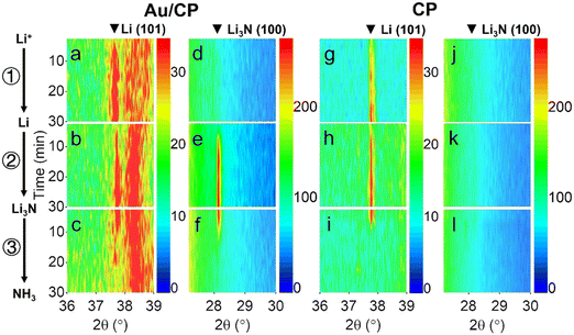
| Fig. 5
In situ XRD contour maps of (a) and (d) Au/CP and; (g) and (j) CP under Ar atmosphere; (b) and (e) Au/CP and (h) and (k) CP under N2 atmosphere without EtOH; (c) and (f) Au/CP and (i) and (l) CP under N2 atmosphere with EtOH. Reproduced with permission.23 Copyright 2021, Wiley-VCH. | |
|
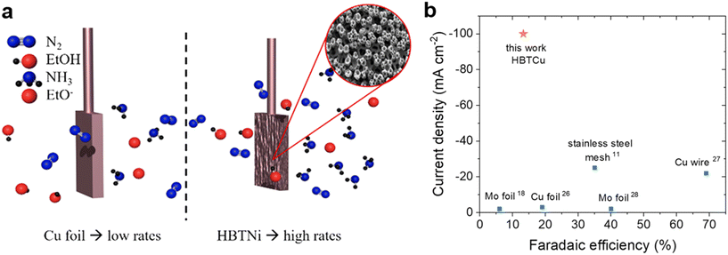
| Fig. 6 (a) Illustration of Cu foil and HBT Cu for Li-mediated eN2RR; (b) comparison of HBT Cu and previously reported electrode materials in terms of current density and NH3 FE. Reproduced with permission.58 Copyright 2022, American Chemical Society. | |
|
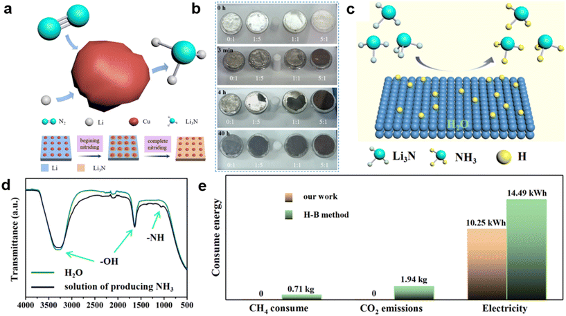
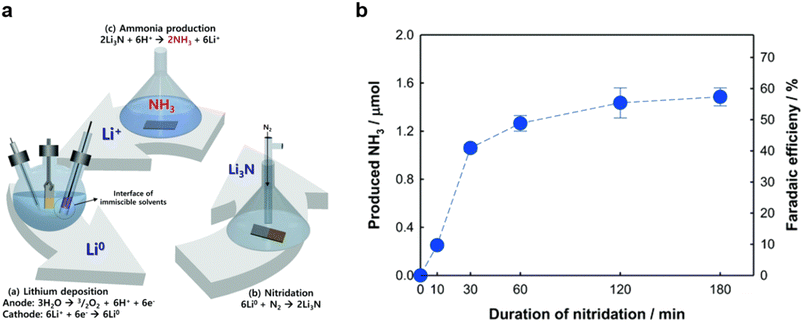
| Fig. 7 (a) Illustration of Cu-catalyzed lithium nitridation (top panel) and steps for the formation of Li3N/Cu from Li/Cu (bottom panel); (b) catalytic effect of Cu-to-Li mass ratio on the nitridation process; (c) illustration of NH3 synthesis from the reaction of Li3N and H2O; (d) infrared spectra of H2O and the electrolyte solution after reaction; (e) comparison of this work with the H–B process in terms of energy consumption for production of 1 kg of NH3. Reproduced with permission.14 Copyright 2022, American Chemical Society. | |
|
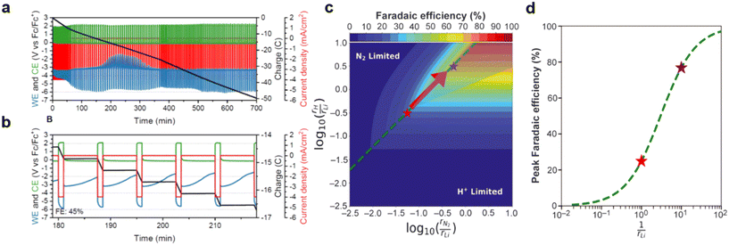
| Fig. 8 (a) Cycling method between −2.0 and 0.0 mA cm−2 (red) for a total of 100 C of charge passed (black); (b) a close-up of the cycling; reproduced with permission.38 Copyright 2020, Royal Society of Chemistry; (c) heatmap of the predicted FE against the ratio of N2 to lithium (x axis) and proton to lithium (y axis) diffusion rates; (d) a one-dimensional plot of NH3 FE cut along the optimal rN2/rH ratio. Reproduced with permission.59 Copyright 2021, American Association for the Advancement of Science. | |
|
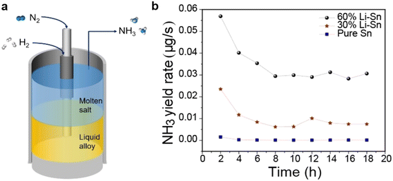
| Fig. 9 (a) Graphical illustration of Li-eN2RR containing Li–Sn alloy and molten LiCl–KCl salt forming a biphasic system; (b) NH3 yield rate against electrolysis time on Li–Sn and pure Sn. Reproduced with permission.62 Copyright 2021, Wiley-VCH. | |
|
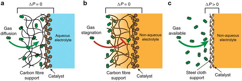
| Fig. 10 (a) A hydrophobic GDE with an aqueous electrolyte; (b) a hydrophobic GDE with a non-aqueous electrolyte; (c) a catalyst-coated (SSC) GDE with a non-aqueous electrolyte. Reproduced with permission.22 Copyright 2020, Springer Nature. | |
|
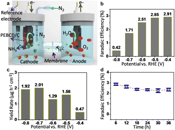
| Fig. 11 (a) The graphic illustration of the configuration of the electrochemical cell for the eN2RR process; (b) FEs of the Li+-PEBCD/CC catalyst at different potentials during the eN2RR; (c) NH3 yield rate against applied potential during the eN2RR; (d) durability test results for Li+-PEBCD/CC. Reproduced with permission.3 Copyright 2017, American Chemical Society. | |
|
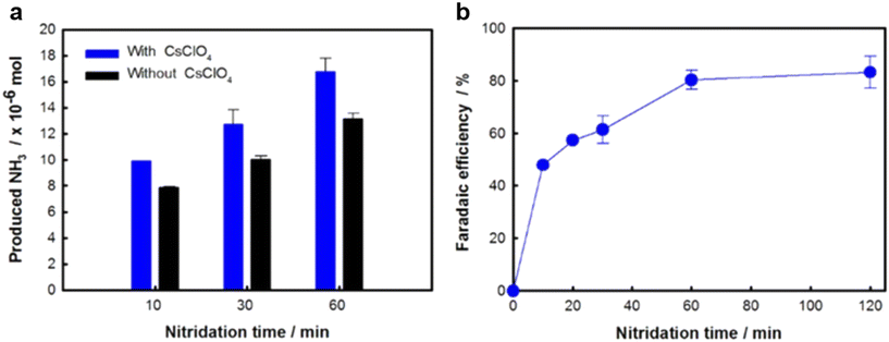
| Fig. 12 (a) NH3 yield and (b) NH3 FE in the presence and absence of 0.03 M CsClO4 at 220 °C over time. Reproduced with permission.8 Copyright 2018, IOP Publishing. | |
|
| Fig. 13 (a) Schematic diagram and (b) NH3 yield and FE of the biphasic hybrid catalytic system catalyzed by LiClO4 (aq) and LiClO4–PMMA composite. Reproduced with permission.66 Copyright 2019, Royal Society of Chemistry. | |
|
| Fig. 14 (a) Schematic illustration of eN2RR catalysis using a phosphonium salt; (b) NH3 yield and FE as a function of time. Reproduced with permission.24 Copyright 2021, American Association for the Advancement of Science. | |
|
| Fig. 15 (a) Expanded view of the continuous-flow electrolyzer configuration; (b) schematic process of the Li-NRR in a continuous-flow electrolyzer. Reproduced with permission.72 Copyright 2023, American Association for the Advancement of Science. | |
The Royal Society of Chemistry apologises for these errors and any consequent inconvenience to authors and readers.
|
This journal is © Institute of Process Engineering of CAS 2023 |
Click here to see how this site uses Cookies. View our privacy policy here.