
 Open Access Article
 This Open Access Article is licensed under a
 Creative Commons Attribution 3.0 Unported Licence
A single-molecule study on polymer fluid dynamics in porous media†
Antonia
Sugar‡
a,
Maged
Serag
b,
Ulrich
Buttner
 c,
Satoshi
Habuchi
*b and
Hussein
Hoteit
*a
c,
Satoshi
Habuchi
*b and
Hussein
Hoteit
*a
aPhysical Science and Engineering Division, King Abdullah University of Science and Technology (KAUST), Thuwal, Saudi Arabia. E-mail: Hussein.hoteit@kaust.edu.sa
bBiological and Environmental Science and Engineering Division, King Abdullah University of Science and Technology, Thuwal, Saudi Arabia. E-mail: satoshi.habuchi@kaust.edu.sa
cNanofabrication Core Lab, King Abdullah University of Science and Technology, Thuwal, Saudi Arabia
First published on 23rd August 2023
Abstract
Understanding the dynamic behavior of polymeric fluids in porous media is essential for vast geoscience applications, particularly enhanced oil recovery and polymer-enhanced soil washing, to clean up soil contamination. During the past decades, the behavior of polymeric fluids in microscopic space has only been investigated using ensemble-averaged experimental methods in which a bulk phase behavior of the fluids characterizes flow mechanisms. Multiple flow mechanisms have been proposed based on ensemble-averaged data; however, microscale characterization of the interactions between polymers and solid surfaces and the mechanisms governing polymer retention and permeability reduction as well as the reversibility of polymer retention are lacking, resulting in a limited understanding of the flow mechanisms. Here we report direct visualization and multi-scale characterization of the dynamic behavior of polymer molecules in a representative porous medium by integrating microfluidics with single-molecule imaging. We demonstrate that the polymers' adsorption, entrapment and hydrodynamic retention contribute to their overall retention in porous media. Our study illustrates how microfluidics can help in understanding the dynamic behavior of polymers, their interactions with the solid/fluid interface and their effects on flow properties. Additionally, it demonstrates the role of microfluidic platforms in providing a more representative and accurate model for polymer retention and permeability reduction in porous media. The obtained insights encourage the development of improved models that better capture the behavior of complex fluids in confined environments and have significant implications for a wide range of applications in geoscience, materials science, and rheology.
Introduction
The flow of complex fluids,1 such as polymers, colloids, gels, liquid crystals, and other materials with flowable microstructures, in porous media is ubiquitous.2 The flow processes of complex fluids are relevant to a broad spectrum of applications ranging from enhanced oil recovery in the geoscience and petroleum industries,3 aquifer remediation,4 and solute transport in the sub-surface in environmental science to filtration and chemical processes in chemistry5–7 and the flow of blood and interstitial fluids in biology.8–21 The ubiquity and relevance of these flow processes have thus propelled the use of microfluidics as a valuable tool enabling precise control and microscopic visualization. This facilitated the study and understanding of the underlying physical phenomena associated with complex fluids in porous media.9Of particular importance, to meet the global energy demand, petroleum industries have used polymers for enhanced oil recovery (EOR) from reservoir rocks having complex, microscopic porous structures.22 Adding water-soluble polymers to the injected water generates a non-Newtonian fluid that exhibits shear viscosity and complex fluid–rock interactions that promote efficient oil recovery.23 The flow behavior of polymers in porous rocks has been thoroughly studied in the literature since the 1970s.24–26 However, polymer static and dynamic retention processes important for EOR and their reversibility are not entirely understood.24,27–30 This insufficient understanding is due to the absence of microscale experimental investigations and direct visualisation. A theoretical model that describes polymer retention has been developed. Three main mechanisms are presumed to contribute to the overall retention of polymers: polymer adsorption, hydrodynamic retention, and mechanical entrapment (Fig. 1a).3,31 In this theoretical model, adsorption is defined by the attachment of polymer molecules in the aqueous phase to the solid surface, driven by van der Waal's and hydrogen bonding rather than by chemisorption.32–34 Mechanical entrapment occurs when larger polymer molecules become lodged within narrow flow channels.17–19,35–37 Hydrodynamic retention is defined by the entrapment of polymers in stagnant zones, dead-end pores, or secondary flow zones at the microscopic pore-scale level.38–40 These three mechanisms were, however, hypothesized based on core-flood experiments, a conventional method to characterize fluid flow, rather than on direct experimental visualization. The core-flood experiments can measure only the cumulative polymer retention in a rock, inferred from pressure drop across the core and effluent concentration profiles,41 and thus provide little insight into the molecular-scale mechanisms of polymer retention. In addition, this approach often results in overestimated adsorption because the three forces (i.e., adsorption, mechanical entrapment, and hydrodynamic retention) contribute differently as a function of flow velocity. Thus, the current theoretical model fails to explain the individual flow velocity dependency and reversibility behavior in a complex fluid flow.
 | ||
| Fig. 1 Experimental design used to study the polymer retention mechanism. (a) A schematic illustration of polymer retention mechanisms in porous formations. (b) Schematic illustration of the microfluidic device structure. The pattern of the flow units is shown in the middle, whereas the channels within one flow unit are shown on the right. (c) Chemical structure of poly(fluorescein isothiocyanate allylamine hydrochloride. (d) Dry-phase atomic force microscopy topographic micrograph of the polymer molecules. (e and f) Dynamic light scattering histograms showing hydrodynamic diameter versus volume % (e) and the corresponding number % (f) of polymer molecules and their agglomerates. (g) A representative fluorescence image of polymer molecules flowing inside the microchannels. (h–j) The acquired greyscale images (g) were converted to RGB scale for enhanced visualization purposes. The series of images illustrate the flowing water in blue, the polymer molecules in green, and the polymer agglomerates in red. The images were captured at 28 frames per second. The white arrow shows the flow direction. Scale bar = 50 μm. | ||
Optically transparent microfluidics in conjunction with fluorescence microscopy has been used as a tool to mimic pore-scale flow phenomena for the past decade.11 Microfluidics provides a convenient approach for the replication of porous networks and direct visualization of complex fluid dynamics at the pore scale.8–10 Conventionally, bulk methods have been used to study fluid flow, where fluorescent tracing particles are embedded within the fluid.12–17 Based on the assumption that the tracer particles move along the flow streams, the fluid behavior is indirectly assessed from the dynamics of the tracer particles. More recently, flow experiments in microfluidic devices have also been used to assess different aspects of polymer flow, including sweep efficiency, flow divergence, recovery factor, and others.42–48 However, none of the previous studies directly captured polymer retention at the molecular level. In addition, bulk methods, which average away the behavior of individual molecules,18 failed to capture the underlying phenomena at the molecular level at different time and length scales.49 Therefore they failed to provide essential insight into intra-fluid, fluid–fluid, or fluid–surface interactions, as these interactions eventuate at the molecular scale. To date, flow mechanisms such as adsorption, diffusion, dispersion, and clustering of molecules, among others, have not been assessed directly with the conventional approach.
In this study, we developed an experimental and analytical workflow that combines microfluidics with single-molecule tracking to investigate the dynamics of fluorescently labeled polymer molecules in a porous medium (Fig. 1a and b). The miniaturized setup of our approach enables precise control of flow parameters and direct visualization of fluid flow at the pore scale, offering valuable insights into the dynamic behavior of polymer molecules and their interactions with the solid/fluid interface. Moreover, microfluidics and single-molecule microscopy allow us to track individual trajectories of polymer agglomerates and their velocity profiles. By employing this workflow, we provide a detailed molecular-level description of polymer retention mechanisms in porous media, which has been largely unexplored.
Results
Experimental design
The designed microfluidic chips, fabricated in PDMS (Fig. 1b), serve as a two-dimensional proxy to avoid the complexity of the three-dimensional porous network in rocks, which facilitate isolating and visualizing the pore-scale mechanisms. The wettability of PDMS can be likened to that of hydrophobic rocks, such as certain shales, carbonates, oil sands, and altered oil-bearing sandstones that exhibit hydrophobic mineral composition or surface roughness. This resemblance between PDMS and hydrophobic rocks makes PDMS a suitable material for studying and replicating the wettability characteristics of such rocks.47 The dimensions of the microfluidics device are 1 cm × 2 cm; each flow unit is 150 μm in width and 72 μm in height. The flow unit structure is symmetrical towards the horizontal axis and consists of 5 channels with apertures of 10, 5, 2, 5, and 10 μm, respectively (Fig. 1b). The configuration of the 2D pore structure micromodel has been designed to mimic the heterogeneous nature of rock pore throats with 5 parallel channels ranging from 2 to 10 μm, mimicking the pore-size distribution of natural rocks (0.1–10 μm)49 (see the Methods section for the detailed experimental procedures).We used a cationic fluorescently labeled polymer, poly(fluorescein isothiocyanate allylamine hydrochloride), with a molecular weight of 56 kDa as the flowing polymeric material at a concentration of 10 μg mL−1 in an aqueous solution (Fig. 1c and d; see ESI† Text I and Fig. S1). We acknowledge that fluorescein is known to have different protonation states depending on the solution's pH, and each protonation form has a different fluorescence brightness. In general, a slightly basic pH is used for fluorescence imaging experiments with fluorescein (around pH 8–9) so that the fluorescent form is dominant in the solution. Our imaging experiment on the polymer solution was conducted using pure water, which may affect the fluorescence brightness of the labeled polymer molecules. However, in our fluorescence microscopy experiments, we obtained a high signal-to-background ratio in water, particularly from polymer agglomerates, as demonstrated in Fig. 1g. This allowed us to quantitatively analyze the retention of the polymer. Therefore, the effect of potentially diminished fluorescence brightness under the imaging conditions on our analysis is negligible. We note that the choice to use pure water instead of a buffer solution is aligned with the industrial application of polymer flooding in the oil field. The polymer is typically injected into the reservoir as an aqueous solution without adding a buffer in this application.
The hydrodynamic size of the polymer molecules was measured by dynamic light scattering. The hydrodynamic diameter (Fig. 1e and f) showed a bimodal distribution centered at about 60 nm (individual polymer molecules with almost 100% relative abundance) and 4000 nm (polymer agglomerates, with minimal abundance, yet dominant by volume). The results of the hydrodynamic size measurement of polymers and the low abundance of polymer agglomerates compared to the polymer molecules are consistent with the direct observation of the polymer solution imaged during flow experiments by the epifluorescence microscopy setup (Fig. 1g-j). The calculated radius of gyration (Rg) of a single polymer molecule is 9.25 nm (see ESI† Text II).
The integration of microfluidics and single-molecule tracking aims at achieving detailed visualization of the hypothesized dynamics of polymer retention, namely polymer adsorption, mechanical entrapment, and hydrodynamic retention. Polymer adsorption, driven by fluid–rock surface forces, may occur at both static and dynamic conditions, while hydrodynamic retention and mechanical entrapment occur exclusively at dynamic conditions. This study focused mainly on the dynamic aspect of polymer retention as their nature and physical behavior have remained unresolved in the literature for decades.
Dynamics of polymer adsorption
Unlike the dynamic components of polymer retention, static polymer adsorption in reservoir rocks has been extensively studied.27,32,50–65 We assessed the static adsorption in our experiments to investigate whether it affects the dynamic processes. ESI† Fig. S2 shows that the static adsorbed polymers significantly modified the area available for the flow as soon as the polymer molecules saturated the PDMS surface within 1–2 h of continuous flow. The adsorbed molecules formed non-uniform adsorption layers with 1–5 μm thickness which resulted in either partial or complete channel clogging (see below). The clogging of the 2 μm flow channels (ESI† Fig. S1a) and the 5 μm flow channels (ESI† Fig. S1b) results from flow-induced adsorption.57 However, the flow experiment also showed reversible adsorption with unclogging of the partially and completely clogged channels (Fig. 2). As previously demonstrated,50 adsorbed polymer agglomerates in partially clogged channels were eluted during the flow via flow-induced desorption (Fig. 2a–c and ESI† Video S1). | ||
| Fig. 2 Adsorption and dynamic desorption of the polymer agglomerates inside microchannels. (a and b) Time-lapse images showing the entrapment reversibility of a partially clogged channel, marked within the white box. The clogging by polymer agglomerates is shown and followed by the release of polymers in (b). The flow path across the adsorption area is 10 μm. (c) Normalized mean pixel intensity (NPI) in the area marked with the white box in (a) and (b). The red line marks a drop in fluorescence intensity concomitant with the desorption of polymer agglomerate. (d) Cumulative NPI of intensity fluctuations after desorption (i.e. fluorescence intensity fluctuation past the red line in (c). The red lines show the piecewise linear fitting of the cumulative NPI. | ||
The temporal variation of relative mean pixel intensity in the adsorption area showed abrupt decrease in fluorescence intensity as soon as the adsorbed polymer agglomerates are liberated (dashed red line in Fig. 2c). Afterwards, the cumulative mean pixel intensity of flowing polymer molecules (green color in Fig. 2b, see also the RGB color coding in Fig. 1h–j) in the adsorption area (Fig. 2a; the white square) showed fluctuations with multi-flow rates that ranged between 1.4 and 58 μm s−1 (Fig. 2d). This speed range, obtained from fluorescence intensity fluctuations, is in agreement with that obtained from single-particle tracking of flowing polymer molecules and their agglomerates inside the flow units (see below, Fig. 6d). Subsequent to channel unclogging, the speed of polymer molecules in the adsorption area increased (up to 58 μm s−1) and then gradually decreased until reaching 1.4 μm s−1 (the speed range of hindered flow, see below and Fig. 6d). This indicated an irregular flow pattern due to desorption and re-adsorption of single polymer molecules. This fluctuation was theoretically predicted from core flood experiments,28 but not experimentally observed as a multistep dynamic process where it can be attributed to the dynamic interplay between the polymer agglomerates and the microchannel structure. When the polymer agglomerates interact with the channel walls or encounter other agglomerates, they experience changes in their motion and velocity. These interactions could result in temporary obstructions or rearrangements of agglomerates within the flow, leading to velocity fluctuations. This rearrangement can be influenced by factors such as the size and distribution of the agglomerates, the flow rate, and the local hydrodynamic conditions. It has also been postulated that the hydrodynamic forces develop at the adsorption site until they become large enough to drive the macromolecules over the osmotic barrier of the ‘static’ adsorbed layer.64 Possible factors that govern the unclogging process in microfluidic channels include fluid dynamics, shear stress, polymer properties, channel geometry, cohesive and adhesive forces, agglomerate microstructure (i.e. compactness), and intermolecular interactions between the polymer and the chip material. Capturing this phenomenon is challenging due to sudden and unexpected occurrence, which emphasizes the need for further research to understand the underlying mechanisms and dynamics of unclogging in microfluidic systems.
Unlike partial clogging, complete clogging of microscale pores was believed to be irreversible.28,62,64 We show, however, that completely clogged channels exhibit the same reversibility as partially clogged ones with flow restoration after unclogging (Fig. 3a–c and ESI† Video S2). Time-lapse fluorescence images (Fig. 3a–d) show that the polymer agglomerates at the clogged site (Fig. 3a) and disaggregates into smaller fragments (Fig. 3b), hence triggering channel unclogging (Fig. 3c). The temporal fluctuation of fluorescence intensity in the adsorbed area of the top channel (Fig. 3d, blue line) showed a sudden increase in intensity at around 17 s, which corresponds to the disaggregation and unclogging of the channel. In contrast, the bottom channel exhibited a uniform trend in the temporal fluctuation of fluorescence intensity (Fig. 3d, red line), indicating a relatively constant polymer flow. These results provide direct evidence that the adsorption of the polymers can be a dynamic component of polymer retention, even when the pores are completely clogged.64 It was observed that the thickness of the polymer adsorption layer in both static and dynamic conditions is highly dependent on the shear rate. A critical shear rate of 70 s−1 was identified, below which the adsorbed layer thickness remained nearly constant and below 1 μm. However, above this critical shear rate, the layer thickness exhibited a significant increase with the shear rate, reaching a maximum value of approximately 2 μm. We posit that the clogging polymer agglomerates remain permeable to the aqueous phase, which may eventually lead to the removal of trapped molecules after the flow-induced disaggregation.
 | ||
| Fig. 3 Reversibility of polymer entrapment. (a–c) Time-lapse images showing the entrapment reversibility of a completely clogged channel, marked by white arrows. (d) Temporal fluctuation of fluorescence intensity in the adsorption area of the top channel marked with arrows in (a)–(c) (blue line) in comparison with the same area of the bottom channel (red line). | ||
Mechanical entrapment
Mechanical entrapment reflects the dynamic component of polymer retention that occurs when polymer molecules are trapped in narrow flow channels relative to the polymer molecule size. Fig. 4a–f show integrated images of the time-lapse fluorescence images captured during the time periods indicated in each panel (see ESI† Video S3). Tracking the particle pathways reflecting the streamlines allows visualizing the overall flow of the molecules and aggregates in the channels. The top 10 μm channel (Fig. 4a–d) initially showed an open flow (Fig. 4g, Stage I), followed by clogging caused by strangulation (Fig. 4e, f and g, Stage II). The clogged area appears in blue (dotted rectangle in Fig. 4e and f) with low fluorescence levels, caused by the stalled polymeric material. The agglomerate entrapment occurred in the restriction, as the available section to flow was too small relative to the size of the flowing polymer agglomerate (Fig. 4e). | ||
| Fig. 4 Entrapment of polymer molecules in microchannels. (a–f) Integrated images of the time-lapse fluorescence images captured during the time periods indicated in each panel. The arrows in (e) and (f) illustrate the clogging of the 10 μm channel by molecular clusters. Scale bar: 50 μm. (g) Temporal fluctuation of the relative mean pixel fluorescence intensity obtained from the area highlighted by the dashed rectangle in (a)–(f). | ||
These results provide direct evidence that the complete clogging of the 10 μm channel was caused by a polymer of molecule size around 60 nm due to polymer agglomeration (Fig. 1e), even though the polymer molecule does not show a high tendency to aggregate (Fig. 1f). Importantly, complete clogging leads to flow divergence, reducing the porosity and conductivity of the medium, and creating inaccessible pore volume that could account for up to 40% of the total pore volume.38,58 Our observation controverts the commonly used rule of thumb to select the polymer molecular size to be five times smaller than the average pore throat size of the rock pore network. This finding emphasizes polymer aggregation as a critical factor to be taken into account in polymer screening, even though the aggregation tendency is very low.
It is important to underline that the clogging of the flow channels occurred due to a combination of two processes: adsorption and mechanical entrapment. However, because we were unable to capture the exact moment of clogging during chip saturation and the initial 1–2 hours of flow, where retention happens quickly, we could not separate the individual contributions of adsorption and mechanical entrapment. As a result, we grouped them together based on the final outcome, which was the complete clogging of the flow channels caused by the combined effect of adsorption and mechanical entrapment (Fig. 3 and 4). To characterize this behavior, we analyzed the polymer flow in 104 flow units (ESI† Fig. S3). The entrapment events were identified in 29 flow units (i.e., 28% occurrence rate) after 2 hours of continuous flow. It is important to acknowledge that this statistical measure may vary depending on factors such as polymer concentration, flow time, size of agglomerates, and fluctuations in flow speed.
Hydrodynamic retention
Among the polymer retention mechanisms, hydrodynamic retention is the least studied and understood because polymer retention was indirectly characterized through the fluid flow rather than polymer flow in previous studies. We characterized the hydrodynamic retention by the direct visualization of polymer flow at the molecular level.The arrows in Fig. 5a–f (see also ESI† Video S4) point to polymer molecules that flow towards the middle 2 μm channel and remain trapped at the inlet for around 10 s. Molecule tracking with particle velocimetry confirms that no polymeric material flows in that channel. This retention is induced by the aqueous flow,39 which creates hydrodynamic forces that transport and hold the polymer molecules at the entrance of the channel. Alterations in the flow conditions liberated the entrapped polymer molecules, as shown in Fig. 5d–f. This entrapment behavior is quantified in the fluorescence intensity trace shown in Fig. 5g, where the peaks correspond to polymer agglomerates being temporarily trapped by hydrodynamic forces. Four polymer agglomerates were entrapped during the time of observation, where the entrapment times ranged between 1 and 10 s.
 | ||
| Fig. 5 Direct visualization of hydrodynamic entrapment. (a–f) Time-lapse images showing polymer molecules in green and polymer agglomerates in red. The arrows indicate polymer agglomerates dragged, entrapped, and then released during the flow. Scale bar: 50 μm. (g) Temporal fluorescence intensity trace, recorded in the area marked by the white square in (a), showing four intensity peaks (marked by the double-headed arrows) corresponding to four entrapped polymer agglomerates that occurred during the observation. The highlighted numbers correspond to the time in seconds. | ||
To further characterize the hydrodynamic entrapment, we quantified the molecular dynamics via velocity maps (Fig. 6a–c) and velocity histograms (Fig. 6d–f). We identified regions with low-velocity values (i.e., stagnant zones), which favour the entrapment of polymer molecules by hydrodynamic mechanisms. These stagnant zones, at the inlet of the middle channels, showed values of velocity close to 0 mm s−1 (dotted rectangle in Fig. 6a).
 | ||
| Fig. 6 Velocity analysis of flowing polymer agglomerates in a microfluidic unit. (a) Velocity map of the flowing polymers. Velocity map of the flowing polymer in (b) X (horizontal) and (c) Y (vertical) directions. The dotted rectangle illustrates the stagnant zones at the inlets of the middle channels. Scale bar: 50 μm. (d–f) Velocity histograms of (a)–(c), respectively. | ||
To characterize the hydrodynamic entrapment at the single-particle level, we tracked the trajectories of two hydrodynamically entrapped polymer molecules at the inlet of the 2 μm channel (the two molecules marked by the longest double arrows in Fig. 5g). The analysis of the streamlines of the two molecules shows that they have similar path and velocity values only during their initial horizontal flow toward the inlet of the 2 μm channel (Fig. 7a and b) followed by entrapment at the inlet of the 2 μm channel (Fig. 7c–e). As the polymer agglomerates reached the inlet, they behaved differently as their trajectories showed opposite directions at the stagnant zone and afterward in the flow flux (Fig. 7a and b). We quantified this pattern by examining the relationship between the projected distances along the X-axis and time. This analysis allowed us to observe two distinct phases in their behavior within different zones. In the first phase (referred to as the flow phase and indicated by the dotted arrow in Fig. 7c and e), the distance changes rapidly as the particle approaches the entrapment zone. Once inside the entrapment zone, there is minimal change in the distance over time. This suggests that the molecules become hydrodynamically trapped at the inlet of the channels until they are released, resulting in a restoration of the flow behavior in terms of both the projected distance and the time (referred to as the flow phase).
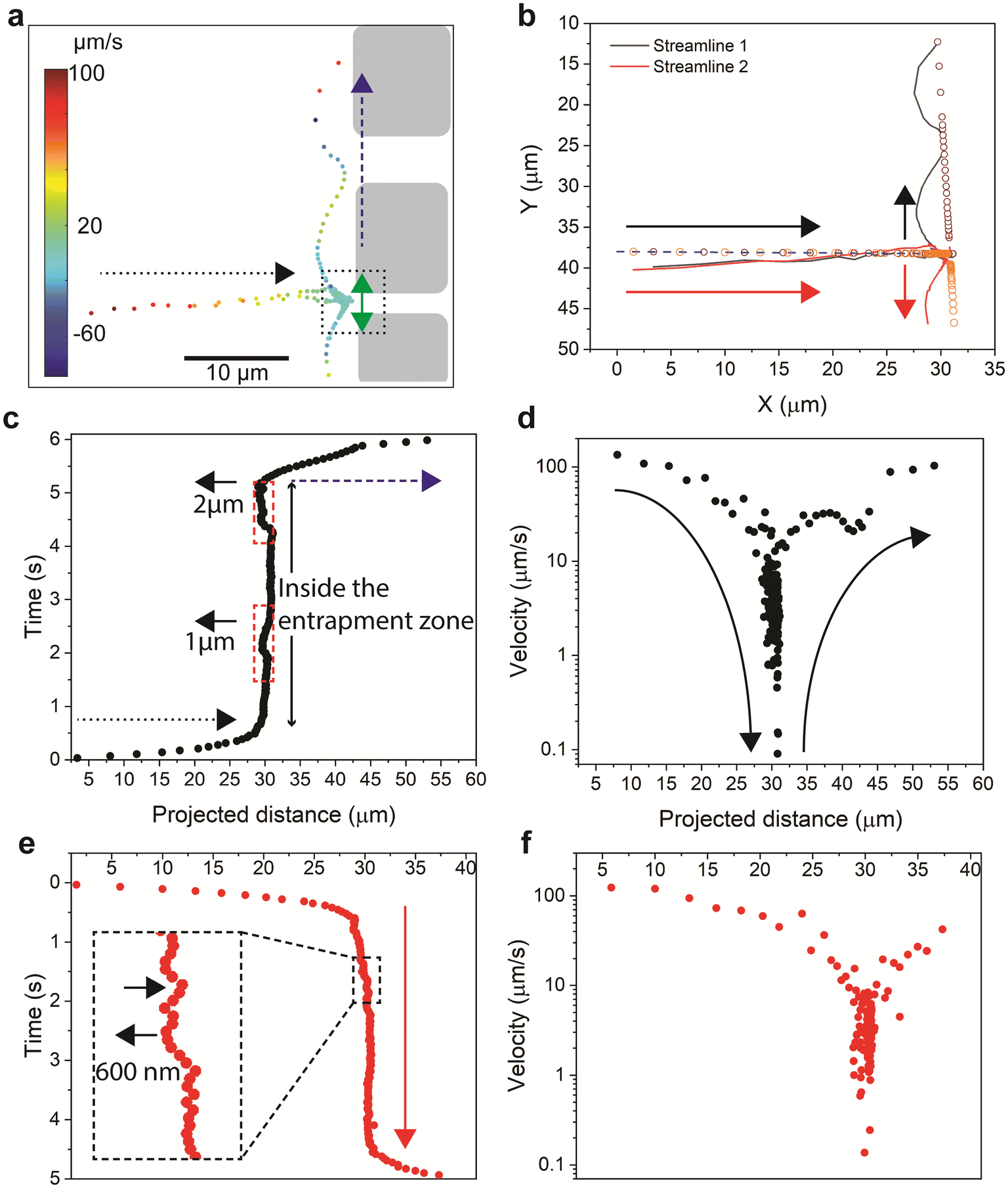 | ||
| Fig. 7 Quantitative analysis of the streamlines of two polymer agglomerates in a hydrodynamic entrapment zone. (a) Velocity map of the two streamlines. The dotted square illustrates the entrance of the 2 μm channel (see Fig. 5b). The dotted black arrow indicates the direction of streamlines toward the channels, whereas the blue dashed arrow indicates the direction of the streamlines parallel to the entrances of the channels. (b) Illustration of two streamlines of two flowing particles. The solid lines represent the actual path of flow, whereas the small circles represent the projected distance. The arrows represent the flow direction of the two particles. (c and d) The time (c) and velocity (d) along the path of streamline 1. The projected distance represents the summation of discrete displacements on both the horizontal and the vertical projection lines. The time variation over the path quantifies a residence time of 5 s. The dotted and dashed arrows are as described in (a). The short arrow indicates a backward motion of 1 μm and 2 μm, as indicated, of the entrapped particles. (e and f) The cumulative time (e) and velocity (f) along the path of streamline 1. The cumulative time variation over the path quantifies a residence time of 4 s. | ||
The time and the velocities along the path for the two polymer agglomerates are depicted in Fig. 7c–f. The polymer agglomerates' velocities reduce from values of 0.1 mm s−1 within the flow flux and during the flow towards the inlet of the channel, to values 3 orders of magnitude lower within the stagnant area. Furthermore, as the agglomerates are released from the stagnant zone to the flow flux, their velocity are restored to the values characteristic of the flow flux. Moreover, we observed that one agglomerate (Fig. 7c) showed two instances of backward movements (dotted red rectangles) with larger displacement values (1 μm and 2 μm), while the second agglomerate (Fig. 7e) had multiple forward-backward movements (black arrows) with smaller backward displacement (500–600 nm). Our results thus highlight a characteristic oscillating movement of the agglomerate in the entrapment zone, a behaviour that has not been theoretically predicted or experimentally elucidated before. During the oscillation movement, the agglomerates can generate localized flow patterns and introduce variations in the flow direction near the entrapment zone, affecting the local velocity gradients along the channel entrance. Studying such behavior can help gain insights into the complex behavior of polymer retention and transport in porous media, which can guide the development of more effective strategies for improving flow dynamics such as enhancing transport efficiency, in enhanced oil recovery, and in filtration processes.
To further characterize this behaviour we statistically analysed the polymer flow in 104 flow units. The hydrodynamic entrapment events were identified in 8 flow units (i.e., 7.7% occurrence rate). The analysis revealed interdependency between the probability of occurrence and the width of the channels as well as their clogging state (Fig. 8a). Our results show that the entrance of the 10 μm channels do not present favourable conditions for polymers to become hydrodynamically entrapped. In contrast, about half of the hydrodynamic events captured were associated with the 2 μm width channel, and the remaining events were associated with the two 5 μm channels of the flow units. To estimate the average hydrodynamic retention time of the flowing polymer particles, we auto-correlated temporal fluorescence intensity traces obtained at the entrance of the 2 μm and 5 μm channels (e.g., Fig. 5g). The obtained correlation time associated with hydrodynamic entrapments in our flow units ranged between 5.25 s and 12.25 s (Fig. 8b), with an average retention time of 9.2 s. The relatively short time scale of 9.2 s suggests that hydrodynamic retention may not induce a permanent alteration of the pore structure or a permeability reduction. This postulation agrees with experimental results from polymer floods conducted on reservoir rock samples.37,59,60 Nonetheless, this mechanism could retard polymer molecule transport compared to inert tracers, an observation that is well reported in the literature.61 For further details on the estimation and analysis of the average retention time, please refer to the ESI† Text III.
 | ||
| Fig. 8 Polymer retention in microchannels. (a) Frequency of hydrodynamic events related to channel width. (b) Frequency of calculated correlation time of temporal fluorescence intensity traces (see Fig. 5g). (c) Frequency of clogged channels related to channel width. (d) Frequency of flowing polymer agglomerates related to channel width. The red line is Gaussian fitting of the slow-flowing particles. | ||
Our analysis showed interdependency between polymer retention as a result of clogging (% of clogged channels) and the width of the channel (Fig. 8c). Interestingly, on average 25% of the 5 μm channels were clogged, whereas almost 90% of the 2 μm channels were clogged (Fig. 8c) as evidenced by the lack of polymer fluorescence (green color of the RGB scale, see Fig. 1h–j) in the channels (see the narrow channels in Fig. 5e and f). In addition, polymer agglomerates could not enter the 2 μm channels (Fig. 8d), as evidenced by the lack of red particles (highly fluorescent particles appearing as red particles, see Fig. 1h–j). Based on our observations, a channel width of 2 μm hinders the movement of polymer agglomerates. However, individual polymer molecules can still pass through the channel, although the fluorescence cannot be detected due to the channel's small volume. On the other hand, increasing the channel width to 5–10 μm enhances the flow of polymer molecules by 7.5 times. This finding underscores that polymer clogging is a complex process influenced by various factors, including the relative size of the polymer molecules to the channel width. Notably, the solution composition, including the polymer size distribution, remained consistent across all microfluidic units, ensuring a uniform distribution of polymer sizes for the channel-width statistics presented in Fig. 8a, c and d.
Conclusion
The proposed integrated approach of microfluidics and single-molecule fluorescence microscopy provided insights into fundamental mechanisms of fluid flow, where direct visualization has long-remained a gap in the field. Our microfluidic approach enabled enhanced throughput to investigate multiple flow mechanisms simultaneously. We provided the first direct visualization of three main mechanisms presumed to underlie polymer retention, which confirms their existence as proposed in the early 90s. The submicron resolution obtained enabled accurate single-particle tracking and molecular velocity determination, thus providing further evidence of the method's performance when applied to quantify the flow of complex fluids in porous media. We also provided essential insights about the motion of polymer particles in conduits undergoing clogging and unclogging and provided the first evidence of unclogging. However, further investigation is needed to explore the dynamics and mechanisms of unclogging in microfluidic systems, including developing theoretical models that incorporate the complex interplay of factors involved in polymer unclogging and validating these models through experimental studies. Our results resolve the controversial debate surrounding the existence of polymer retention reversibility and its implications for rock flow properties. However, further investigation is needed to explore the dynamics and mechanisms of unclogging in microfluidic systems, including developing theoretical models that incorporate the complex interplay of factors involved in polymer unclogging and validating these models through experimental studies.Considering the case analyzed in this paper, the polymer solution flow in porous geological media, the fundamental insights bring a key contribution to polymer-based enhanced oil recovery methods. Understanding polymer/rock interaction is crucial to the polymer screening stage and, thus, tackling the challenges that commonly jeopardize the success of the project. This work urges the need to develop more representative models for polymer retention and permeability reduction, which considers partial reversibility of these processes. Currently, none of the available models accounts for these mechanisms.
Our study highlights the future need for developing intricate microfluidic models to better understand the complex nature of flow mechanisms, their potential interrelation, and their implications in various applications. This advancement will provide crucial molecular insights and enhance our control over these processes in diverse fields.
Methods
Microfluidic device
The configuration of the microfluidic chips consists of two architectural identical structures that supply the inlet and outlet of the fluid and the flow structure (Fig. 1b). The flow structure holds multiple identical flowing units organized on five interconnected rows of forty units each. The array of flow units is designed to achieve several objectives: ensure repeatability of observations in different units, minimize the influence of boundary conditions, and prevent complete chip plugging.The microfluidic device was fabricated out of polydimethylsiloxane (PDMS) using a slightly tailored soft-lithography technique, at KAUST Nanofabrication Core Lab (Fig. 1b). An etched silicon wafer was used as a mold for the PDMS mixture, a key step to capture the different resolutions of the channels. The fabrication techniques enabled us to transfer the design through laser lithography to a chrome mask and subsequently through photolithography to a silicon wafer substrate. Deep reactive ion etching was used to permanently imprint the negative pattern of the pore-network, creating approximately 6 μm deep channels in the silicon wafer. The etched wafer served as a mold for the soft-photolithography technique, in which the microfluidic chip body was constructed out of PDMS, using a mixture of 10![[thin space (1/6-em)]](https://www.rsc.org/images/entities/char_2009.gif) :1 ratio of the polymeric base to the currying agent. The bonding of the PDMS part to a glass slide through oxygen plasma created the channels for fluid flow and the generically known “reservoir-on-a-chip”.
:1 ratio of the polymeric base to the currying agent. The bonding of the PDMS part to a glass slide through oxygen plasma created the channels for fluid flow and the generically known “reservoir-on-a-chip”.
Polymer solution
56 kDa poly(fluorescein isothiocyanate allylamine hydrochloride) was dissolved in distilled water at a concentration of 10 μg ml−1. The labeled polymer was excited at 488 nm, and emission was detected through a 540 ± 40 nm bandpass filter. The specifications of wide-field microscopy are described in the following section.Flow experiments operating conditions
Single-phase polymer flooding experiments were conducted on the designed chips to study polymer transport behavior in porous media. The ports of the microfluidic chip were plumbed with blunt needle tips connected through polyethylene tubing at the inlet of the fluid holding vial open to the atmosphere, and at the outlet to a Harvard syringe pump. The microfluidic chip was initially saturated with the polymer solution by creating negative pressure in the system using a 10 μl min−1 preset flow rate. After saturation, the pump was shut off, and fluids flowed into the system at microscopic flow rates.Single-molecule fluorescence imaging setup
The single-molecule fluorescence imaging experiments were conducted on a custom-built epifluorescence inverted microscope (IX71, Olympus, Tokyo, Japan) illuminated with a CW 60 mW 488 nm laser (MLD, Cobolt).66–68 The laser line was reflected to an Olympus UPLANFL N 20× NA0.5 objective lens by an FF506-Di03 25 × 36 dichroic mirror (Semrock). The output of the excitation laser was synchronized to an iXon Ultra EMCCD camera (Andor Technology, Belfast, Ireland) to illuminate the sample. The fluorescence from single molecules was collected by the same objective lens and then passed through an FF01-540/50-25 emission filter (Semrock).Single-molecule fluorescence images
Fluorescence images were acquired using the Andor iQ imaging software, at 35 ms sampling time with a pixel size of 500 nm, with 1000 frames (512 × 512 pixels) acquired in each stack of frames. The raw images were post-processed using the image analysis software, ImageJ. The acquired greyscale images were converted to RGB scale for enhanced visualization purposes. The RGB scale emphasizes different fluorescence intensity levels, where blue represents low intensity or no polymeric material, and green and red correspond to moderate- and high-intensity levels, respectively. This color scale indicates the presence of polymer molecules in green and polymer agglomerations in red. To calculate the normalized mean pixel intensity (NPI of intensity fluctuations after desorption) we subtracted 0.5 × standard deviation from the mean of the NPI to decrease the impact of background noise.Atomic force microscopy and dynamic light scattering
AFM measurements were done using a Bruker Dimension Icon AFM in intermittent contact mode with a FESPA-V2 probe (Bruker). The data analyses were done by using Gwyddion software.69 The hydrodynamic size of polymer molecules in solution was determined using the dynamic light scattering method. The measurements were conducted on a Zetasizer Nano-ZS instrument by Malvern.Particle tracking velocimetry (PTV)
The TrackMate functionality in Fiji-ImageJ was used to process the acquired images and by applying single-particle tracking analysis. Each individual polymer agglomerate was segmented in multiple frames, and the tracks were reconstructed by assigning it an identity over the frames.70 The analysis resulted in determining the streamlines of polymer agglomerates and the transport velocity along the streamlines. PTV was performed on the polymer agglomerates as low density of the tracked particles is necessary to ensure accurate particle identification and spatial determination for one-to-one tracking.71Author contributions
Antonia Sugar: did the chip fabrication and prepared the original draft of the manuscript. Antonia Sugar and Maged Serag: did the imaging experiments and analyzed the data. Maged Serag: wrote the manuscript. Urlich Buttner: guided the fabrication. Satoshi Habuchi: supervised the project and wrote the manuscript. Hussein Hoteit: conceptualized the work, supervised and validated the methodology, and reviewed and edited the paper.Conflicts of interest
There are no conflicts to declare.Acknowledgements
The authors would like to express gratitude to King Abdullah University of Science & Technology for funding and supporting this work.References
- R. G. Larson, The Structure and Rheology of Complex Fluids, Oxford University Press, New York, 1999 Search PubMed.
- M. Kröger and J. Vermant, The structure and rheology of complex fluids, Appl. Rheol., 2000, 10, 110–111 Search PubMed.
- L. W. Lake, Enhanced oil recovery, Prentice-Hall Inc., Englewood Cliffs, 1989 Search PubMed.
- J. A. K. Silva, J. E. Mccray, M. Liberatore and M. Asce, Characterization of bulk fluid and tansport properties for simulating polymer-improved aquifer remediation, J. Environ. Eng., 2013, 139, 149–159 CrossRef CAS.
- T. Bultreys, W. De Boever and V. Cnudde, Imaging and image-based fluid transport modeling at the pore scale in geological materials: A practical introduction to the current state-of-the-art, Earth-Sci. Rev., 2016, 155, 93–128 CrossRef.
- E. C. Kumbur, K. V. Sharp and M. M. Mench, Liquid droplet behavior and instability in a polymer electrolyte fuel cell flow channel, J. Power Sources, 2006, 161, 333–345 CrossRef CAS.
- E. Kjeang, et al., Microfluidic Fuel Cell with Flow-Through Porous Electrodes, J. Am. Chem. Soc., 2008, 130, 4000–4006 CrossRef CAS PubMed.
- A. Anbari, et al., Microfluidic model porous media: Fabrication and applications, Small, 2018, 14, 1703575 CrossRef PubMed.
- V. Berejnov, N. Djilali and D. Sinton, Lab-on-chip methodologies for the study of transport in porous media: Energy applications, Lab Chip, 2008, 8, 689–693 RSC.
- F. J. Galindo-Rosales, Complex fluid-flows in microfluidics, Springer International Publishing, 2017 Search PubMed.
- J. Wu, G. Zheng and L. M. Lee, Optical imaging techniques in microfluidics and their applications, Lab Chip, 2012, 12, 3566–3575 RSC.
- P. Mirbod, Z. Wu and G. Ahmadi, Laminar flow drag reduction on soft porous media, Sci. Rep., 2017, 7, 17263 CrossRef PubMed.
- D. F. do Nascimento, et al., Pore scale visualization of drainage in 3D porous media by confocal microscopy, Sci. Rep., 2019, 9, 12333 CrossRef PubMed.
- I. Zarikos, et al., Velocity distributions in trapped and mobilized non-wetting phase ganglia in porous media, Sci. Rep., 2018, 8, 13228 CrossRef CAS PubMed.
- H. Amini, et al., Engineering fluid flow using sequenced microstructures, Nat. Commun., 2016, 4, 1826 CrossRef PubMed.
- D. Kawale, J. Jayaraman and P. E. Boukany, Microfluidic rectifier for polymer solutions flowing through porous media, Biomicrofluidics, 2019, 13, 014111 CrossRef PubMed.
- D. Kawale, et al., Polymer conformation during flow in porous media, Soft Matter, 2017, 13, 8745–8755 RSC.
- W. E. Moerner and D. P. Fromm, Methods of single-molecule fluorescence spectroscopy and microscopy, Rev. Sci. Instrum., 2003, 74, 3597–3619 CrossRef CAS.
- S. Shashkova and M. C. Leake, Single-molecule fluorescence microscopy review: Shedding new light on old problems, Biosci. Rep., 2017, 37, BSR20170031 CrossRef CAS PubMed.
- G. U. Nienhaus and K. Nienhaus, Fluorescence Labeling, in Fluorescence Microscopy, John Wiley & Sons, Ltd., 2013 Search PubMed.
- H. Yokota, Fluorescence microscopy for visualizing single-molecule protein dynamics, Biochim. Biophys. Acta, Gen. Subj., 2020, 1864, 129362 CrossRef CAS PubMed.
- L. Lake, R. Johns, W. Rossen and G. Pope, Fundamentals of Enhanced Oil Recovery, Society of Petroleum Engineers, 2014, DOI:10.2118/9781613993286.
- W. Littmann, Polymer flooding, Elsevier Science Pub. Co., 1988 Search PubMed.
- F. W. Smith, The Behavior of Partially Hydrolyzed Polyacrylamide Solutions in Porous Media, J. Pet. Technol., 1970, 22, 148–156 CrossRef.
- M. T. Szabo, Laboratory Investigations of Factors Influencing Polymer Flood Performance, Soc. Pet. Eng. J., 1975, 15, 338–346 CrossRef CAS.
- P. G. De Gennes, Dynamics of Entangled Polymer Solutions. I. The Rouse Model, Macromolecules, 1976, 9, 587–593 CrossRef CAS.
- N. Mungan, Rheology and Adsorption of Aqueous Polymer Solutions, J. Can. Pet. Technol., 1969, 8, 45–50 CrossRef CAS.
- J.-J. Lee and G. Fuller, Adorption and desorption of flexible pollymer chains in flowing systems, J. Colloid Interface Sci., 1985, 103, 569–577 CrossRef CAS.
- V. A. Torrealba and H. Hoteit, Improved polymer flooding injectivity and displacement by considering compositionally-tuned slugs, J. Pet. Sci. Eng., 2019, 178, 14–26 CrossRef CAS.
- R. Santoso, V. Torrealba and H. Hoteit, Investigation of an Improved Polymer Flooding Scheme by Compositionally-Tuned Slugs, Process, 2020, 8, 197 CrossRef CAS.
- K. S. Sorbie, Polymer-Improved Oil Recovery, Springer, Netherlands, 1991, DOI:10.1007/978-94-011-3044-8.
- G. J. Hirasaki and G. A. Pope, Analysis of Factors Influencing Mobility and Adsorption in the Flow of Polymer Solution Through Porous Media, Soc. Pet. Eng. AIME J., 1974, 14, 337–346 CrossRef CAS.
- J. Klein and W. M. Kulicke, Polymer-polymer and polymer-solid interaction and their relevance for polymer application in enhanced oil recovery, in SPE Oilfiled and Geothermal Chemistry Symposium, Standord, California, 1980 Search PubMed.
- Y. Cohen and F. R. Christ, Polymer retention and adsorption in the flow of polymer solutions through porous media, SPE Reserv. Eng., 1986, 1, 113–118 CrossRef CAS.
- W. B. Gogarty, Mobility Control With Polymer Solutions, Soc. Pet. Eng. J., 1967, 7, 161–173 CrossRef CAS.
- M. Szabo, Some Aspects of Polymer Retention in Porous Media Using a C14 Tagged Polyacrylamide. Polyelectrolytes and their Applications, Soc. Pet. Eng. J., 1975, 15, 323–337 CrossRef CAS.
- J. G. Dominguez and G. P. Willhite, Retention and flow characteristics of polymer solutions in porous media, Soc. Pet. Eng. AIME J., 1977, 17, 111–121 CrossRef CAS.
- G. Chauveteau and N. Kohler, Polymer Flooding: The Essential Elements for Laboratory Evaluation, in SPE Improved Oil Recovery Symposium, Society of Petroleum Engineers, 1974, DOI:10.2118/4745-MS.
- Z. Chen, et al., A study of factors influencing polymer hydrodynamic retention in porous media, in SPE - DOE Improved Oil Recovery Symposium Proceedings, Society of Petroleum Engineers, 2016, vol. 2016 Search PubMed.
- G. Zhang and R. S. Seright, Hydrodynamic Retention and Rheology of EOR Polymers in Porous Media, in SPE International symposium on oilfiled chemistry, Texas, USA, 2015 Search PubMed.
- S. Al-Hajri, S. M. Mahmood, H. Abdulelah and S. Akbari, An overview on polymer retention in Porous media, Energies, 2018, 11, 2751 CrossRef.
- S. Gogoi and S. B. Gogoi, Review on microfluidic studies for EOR application, J. Pet. Explor. Prod. Technol., 2019, 9, 2263–2277 CrossRef.
- Z. Wang and D. Voicu, et al., Microfluidic studies of polymer adsorption in flow, Lab Chip, 2015, 15, 2110–2116 RSC.
- M. Buchgraber, et al., A microvisual study of the displacement of viscous oil by polymer solutions, SPE Reservoir Eval. Eng., 2011, 14, 269–280 CrossRef CAS.
- W. Lei, et al., Enhanced oil recovery mechanism and recovery performance of micro-gel particle suspensions by microfluidic experiments, Energy Sci. Eng., 2019, 8, 986–998 CrossRef.
- M. Lacey, C. Hollis, M. Oostrom and N. Shokri, Effects of Pore and Grain Size on Water and Polymer Flooding in Micromodels, Energy Fuels, 2017, 31, 9026–9034 CrossRef CAS.
- H. E. Al-Sharji, C. A. Grattoni, R. A. Dawe and R. W. Zimmerman, Disproportionate Permeability Reduction Due to Polymer Adsorption Entanglement, SPE European Formation Damage Conference, SPE-68972-MS, 2001, DOI:10.2118/68972-MS.
- H. Ghahremani, S. Mobaraki, S. S. Khalilinezhad and K. Jarrahian, An experimental study of the performance of low-molecular weight polymer for enhanced heavy oil recovery in a heterogeneous media, Geosyst. Eng., 2018, 21, 95–102 CrossRef CAS.
- C. A. Browne, A. Shih and S. S. Datta, Pore-Scale Flow Characterization of Polymer Solutions in Microfluidic Porous Media, Small, 2020, 16, 1903944 CrossRef CAS PubMed.
- P. Gramain and P. Myard, Adsorption studies of polyacrylamides in porous media, J. Colloid Interface Sci., 1981, 84, 114–126 CrossRef CAS.
- I. Lakatos, J. Lakatos-Szabó and J. Tóth, Factors Influencing Polyacrylamide Adsorption in Porous Media and Their Effect on Flow Behavior, in Surface Phenomena in Enhanced Oil Recovery, ed. D. O. Shah, Springer, US, 1981, DOI:10.1007/978-1-4757-0337-5_37.
- Y. Huang and K. S. Sorbie, Scleroglucan Behavior in Flow Through Porous Media: Comparison of Adsorption and In-Situ Rheology With Xanthan, in SPE International Symposium on Oilfield Chemistry, Society of Petroleum Engineers, 1993, DOI:10.2118/25173-MS.
- D. Broseta, F. Medjahed, J. Lecourtier and M. Robin, Polymer Adsorption/Retention in Porous Media: Effects of Core Wettability and Residual Oil, SPE Adv. Technol. Ser., 1995, 3, 103–112 CrossRef.
- K. Denys, C. Fichen and A. Zaitoun, Bridging Adsorption Of Cationic Polyacrylamides In Porous Media, in SPE International Symposium on Oilfield Chemistry, Society of Petroleum Engineers, 2001, DOI:10.2118/64984-MS.
- V. H. S. Ferreira and R. B. Z. L. Moreno, Polyacrylamide Adsorption and Readsorption in Sandstone Porous Media, SPE J., 2019, 25, 497–514, DOI:10.2118/199352-PA.
- G. Cheraghian, S. S. Khalili Nezhad, M. Kamari, M. Hemmati, M. Masihi and S. Bazgir, Adsorption polymer on reservoir rock and role of the nanoparticles, clay and SiO2, Int. Nano Lett., 2014, 4, 114 CrossRef.
- W. Yun and A. R. Kovscek, Microvisual investigation of polymer retention on the homogeneous pore network of a micromodel, J. Pet. Sci. Eng., 2015, 128, 115–127 CrossRef CAS.
- J. Zhao, H. Fan, Q. You and Y. Jia, Distribution and presence of polymers in porous media, Energies, 2017, 10, 2118 CrossRef.
- J. M. Marker, Dependence of Polymer Retention on Flow Rate, J. Pet. Technol., 1973, 25, 1307–1308 CrossRef.
- G. Zhang and R. S. Seright, Hydrodynamic retention and rheology of EOR polymers in porous media, in Proceedings - SPE International Symposium on Oilfield Chemistry, Society of Petroleum Engineers (SPE), 2015, vol. 1 Search PubMed.
- D. S. Hughes, D. Teeuw, C. W. Cottrell and J. M. Tollas, Appraisal of the use of polymer injection to suppress aquifer influx and to improve volumetric sweep in a viscous oil reservoir, SPE Reserv. Eng., 1990, 5, 33–40 CrossRef CAS.
- M. V. D'Angelo, R. Chertcoff and M. Rosen, Trapping phenomena in a flow of polymer solution, Heat Technol., 2003, 21, 73–76 Search PubMed.
- S. Al-Hajri, et al., An Experimental Study on Hydrodynamic Retention of Low and High Molecular Weight Sulfonated Polyacrylamide Polymer, Polymers, 2019, 11, 1453 CrossRef CAS PubMed.
- G. Chauveteau, K. Denys and A. Zaitoun, New Insight on Polymer Adsorption Under High Flow Rates, in SPE/DOE Improved Oil Recovery Symposium, Society of Petroleum Engineers, 2002, DOI:10.2118/75183-MS.
- A. S. Gundogar, C. M. Ross, S. Akin and A. R. Kovscek, Multiscale pore structure characterization of middle east carbonates, J. Pet. Sci. Eng., 2016, 146, 570–583 CrossRef CAS.
- M. F. Serag, M. Abadi and S. Habuchi, Single-molecule diffusion and conformational dynamics by spatial integration of temporal fluctuations, Nat. Commun., 2014, 5, 5123 CrossRef CAS PubMed.
- M. Abadi, M. F. Serag and S. Habuchi, Entangled polymer dynamics beyond reptation, Nat. Commun., 2018, 9, 5098 CrossRef PubMed.
- K. Abuzineh, et al., Microfluidics-based super-resolution microscopy enables nanoscopic characterization of blood stem cell rolling, Sci. Adv., 2018, 4, eaat5304 CrossRef CAS PubMed.
- D. Nečas and P. Klapetek, Gwyddion: an open-source software for SPM data analysis, Cent. Eur. J. Phys., 2012, 10, 181–188 Search PubMed.
- J. Y. Tinevez, et al., TrackMate: An open and extensible platform for single-particle tracking, Methods, 2017, 115, 80–90 CrossRef CAS PubMed.
- T. Dracos, Particle Tracking Velocimetry (PTV), in Three-Dimensional Velocity and Vorticity Measuring and Image Analysis Techniques, ed. T. Dracos, Springer, Netherlands, 1996, pp. 155–160, DOI:10.1007/978-94-015-8727-3_7.
Footnotes |
| † Electronic supplementary information (ESI) available. See DOI: https://doi.org/10.1039/d3lc00467h |
| ‡ SLB, Itd. Bucharest, Romania. |
| This journal is © The Royal Society of Chemistry 2023 |