
 Open Access Article
 This Open Access Article is licensed under a
 Creative Commons Attribution 3.0 Unported Licence
Magnetically controlled flexible micro-robots based on magnetic particle arrangement†
Zhifa
Tang
a,
Zhiqiang
Xu
 *ab,
Xinqian
Bo
a,
Feng
Chen
a,
Heng
Wu
c,
Zhixiong
Li
a and
Shengqiang
Jiang
ab
*ab,
Xinqian
Bo
a,
Feng
Chen
a,
Heng
Wu
c,
Zhixiong
Li
a and
Shengqiang
Jiang
ab
aSchool of Mechanical Engineering, Xiangtan University, Xiangtan, China. E-mail: xzq2018@xtu.edu.cn
bEngineering Research Center of Complex Tracks Processing Technology and Equipment of Ministry of Education, Xiangtan University, Xiangtan, China
cNational Engineering Research Center of Novel Equipment for Polymer Processing, South China University of Technology, Guangzhou 510641, China
First published on 16th January 2023
Abstract
Magnetically controlled flexible micro-robots can assume desired shapes and motions driven by external magnetic fields, which makes them promising for applications in healthcare and robotics. However, current magnetically controlled flexible micro-robot design methods suffer from size constraints and high manufacturing costs. Here, we report on a composite material based on programmed magnetic powder arrangements that can produce fast, reversible, and programmable shape transformations under magnetic fields. In addition, we investigate this composite's magnetically controlled deformation mechanism through experiments and numerical simulations. With these excellent properties, the composite can be used to design magnetically controlled flexible micro-robots with swimming, transport, and clamping functions.
1. Introduction
With the booming development of micro-nano manufacturing technology, drive technology has also ushered in significant innovations, among which micro-robots have received a lot of attention for their unique advantages.1 Micro-robots refer to controllable devices with dimensions from micrometer to millimeter,2 and due to their small size, these micro-robots can access complex and narrow areas in the human body in a minimally invasive manner, such as the gastrointestinal tract, the vascular system, the brain, and the eyes.3 At the same time, they possess higher degrees of freedom, flexibility and adaptability compared to conventional large robots.4,5 In addition, the micro-robots have multiple drive modes such as electric field drive,6,7 chemical drive,8–11 thermal drive,12,13 light drive,14–16 pressure drive,4,17 or magnetic field drive.18–23 In particular, magnetic fields can easily and harmlessly penetrate most biological and synthetic materials and provide a safe and effective actuation method, which endows magnetically controlled flexible micro-robots with great prospects for applications in healthcare and robotics.24–26Magnetically controlled flexible micro-robots can be pre-programmed to design movement patterns that allow them to perform a variety of small operational tasks in highly complex and restricted space.27,28 Programming design here refers to the method of patterning magnetic particles in polymer composites, where the magnetic particles can be soft magnetic29 or hard magnetic.30 Here, the patterning method of soft magnetic particles is performed by designing the magnetic axis,31 while the patterning method of hard magnetic particles is performed by pre-magnetization.30 In contrast, the residual magnetization method for hard magnetic particles allows the design of more complex functions such as complex motion patterns31,32 and fast 3D shape transformations.30 However, hard magnetic particles can only be synthesized in sizes of microns or larger, and the hard magnetic particles have a large hysteresis loop, which means that the driving magnetic field strength and magnetization strength have significant non-linearity. Also, the interaction of magnetized particles in the polymer matrix can easily cause rotation and motion of the magnetized particles, which leads to changes in magnetic domains.33 As a result, magnetically controlled mechanical properties based on hard magnetic domains exhibit hysteresis and nonlinear behavior.34,35
As shown in Table 1, photo-lithographic molding is currently an effective method for manufacturing shape programmable magnetic micro-robots.13,36,37 Kim et al.37 first immersed soft magnetic particles into a light-cured polymer solution, applied an external magnetic field to assemble soft magnetic particles into magnetic axes, and used ultraviolet (UV) light to irradiate selected regions in the solution to induce their polymerization. In 2019, Xu et al.36 immersed hard magnetic particles into a light-cured polymer solution for the first time. This method can precisely adjust the magnetization direction of the hard magnetic particles by an external strong magnetic field to achieve a programmable morphology of magnetically controlled flexible microrobots.
Although the lithographic patterning method for hard magnetic particles offers great flexibility in building shape programmable magnetic microrobots, the presence of a maximum nanoparticle density limit for hard magnetic particles in the lithographic patterning method limits the maximum volume of the magnetic material for such magnetic robots.38 In addition, similar to the photolithographic patterning method for soft magnetic particles, the use of photocuring equipment is required. Therefore, the existing fabrication methods suffer from size limitation and high cost.
In this paper, we report on a composite material based on a programmed magnetic powder arrangement that can produce fast, reversible, and programmable shape transitions under magnetic fields. In addition, we investigate the magnetically controlled deformation mechanism of this composite material through experiments and numerical simulations and design magnetically controlled flexible micro-robots with swimming, transport, and gripping functions based on this composite material. Compared with the photolithographic patterning method, the magnetic micro-robots prepared by this method are smaller in size. Also, the polymer matrix is naturally cured and uses a very small amount of soft magnetic particles, eliminating the need for repetitive preparation of the magnetic shaft. This greatly reduces the manufacturing conditions and manufacturing costs. As a result, this research in this paper provides a new method for the preparation of magnetically controlled flexible robots.
2. Experimental
2.1. Materials and methods
The polymer matrix used in this paper is a silicone rubber material, which is provided by Shenzhen Hongyejie Technology Co. The silicone rubber solution consists of part A and part B. Curing occurs after mixing in a 1![[thin space (1/6-em)]](https://www.rsc.org/images/entities/char_2009.gif) :1 mass ratio. The soft magnetic particles are spherical iron powder provided by Xindun Alloy Co. The specific parameters of the material are shown in Table 2.
:1 mass ratio. The soft magnetic particles are spherical iron powder provided by Xindun Alloy Co. The specific parameters of the material are shown in Table 2.
| Parameters | Value (Unit) |
|---|---|
| Iron particle density (ρp) | 7.870 (g cm−3) |
| Iron particle radius (μm) | 180 (μm) |
| Silicone rubber density (ηf) | 1.03 (g cm−3) |
| Silicone rubber magnetic permeability (μf) | 1 |
As shown in Fig. 1(a), the silicone rubber solution Part A and Part B were mixed in a 1:1 mass ratio and injected into a flat mold. As shown in Fig. 1(c), the magnetic particles were arranged into a pre-designed structure using an electromagnetic needle under a microscope. Here the electromagnetic needle works as shown in Fig. 1(b). The tip of the electromagnetic needle generates a switch-dependent gradient magnetic field, which allows controlled adsorption of soft magnetic particles. At the same time, the magnetic field generated by the electromagnetic needle is very small, avoiding interference with the already aligned magnetic powder during the alignment process. As shown in Fig. 1(d), the cured silicone rubber was demolded. As shown in Fig. 1(e), the demolded silicone rubber was cut under the microscope and the soft magnetic particle fraction was extracted.
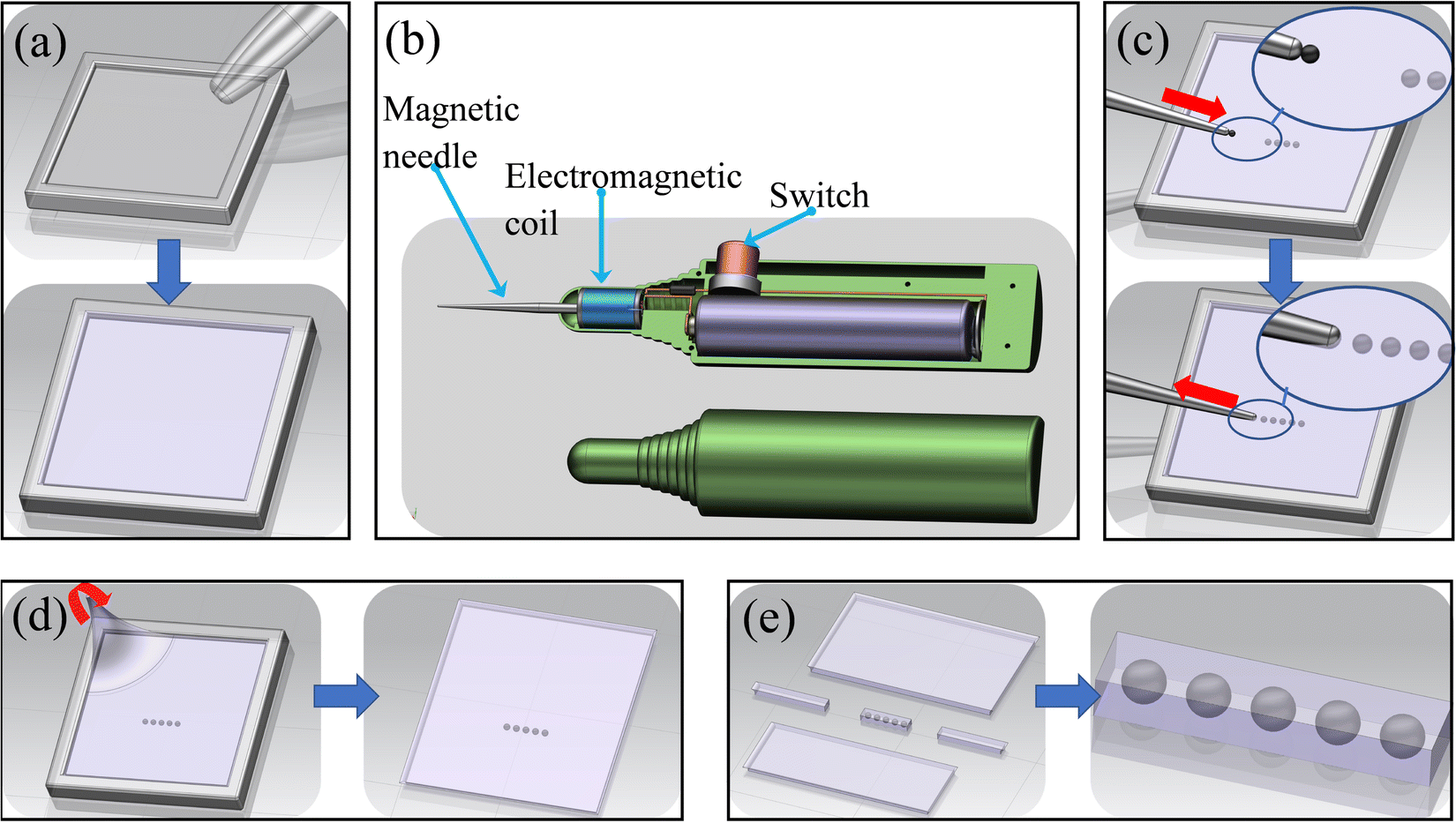 | ||
| Fig. 1 Fabrication process of magnetically controlled flexible micro-robot based on magnetic powder arrangement. (a) Injection of silicone rubber solution into the mold. (b) Schematic diagram of the operation of the electromagnetic needle. (c) Preset structural arrangement of soft magnetic particles. (d) Demolding of the cured silicone rubber. (e) Cutting of silicone rubber. | ||
2.2. Numerical models
In this section, we will study the deformation-related behavior of the above composite material by establishing a mathematical model, whose deformation mechanism is shown in Fig. 2, where H0 indicates the applied uniform magnetic field, the black arrow indicates the magnetic force on the surface of the magnetic particle, and the red arrow indicates the stress acting on the surface of the magnetic particle by the polymer matrix, and the magnitude of the force is indicated by the length of the arrow.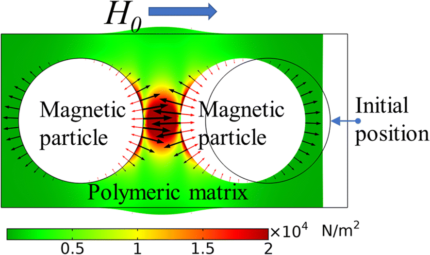 | ||
| Fig. 2 Magnetically controlled deformation model. | ||
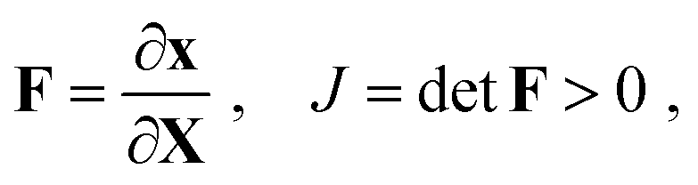
Currently, the theory of magnetoelastic continuum in magnetic elastomer composites has been intensively investigated by Danas et al.,39 Dorfmann and Ogden,40 and Kankanala and Triantafylidis.41 Therefore, the purpose of this section is not to redevelop the theory, but to apply it to the study of the deformation-related behavior of the above composite material. Here, the silicone rubber matrix and the soft magnetic particles are considered as a continuum with different material properties. According to the basic knowledge of continuum media mechanics, the deformation gradient F and its determinant J are defined as:
 | (1) |
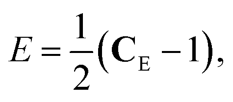
Based on the reference configuration (Lagrangian description), the strain measurement in terms of material coordinates is defined using the symmetric right Cauchy Green tensor CE, i.e.:
| CE = FTF, | (2) |
From this, the strain E can be calculated by the following equation:
 | (3) |
As shown in Fig. 2, the deformation of the composite material is caused by the magnetic interaction between magnetic particles, and here the electromagnetic analysis problem is a problem of solving a set of Maxwell's equations under a given set of boundary conditions, where the magnetic field is controlled by the static Maxwell's equations in the absence of free current. Thus, the equations can be written as:
| ∇ × H = 0 | (4) |
| ∇ × B = 0 | (5) |
| B = μH | (6) |
On the boundary surface, the boundary conditions of B and H are shown as follows:
| n·(B+ − B−) = 0, n × (H+ − BH) = 0 | (7) |
The Maxwell stress tensor τm acting on a soft magnetic particle is expressed as:
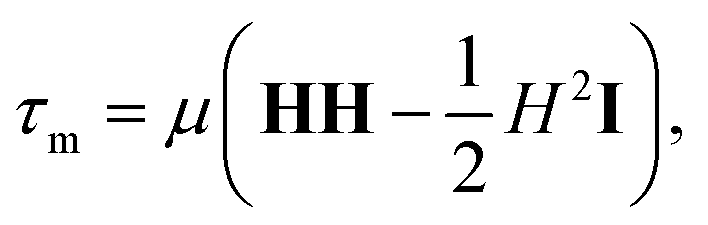 | (8) |
 | (9) |
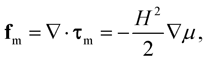
As shown in Fig. 2, the magnetic force fm on the surface of the soft magnetic particle is balanced with the stresses acting on the surface of the soft magnetic particle by the polymer matrix. Thus, the magnetic and elastic behaviors can be coupled by incorporating fm into the force equilibrium equation. Also in the stationary case, the equilibrium equation is shown below according to the basic equilibrium principle of continuum media mechanics:
| ∇·τ + ρf + fm = 0, | (10) |
2.3. Material characterization
Fig. 3(a) shows a plot of the experimental sample for the uniaxial tensile test of the polymer matrix. The obtained stress–strain relationship plot for this experimental sample is shown in Fig. 3(b) Since the stress–strain curve in the plot tends to be straight and the strain of the polymer matrix in this experiment is less than 100%, we assume that the simulated polymer matrix follows the binomial parameter Mooney–Rivlin free energy density function W, as follows.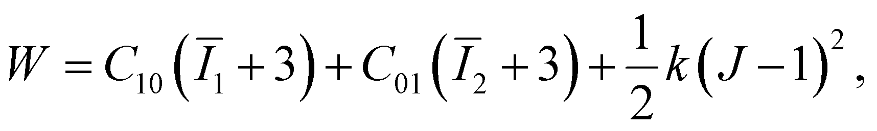 | (11) |
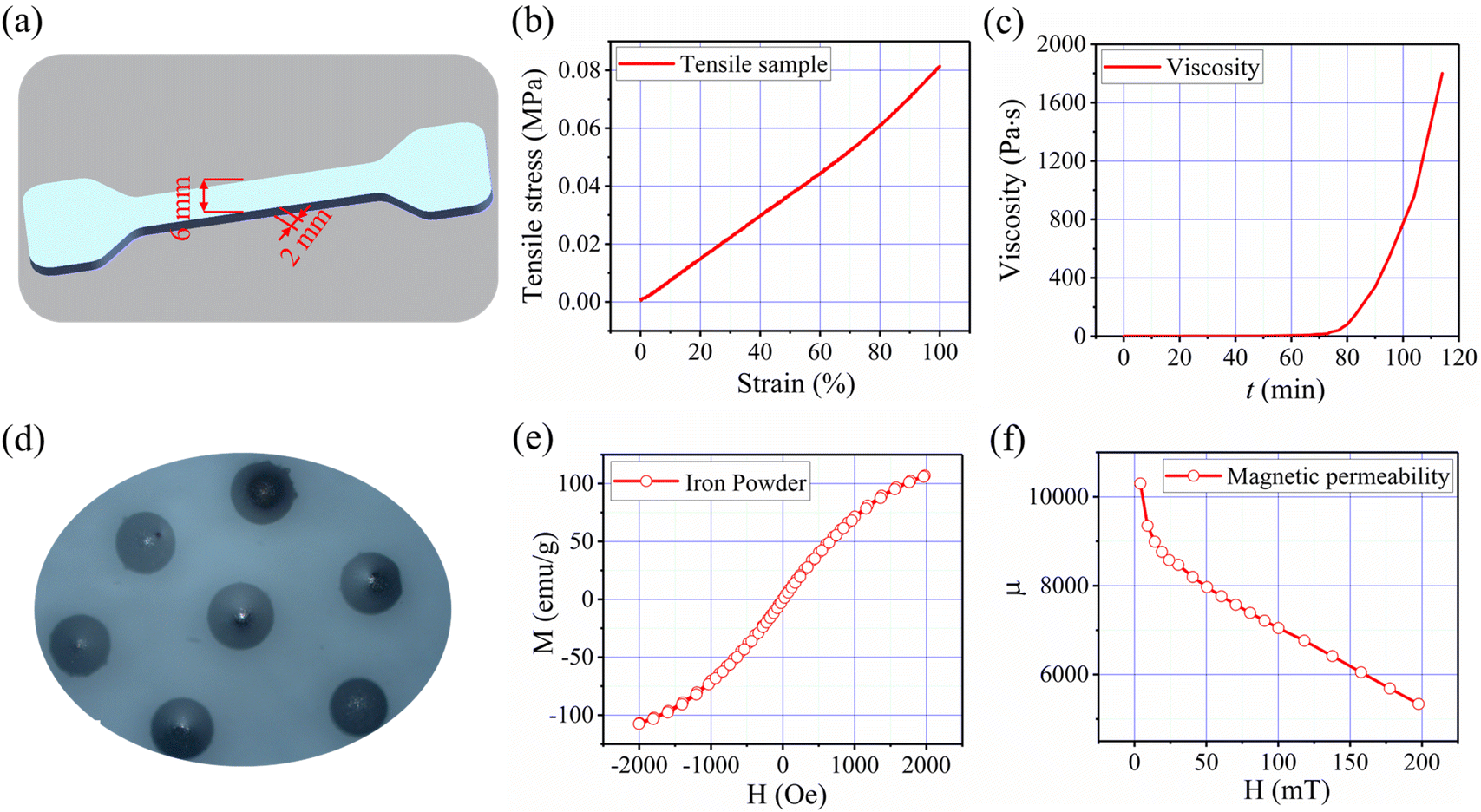 | ||
| Fig. 3 Material characterization. (a) Uniaxial tensile experimental sample of the silicone rubber substrate. (b) Stress–strain curve of silicone rubber, (c) viscosity/time curve of silicone rubber, (d) experimental sample of iron particles, (e) magnetic hysteresis loop of iron particles, and (f) magnetic permeability curve of iron particles. | ||
As shown in Fig. 3(c), the viscosity profile of the silicone rubber matrix during curing was measured in a thermostat, which indicates that the silicone rubber matrix was fully cured after two hours and therefore by enough time to align the soft magnetic particles.
2.4. Numerical model establishment and validation
Based on the deformation theory in Section 3.2 and the material characterization in Section 3.3, a 3D numerical model was developed using COMSOL Multiphysics finite element software and experimentally verified. As shown in Fig. 4(a), the geometry of the experimental sample was photographed under a microscope to obtain Fig. 4(b). As shown in Fig. 4(c), the corresponding geometric model is created from the geometric model of the sample under test in the geometry command bar of COMSOL Multiphysics finite element simulation software. The values of the material parameters measured in Fig. 3 in the Material command field are entered and the solid mechanics module (solid) and the magnetostatics module (mfnc) are added ain the next step. Here the solid mechanics module is used to calculate eqn (1)–(3) and (10), (11), while the magnetostatics module is used to solve eqn (4)–(9). After establishing the numerical model, the geometric model meshes are established.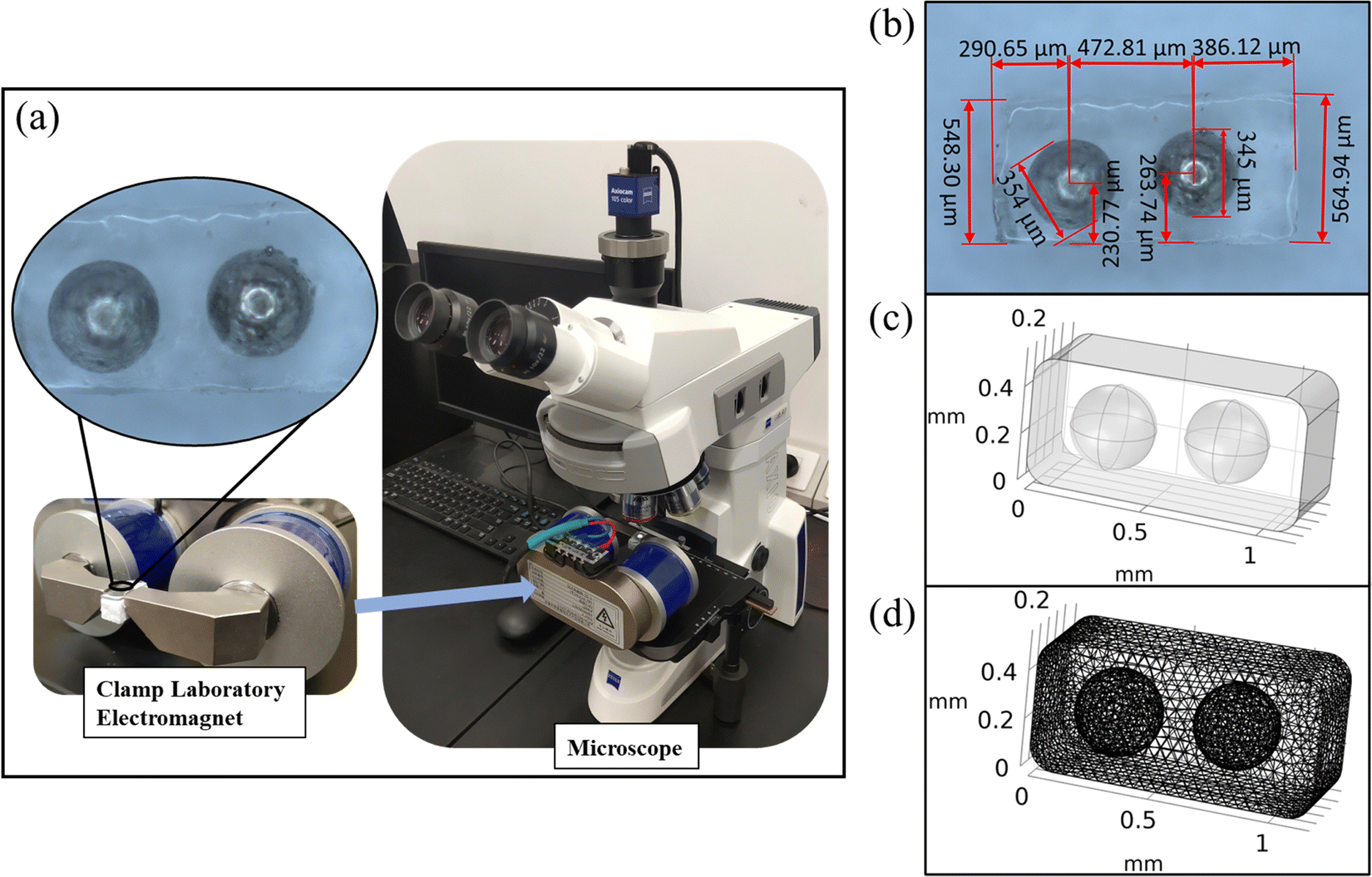 | ||
| Fig. 4 Numerical modeling, (a) the sample geometry measurement method. (b) The geometry of the sample. (c) Geometric model building. (d) Geometric model meshing. | ||
As shown in Fig. 5, the experiments and numerical simulations were compared to verify the accuracy of the numerical simulations. Here, the uniform magnetic field in the experiment is provided by the clamp electromagnet in Fig. 4(a), and the deformation is photographed using a microscope.
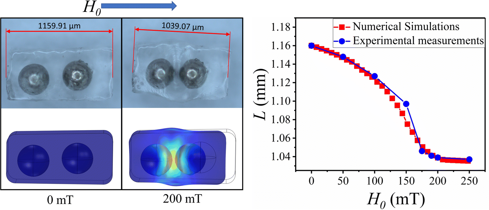 | ||
| Fig. 5 Numerical simulation results and simulation validation. | ||
The results in Fig. 5 show that the numerical simulation results agree with the experimental results.
3. Results and discussion
3.1. Magnetically controlled deformation
In this section, several basic deformation capabilities of composite materials are investigated, as well as the effect of the arrangement of magnetic particles on deformation.As shown in Fig. 6, the magnetic particles were arranged in parallel within the polymer matrix and when a magnetic field parallel to the direction of magnetic particle arrangement was applied, the magnetic particles were magnetized and attracted to each other, which resulted in the compression of the polymer matrix. Fig. 6(a) shows the amount of compression of the polymer matrix versus the strength of a uniform magnetic field. Fig. 6(b) shows the relationship between the spacing of the magnetic particle arrangement and the amount of compression of the polymer matrix. In addition, the compression deformation of the polymer matrix was visualized using the numerical simulation method in Section 3.4, and the simulation results are shown in Fig. 6(c).
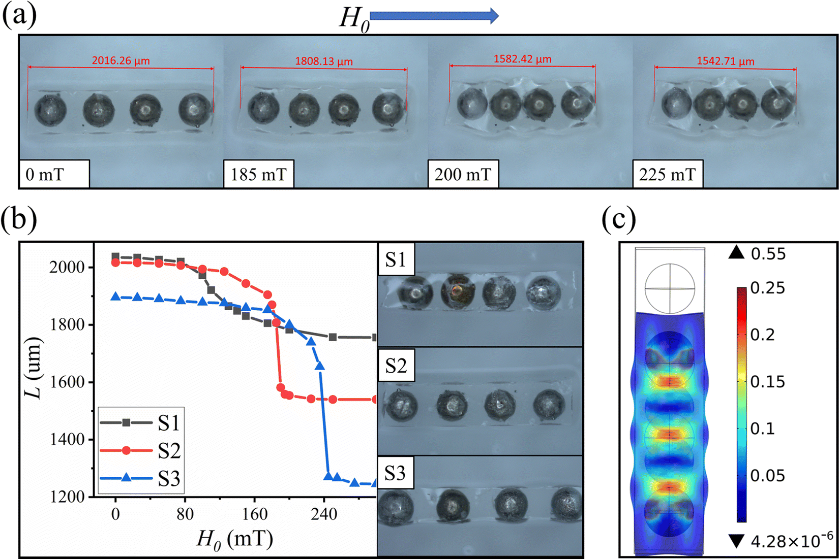 | ||
| Fig. 6 Compression deformation, (a) amount of compressive deformation at different magnetic field strengths. (b) Relationship between the spacing of adjacent soft magnetic particles and compression deformation. (c) Numerical simulation plot of the deformation of each part of the polymer matrix. | ||
As can be seen in Fig. 6(a), the length of this material is negatively correlated with the strength of the applied uniform magnetic field. The slope of the compressive deformation curve is large in the region where the magnetic field ranges from 185 mT to 225 mT. Therefore, the compression deformation is very responsive to the magnetic field in this range of the applied magnetic field strength. As shown in Fig. 6(b), the larger the spacing between adjacent soft magnetic particles, the larger the range of compression and deformation, and the larger the applied magnetic field required for compression and deformation. In contrast, the smaller the spacing between the soft magnetic particles, the smoother the compression and deformation, and the faster the response to the applied magnetic field.
As shown in Fig. 7, when the magnetic particles are arranged at an angle to the direction of the external magnetic field, the magnetic particles are also subjected to a magnetic moment, which drives the magnetic particles to rotate in the direction of the magnetic field. Eventually, the polymer matrix bends in the direction of the magnetic field under the action of the magnetic particles. Fig. 7(a). shows the relationship between the magnetic field strength and the amount of bending of the polymer matrix. As shown in Fig. 7(b), the relationship between the arrangement spacing of the magnetic particles and the amount of bending of the polymer matrix is demonstrated. In addition, the bending deformation of the polymer matrix was visualized using the numerical simulation method in Section 3.4, and the simulation results are shown in Fig. 7(c).
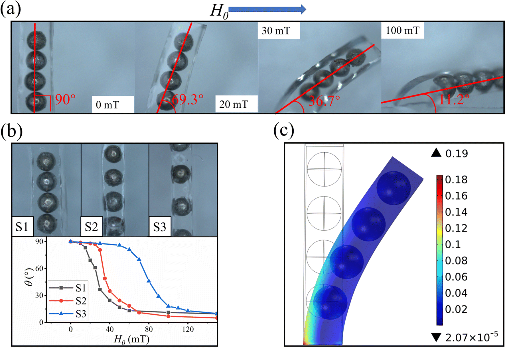 | ||
| Fig. 7 Bending deformation, (a) amount of bending deformation under different uniform magnetic fields. (b) Relationship between the spacing of adjacent soft magnetic particles and bending deformation. (c) Numerical simulation of the deformation of each part of the polymer matrix. | ||
As can be seen in Fig. 7(a), the bending deformation is positively correlated with the strength of the applied uniform magnetic field. Compared with the compression deformation mentioned above, the bending deformation is smoother and the magnetic field required for bending deformation is smaller, so the response to the magnetic field is faster and more stable. In addition, from Fig. 7(b), the larger the spacing between adjacent soft magnetic particles, the greater the uniform magnetic field strength required for the bending deformation, and therefore the lower the sensitivity, but the smoother the bending deformation, and therefore the better the robustness. At the same time, the slope of the bending curve is the largest when the bending angle is 45°.
Furthermore, when the compression on both sides of the polymer matrix is asymmetric, this causes the polymer matrix to bend toward the side with less compression. Therefore, as shown in Fig. 8, composites with compressive bending deformation were prepared in which the magnetic particles within the material were aligned parallel along one side of the polymer matrix, and therefore the compression amount on both sides of the polymer matrix was asymmetric. Fig. 8(a) shows the relationship between the external magnetic field strength and the amount of bending of the polymer matrix. Fig. 8(b) shows the relationship between the thickness of the polymer matrix and its bending amount. In addition, the amount of deformation of each part of the polymer matrix was visualized using the numerical simulation method mentioned in Section 3.4, and the simulation results are shown in Fig. 8(c).
 | ||
| Fig. 8 Compression bending deformation, (a) Compressive bending deformation at different strengths of the uniform magnetic field. (b) Relationship between the thickness of the polymer matrix and the compressive bending deformation. (c) Numerical simulation of the deformation of each part of the polymer matrix. | ||
In Fig. 8(a), the bending angle of the samples is positively correlated with the strength of the applied uniform magnetic field. In this case, the compressive bending deformation requires a larger magnetic field compared to the bending deformation shown in Fig. 7, and therefore the sensitivity to the response of the magnetic field is low. From Fig. 8(b), it can be concluded that the smaller the thickness of the polymer matrix, the smaller the uniform magnetic field strength required for bending deformation, and therefore the faster the response to the magnetic field, but the compression bending deformation curve is not smooth.
3.2. Deformation mechanism
In the previous section, we demonstrated the effect of the magnetic particle arrangement in composites on their deformation. In this section, we use the numerical model from Section 3.4 to model the relationship between the soft magnetic particle arrangement and the deformation. Here the radius of the magnetic particles is uniformly set to R = 180 um. The magnetic permeability is obtained from Fig. 3(f).As shown in Fig. 9(a), four soft magnetic particles are arranged parallel to the x-axis in the x–y plane, while there is an applied uniform magnetic field H0 in the x-positive direction with a strength of 100 mT. Here, the spacing between adjacent soft magnetic particles is set to D. In Fig. 9(b), the magnitudes of magnetic forces Fm3 and Fm4 are calculated for spacing D within [0.2R, 2R] where Fm3 and Fm4 are the magnetic forces of the soft magnetic particles P3 and P4, respectively. Where the magnetic force points to the origin as the positive.
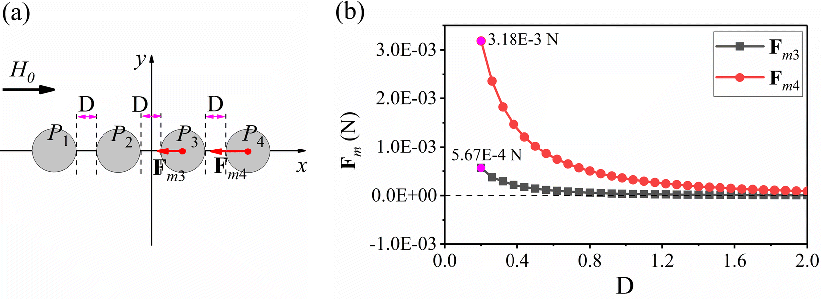 | ||
| Fig. 9 Magnitude of magnetic force between adjacent soft magnetic particles at different spacings. (a) Schematic diagram of the numerical simulation. (b) Magnitude of the magnetic force at different spacings. | ||
From Fig. 9(b), the magnitude of the magnetic force is negatively correlated with the spacing between the adjacent soft magnetic particles. This indicates that the closer the arrangement between the soft magnetic particles, the more sensitive the compressive deformation is, but the maximum compressive deformation decreases as the arrangement gap becomes smaller. This is also well illustrated in Fig. 6(b). Also Fig. 9(b) shows that the magnetic force of P4 is much larger than that of P3, which indicates that the compressive deformation is mainly caused by the two soft magnetic particles at the endpoints.
Also as shown in Fig. 10(a), located in the x–y plane, four soft magnetic particles were arranged in rows on the x-axis with the spacing between adjacent soft magnetic particles set to R and the size of 180 um. As shown in Fig. 10(b), the magnetic force magnitudes of Fm3 and Fm4 were calculated for a uniform magnetic field at H0[0, 200 mT] where Fm3 and Fm4 are the magnetic forces of the soft magnetic particles P3 and P4, respectively. The magnetic force direction is positive by pointing to the origin of the coordinate axis.
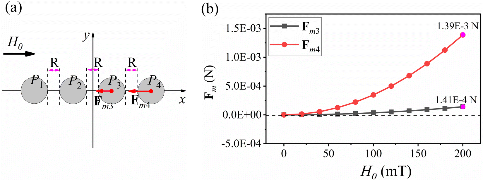 | ||
| Fig. 10 Magnitude of the magnetic force of soft magnetic particles under different strengths of the applied uniform magnetic field. (a) Schematic diagram of the numerical simulation and (b) magnitude of the magnetic force at different uniform magnetic field strengths. | ||
Fig. 10(b) shows that the magnitude of the magnetic force of P3 and P4 is positively correlated with the strength of the applied uniform magnetic field when adjacent spacing is the same.
Similarly, in order to investigate the bending deformation mechanism, as shown in Fig. 11(a), located in the x–y plane, four magnetic particles are arranged parallel to the straight-line l. Here the angle between l and the positive direction of the x-axis is set to θm. There also exists an applied uniform magnetic field H0 in the x-positive direction with a magnitude of 50 mT. As shown in Fig. 11(b), the magnetic moment Tm curves generated by four soft magnetic particles are calculated within the angle θm ∈ [0, 90] where the spacing of adjacent magnetic particles is set to D, and their magnitudes are 0.25R, 0.5R, 0.75R, and R. Here R is the radius of the soft magnetic particle, and the counterclockwise direction is considered as the positive direction of the magnetic moment.
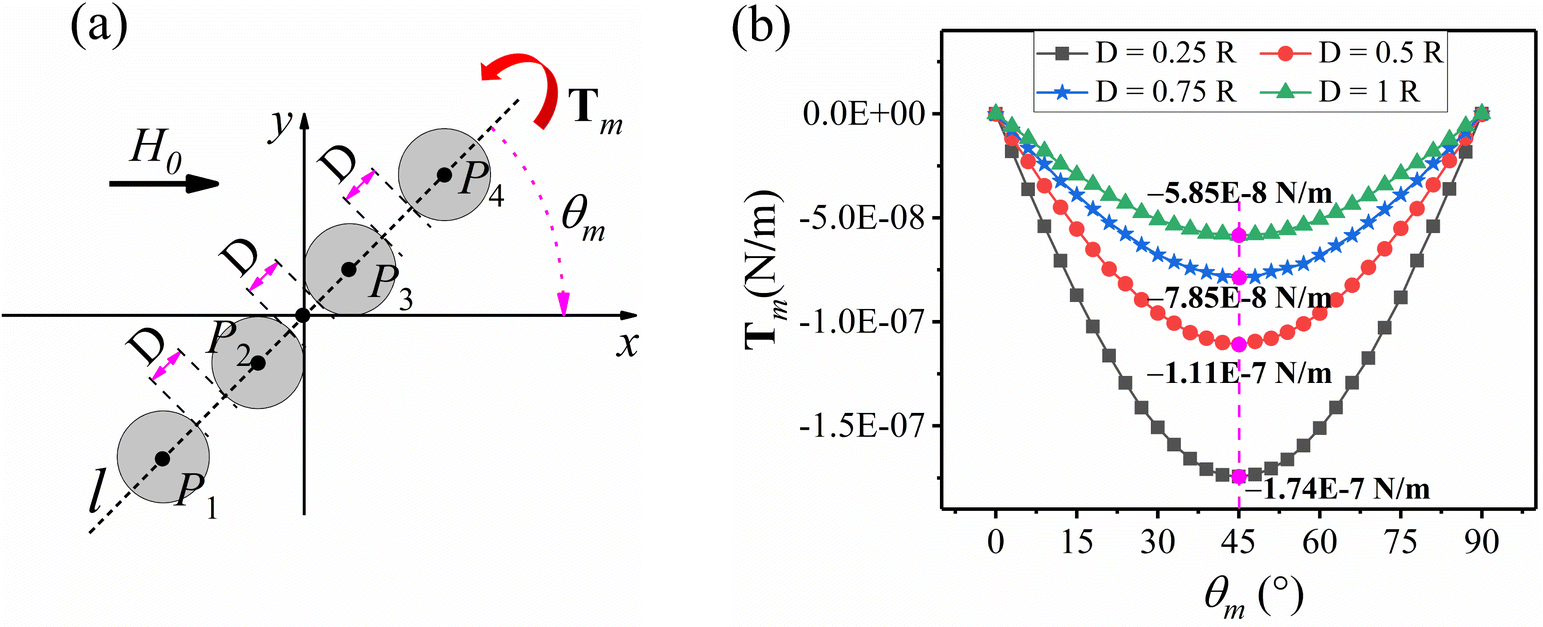 | ||
| Fig. 11 Magnitude of the magnetic moment at the different spacings between adjacent soft magnetic particles. (a) Schematic diagram of the numerical simulation. (b) Magnitude of the magnetic moment at different spacings. | ||
It can be seen from Fig. 11(b) that at the same applied uniform magnetic field strength, the magnetic moment Tm is maximum at a bending angle of 45°, while the magnitude of the magnetic moment Tm is 0 at a bending angle of 0° or 90. This indicates that the bending deformation is most sensitive at 45°, while the magnitude of the magnetic moment Tm is negatively correlated with the spacing between adjacent soft magnetic particles. This indicates that the closer the arrangement between the magnetic particles, the more sensitive the bending deformation is under the same applied magnetic field. All of the above conclusions can be verified in Fig. 7(b).
Also shown in Fig. 12(a), located in the xy plane, four magnetic particles are arranged parallel to line l, where the angle between l and the y-axis is θm. Let the distance between adjacent soft magnetic particles be R, and R is the radius of the soft magnetic particles. As shown in Fig. 12(b), when the included angle θm ∈ [0, 90], the magnetic moment Tm generated by 4 magnetic particles is calculated. The magnetic moment Tm is positive in the counterclockwise direction. Here, in order to study the magnitude of the magnetic moment under different external magnetic fields, H0 is taken as 25 mT, 50 mT, 75 mT and 100 mT respectively.
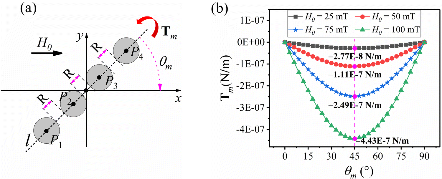 | ||
| Fig. 12 The magnitude of the magnetic moment under different applied uniform magnetic field strengths. (a) Schematic diagram of the numerical simulation. (b) Magnitude of the magnetic moment under different uniform magnetic field strengths. | ||
It can be seen from Fig. 12(b) that under the same spacing, the magnitude of the magnetic moment Tm is positively correlated with the strength of the applied uniform magnetic field.
3.3. Design of magnetically-controlled flexible micro-robot
In this section, we design magnetically controlled flexible micro-robots by applying several basic deformations from Section 4.1.As shown in Fig. 13, a magnetically controlled flexible microrobot with a swimming function was designed using the compression deformation of Fig. 8. As shown in Fig. 13(b), when an external magnetic field is applied, the magnetically controlled flexible micro-robot undergoes compression bending, which drives the two ends of the tail to oscillate inward. When the external magnetic field disappears, the magnetically-controlled flexible micro-robot returns to its original state, thus driving the two ends of the tail to swing outward. Thus, as shown in Fig. 13(c), when the external magnetic field is applied reciprocally, the tail of the magnetically controlled flexible micro-robot oscillates reciprocally, thus driving the magnetically controlled flexible micro-robot to move previously. Here swimming demonstration refer to Supplementary Video 1 (ESI†).
 | ||
| Fig. 13 Swimming design of a magnetically controlled flexible micro-robot (a) Schematic diagram of the shape of the magnetically controlled flexible micro-robot. (b) Schematic diagram of the swimming of the magnetically controlled flexible micro-robot. (c) Simulation diagram of swimming of magnetically-controlled flexible micro-robot. | ||
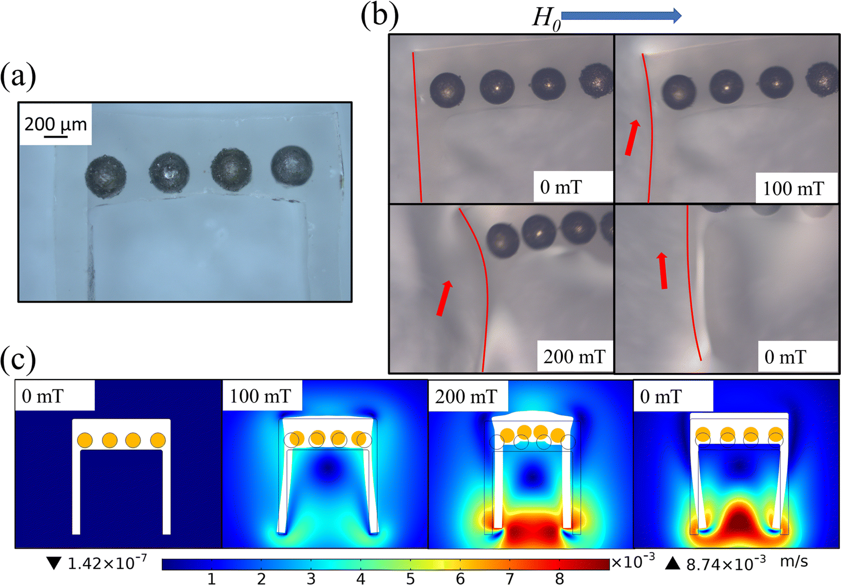
Also as shown in Fig. 14(a), the above swimming magnetically controlled flexible micro-robot has a transport function. When a uniform magnetic field is applied in the horizontal direction, the polymer matrix bends and drives the tail inward, thus allowing the tail to grip the object. When the applied uniform magnetic field is kept constant and a small gradient field B0 is applied, the magnetically controlled flexible micro-robot will carry the target object and move in the direction of the gradient of B0. Referring to the numerical simulation of the deformation of the polymer matrix in Fig. 14(b), it is shown that the spacing between the two end tails decreases under the action of the applied uniform magnetic field, thus providing a clamping function. Transport demonstration refers to Supplementary Video 2 (ESI†).
 | ||
| Fig. 14 Transportation design of magnetically-controlled flexible micro-robot (a) Schematic diagram of magnetically controlled flexible micro-robot transportation. (b) Deformation simulation diagram of the magnetically controlled flexible micro-robot. | ||
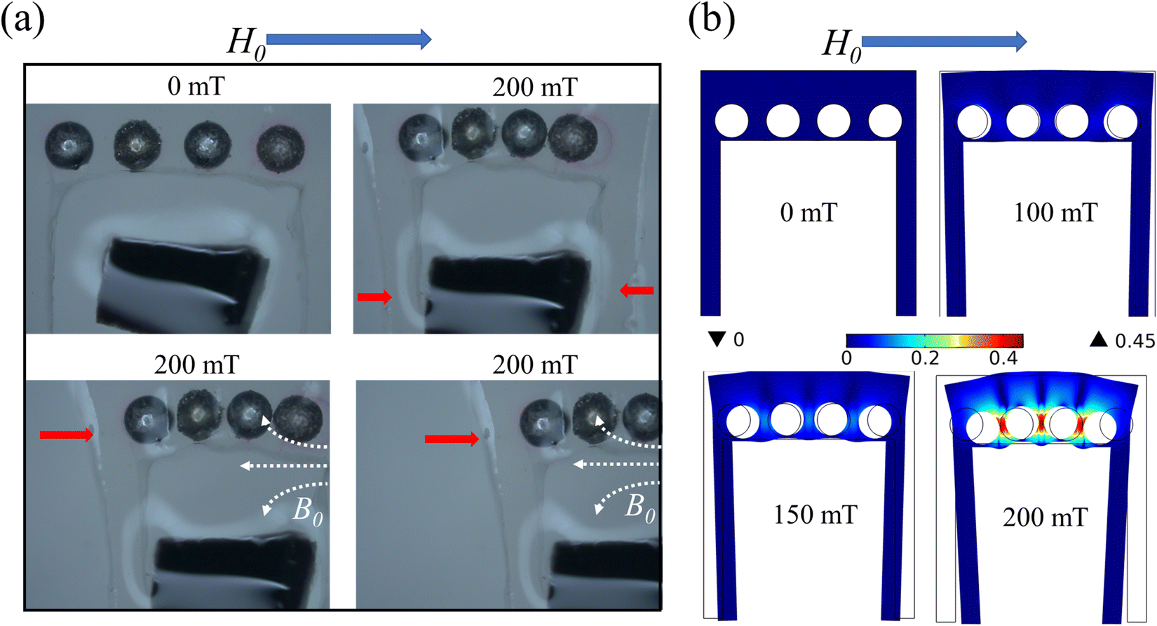
As shown in Fig. 15, a magnetically controlled flexible microrobot with a clamping function was designed using the bending deformation of Fig. 7. When a uniform magnetic field is applied, the chain of magnetic particles in the upper and lower parts bends inward, thus achieving the clamping function. As shown in Fig. 15(b), the deformation of each part of the polymer matrix under a uniform magnetic field is simulated. Refer to Supplementary Video 3 (ESI†) for the clamping demonstration.
 | ||
| Fig. 15 Clamping design of magnetically controlled flexible micro-robot (a) Clamping of magnetically controlled flexible microrobots. (b) Simulation diagram of magnetically controlled flexible micro-robot clamping deformation. | ||
4. Conclusions
In this paper, we report on a composite material based on programmed magnetic powder arrangements that can produce fast, reversible, and programmable shape transformations under magnetic fields. In addition, we investigate this composite's magnetically controlled deformation mechanism through experiments and numerical simulations. Based on the excellent deformation properties of this material, we designed magnetically controlled flexible micro-robots with swimming, transport, and gripping functions. This method allows the preparation of magnetically controlled flexible micro-robots with very small dimensions. In addition, the polymer matrix is naturally cured and uses few soft magnetic particles, and there is no need to repeat the preparation of magnetic axes, which reduces the manufacturing conditions and manufacturing costs. As a result, this paper provides a new idea for the preparation of magnetically controlled flexible micro-robots.Data availability
The data that support the findings of this study are available from the corresponding author upon reasonable request.Ethics statement
The paper does not contain any studies involving human or animal participants.Conflicts of interest
The authors declare that there is no conflict of interest.Acknowledgements
This research was funded by the Natural Science Foundation of Hunan Province (grant no. 2020JJ5545), the Scientific Research Foundation of Hunan Provincial Education Department (grant no. 21B0155), and the Key Project of Research and Development Plan of Hunan Province (grant no. 2021GK2025). The authors are grateful for the support.References
- L. Hines, K. Petersen, Z. L. Guo and M. Sitti, Adv. Mater., 2016, 29, 1603483 CrossRef.
- M. Sitti, H. Ceylan, W. Hu, J. Giltinan, M. Turan, S. Yim and E. Diller, Proc. IEEE, 2015, 103, 205–224 CAS.
- B. J. Nelson, I. K. Kaliakatsos and J. J. Ioannis, Annu. Rev. Biomed. Eng., 2010, 12, 55–85 CrossRef CAS.
- D. L. Rus and M. T. Tolley, Nature, 2015, 521, 467–475 CrossRef CAS PubMed.
- Q. L. Zhu, C. Du, Y. Dai, M. Daab, M. Matejdes, J. Breu, W. Hong, Q. Zheng and Z. L. Wu, Nat. Commun., 2020, 11, 5166 CrossRef CAS PubMed.
- L. Hines, K. Petersen and M. Sitti, Adv. Mater., 2016, 28, 3690–3696 CrossRef CAS PubMed.
- I. Must, F. Kaasik, I. Põldsalu, L. Mihkels, U. Johanson, A. Punning and A. Aabloo, Adv. Eng. Mater., 2015, 17, 84–94 CrossRef CAS.
- Q. Zhao, J. W. C. Dunlop, X. Qiu, F. Huang, Z. Zhang, J. Heyda, J. Dzubiella, M. Antonietti and J. Yuan, Nat. Commun., 2014, 5, 4293 CrossRef PubMed.
- S. Maeda, Y. Hara, T. Sakai, R. Yoshida and S. Hashimoto, Adv. Mater., 2007, 19, 3480–3484 CrossRef CAS.
- R. Taheri-Ledari, K. Valadi, S. Gharibi and A. Maleki, Mater. Res. Bull., 2020, 130, 110946 CrossRef CAS.
- V. Soltaninejad, M. R. Ahghari, R. Taheri-Ledari and A. Maleki, Langmuir, 2021, 37, 4700–4713 CrossRef CAS PubMed.
- S. Felton, M. Tolley, E. Demaine, D. Rus and R. Wood, Science, 2014, 345, 644–646 CrossRef CAS.
- H. W. Huang, M. S. Sakar, A. J. Petruska, S. Pané and B. J. Nelson, Nat. Commun., 2016, 7, 12263 CrossRef CAS.
- S. Iamsaard, S. J. Aßhoff, B. Matt, T. Kudernac, J. J. L. M. Cornelissen, S. P. Fletcher and N. Katsonis, Nat. Chem., 2014, 6, 229–235 CrossRef CAS PubMed.
- J. Mu, C. Hou, H. Wang, Y. Li and M. Zhu, Sci. Adv., 2015, 1, e1500533 CrossRef PubMed.
- V. Soltaninejad and A. Maleki, J. Photochem. Photobiol., A, 2021, 404, 112906 CrossRef CAS.
- R. V. Martinez, C. R. Fish, X. Chen and G. M. Whitesides, Adv. Funct. Mater., 2012, 22, 1376–1384 CrossRef CAS.
- B. Jang, E. Gutman, N. Stucki, B. F. Seitz, P. D. Wendel-García, T. Newton, J. Pokki, O. Ergeneman, S. Pané, Y. Or and B. J. Nelson, Nano Lett., 2015, 15, 4829–4833 CrossRef CAS.
- R. Fuhrer, C. M. Schumacher, M. Zeltner and W. J. Stark, Adv. Funct. Mater., 2013, 23, 3845–3849 CrossRef CAS.
- V. Q. Nguyen, A. S. Ahmed and R. V. Ramanujan, Adv. Mater., 2012, 24, 4041–4054 CrossRef CAS.
- T. Kimura, Y. Umehara and F. Kimura, Soft Matter, 2012, 8, 6206–6209 RSC.
- Q. Song, H. Guo, C. Jie, F. Jie, C. Hu, Y. Miao and Z. L. Wang, Nanoscale, 2018, 10, 4745–4752 RSC.
- R. Dreyfus, J. Baudry, M. L. Roper, M. Fermigier, H. A. Stone and J. Bibette, Nature, 2005, 437, 862–865 CrossRef CAS.
- H. Lu, Z. Mei, Y. Yang, H. Qiang and Y. Shen, Nat. Commun., 2018, 9, 3944 CrossRef.
- S. Fusco, M. S. Sakar, S. Kennedy, C. Peters, R. Bottani, F. Starsich, A. Mao, G. A. Sotiriou, S. Pané and S. E. Pratsinis, Adv. Mater., 2014, 26, 952–957 CrossRef CAS PubMed.
- W. Hu, G. Z. Lum, M. Mastrangeli and M. Sitti, Nature, 2018, 554, 81–85 CrossRef CAS.
- B. Yja, C. Rh, X. Yan, B. Jya, B. Xla, B. Yla, B. Xha, B. Qca and L. Liang, Nano Energy, 2021, 87, 106169 CrossRef.
- C. S. X. Ng, M. W. M. Tan, C. Xu, Z. Yang, P. S. Lee and G. Z. Lum, Adv. Mater., 2021, 33, 2003558 CrossRef CAS.
- S. V. Kankanala and N. Triantafyllidis, J. Mech. Phys. Solids, 2004, 52, 2869–2908 CrossRef CAS.
- Y. Kim, H. Yuk, R. Zhao, S. A. Chester and X. Zhao, Nature, 2018, 558, 274–279 CrossRef CAS.
- E. Diller, J. Zhuang, G. Z. Lum, M. R. Edwards and M. Sitti, Appl. Phys. Lett., 2014, 104, 1121–1122 CrossRef.
- G. Z. Lum, Z. Ye, X. Dong, H. Marvi, O. Erin, W. Hu and M. Sitti, Proc. Natl. Acad. Sci. U. S. A., 2016, 113, E6007 CrossRef CAS.
- R. Mueller, S. Huang, D. Borin, Y. Odenbach and M. Schuemann, Smart Mater. Struct., 2017, 26, 095018 CrossRef.
- Q. Wen, Y. Wang and X. Gong, Smart Mater. Struct., 2017, 26, 075012 CrossRef.
- M. Yu, S. Qi, J. Fu and M. Zhu, Appl. Phys. Lett., 2015, 107, 111901 CrossRef.
- T. Xu, J. Zhang, M. Salehizadeh, O. Onaizah and E. Diller, Sci. Robot., 2019, 4, eaav4494 CrossRef.
- J. Kim, E. C. Su, S. E. Choi, H. Lee, J. Kim and S. Kwon, Nat. Mater., 2011, 10, 747–752 CrossRef CAS PubMed.
- H. Ceylan, I. C. Yasa and M. Sitti, Adv. Mater., 2016, 29, 1605072 CrossRef.
- K. Danas, S. V. Kankanala and N. Triantafyllidis, J. Mech. Phys. Solids, 2011, 60, 120–138 CrossRef.
- A. Dorfmann and R. W. Ogden, Acta Mech., 2004, 167, 13–28 CrossRef.
- S. V. Kankanala and N. Triantafyllidis, J. Mech. Phys. Solids, 2004, 52, 2869–2908 CrossRef CAS.
- Z. Guo, X. Shi, Y. Chen, H. Chen, X. Peng and P. Harrison, Mech. Mater., 2014, 70, 1–17 CrossRef.
Footnote |
| † Electronic supplementary information (ESI) available. See DOI: https://doi.org/10.1039/d2ma01006b |
| This journal is © The Royal Society of Chemistry 2023 |