 Open Access Article
High-performance flexible supercapacitors based on potassium nickel(II) hexacyanoferrates(III) nanoparticles on carbon cloth as an electrode material
L. M.
Samyn
a,
T. S.
Lessa
a,
R. Suresh
Babu
 *a,
A.
Kalaivani
b,
T. M.
Barbosa
a and
A. L. F.
de Barros
 a
a
aLaboratory of Experimental and Applied Physics, Centro Federal de Educação Tecnológica Celso Suckow da Fonseca, Av. Maracanã 229, Rio de Janeiro, 20271-110, Brazil. E-mail: ryesbabu@gmail.com
bDepartment of Chemistry, Saveetha Engineering College, Thandalam, Chennai-602 105, Tamil Nadu, India
First published on 1st August 2023
Abstract
In this work, we report the synthesis of three-dimensional open-framework tunnels based on inorganic metal coordination compounds, such as potassium nickel(II) hexacyanoferrate(III) nanoparticles (PNHCF-NPs) by the co-precipitation method. The nanostructured material was characterized using various techniques, such as UV-Vis, FTIR, XPS, FESEM, EDS, and TEM. The prepared PNHCF-NPs were coated on carbon cloth and named PNHCF-NPs@CC. The electrochemical properties of PNHCF-NPs@CC were evaluated using cyclic voltammetry, galvanostatic charge–discharge, and electrochemical impedance spectroscopy techniques. In a 3-electrode cell configuration, PNHCF-NPs@CC electrode demonstrated high capacitance of 198.6 F g−1 (Na2SO4) and 168.8 F g−1 (K2SO4) at 0.4 A g−1, excellent rate performance of 88 F g−1 (Na2SO4) F g−1 and 89 F g−1 (K2SO4), even at 4 A g−1, and outstanding cyclic stability with ∼94% capacitance retention after 1000 cycles at 0.4 A g−1 for both electrolytes. The PNHCF-NP@CC hybrid showed high mechanical flexibility, superior electrical conductivity, and remarkably improved electrochemical capacitance, rendering it a promising flexible electrode material for use in high-performance supercapacitors.
Introduction
The rapid growth of miniature electronic devices and hybrid electric vehicles, the ever-increasing demand for clean and renewable energy sources, and the growing concern for the environment have encouraged intensive efforts to explore advanced energy storage and conversion devices.1,2 Over the last decade, efforts have been made to develop flexible energy storage devices, such as batteries, supercapacitors, and solar cells.3–8 Supercapacitors (SCs) are energy storage devices that present power density higher than batteries and energy density superior to conventional capacitors. These advantages have been attracting high attention to the application of SCs in electric vehicles, renewable energy sources, and wearable technologies and in a full generation of all-in-one portable electronic devices.9,10 Their superior performance of SCs is associated with their taking advantage of the combination of batteries and energy storage mechanisms of electrolytic capacitors during their operation. SCs are formed by two electrodes separated by non-conductive, but highly permeable, material. This separator is filled with an electrolyte doped with charges ready to chemically react with the electrode-coating material (as batteries) or to attach to the electrode surface (as electrolytic capacitors) during the charging process. In the first case, the energy storage device is called a pseudocapacitor and, in the second case, it is called an electric double-layer capacitor (EDLC).10,11Recently, transition metal hexacyanoferrates (MHCFs) are known for their high redox behavior and found applications in several areas, such as electrochemical sensors,12,13 batteries,14 and supercapacitors.15,16 Their unique structure, porosity, and high chemical stability make this material especially suitable for use in energy storage devices.17 Anna Lisowaka-Oleksiak et al.18 prepared a metal hexacyanoferrate network inside a polymer matrix for electrochemical capacitors with high capacitance, which resulted from the presence of inorganic networks.
So far, numerous kinds of MHCFs synthesized by different methods and fabricated on various base electrode materials have been reported, such as NiHCF,19 CuHCF,20 MnHCF,21 CoHCF,19,22etc. However, there have been no reports on the electrochemical behaviors of NiHCF on carbon cloth electrodes for SC applications. Although the electrochemical behaviors of MHCFs might be similar, it is still essential to examine such electroactive materials because the formation of MHCFs on electrode surfaces, as well as their electrochemical behaviors, may be different under different conditions.
In this work, we demonstrated a simple and low-cost synthesis of PNHCF-NP. The nanostructured material was characterized by UV-Vis, FTIR, Raman, XRD, XPS, FESEM, EDS, and TEM analysis. The electrochemical performance of the prepared PNHCF-NPs@CC was examined by electrochemical methods, such as cyclic voltammetry, galvanostatic charge–discharge (GCD), and electrochemical impedance spectroscopy (EIS). To the best of our knowledge, the use of carbon cloth as electrode substrate for the PNHCF-NPs deposition may improve the retention of charges during charging as the carbon cloth presents high porosity and good absorption, which imparts characteristics that are close to electrolytic capacitors for the manufactured electrodes.
2. Experimental
2.1. Chemicals
Carbon Cloth was purchased from Sainergy Fuel Cell India Pvt. Ltd. India. Potassium hexacyanoferrate, nickel nitrate, and potassium nitrate were procured from Sigma-Aldrich, USA. All other chemicals were analytical grade and used without further purification. All aqueous solutions were prepared with doubly distilled water.2.2. Methods
FTIR spectroscopy was performed using the Agilent Cary 630 FTIR spectrometer. Absorption spectra were analyzed with a SHIMADZU UV-2600i UV-Vis spectrophotometer. X-ray diffraction (XRD) analysis was performed on a Bruker model D8 using Cu Kα radiation. Morphology and size of the PNHCF-NPs were studied using FESEM (Model: Quattro S, Singapore); TEM images were obtained using a Hitachi, H7650 Microscope. Electrochemical characterization was performed on a multi-potentiostat (IVIUM Technologies) and a regular three-electrode cell was set up with Ag/AgCl, Pt mesh, and PNHCF-NPs electrodes as reference, counter, and working electrodes, respectively. All experiments were carried out at room temperature and ambient conditions. Two different electrolytes (Na2SO4 and K2SO4) were utilized and their performances were compared.2.3. Preparation of potassium nickel hexacyanoferrate nanoparticles (PNHCF-NPs)
PNHCF-NPs were prepared through the drop-wise addition of an aqueous solution of NiCl2 (70 mL of 10 mM solution) to K3Fe(CN)6 (70 mL of 50 mM solution) containing KCl (50 mM) while stirring.12 Once the addition finished, the mixture was strongly stirred for a few minutes and then filtered through a 0.4 μm Millipore cellulose filter paper. The precipitate was continuously washed with distilled water and then collected. After filtration, the precipitate was dried overnight at ambient temperature to obtain a powdered material.2.4. Electrode preparation
The working electrode was fabricated as follows. The as-prepared electroactive material (PNHCF-NPs), activated carbon (AC), and polyvinylidene fluoride (PVDF) (as a binder) were mixed in a mass ratio of 8![[thin space (1/6-em)]](https://www.rsc.org/images/entities/char_2009.gif) :
:![[thin space (1/6-em)]](https://www.rsc.org/images/entities/char_2009.gif) 1
1![[thin space (1/6-em)]](https://www.rsc.org/images/entities/char_2009.gif) :
:![[thin space (1/6-em)]](https://www.rsc.org/images/entities/char_2009.gif) 1 and dissolved in N-methyl-2-pyrrolidone (NMP). The purpose of the binder is to keep the active material attached to the electrode in the electrolyte solution. The prepared mixture was pasted onto 1 cm × 1 cm carbon cloth, followed by drying at 100 °C for 12 hours. The mass loading of electroactive materials on the carbon cloth was ∼2 mg cm−2. According to eqn (1), the specific capacitance (Cs) of the prepared samples was determined from the GCD curve.
1 and dissolved in N-methyl-2-pyrrolidone (NMP). The purpose of the binder is to keep the active material attached to the electrode in the electrolyte solution. The prepared mixture was pasted onto 1 cm × 1 cm carbon cloth, followed by drying at 100 °C for 12 hours. The mass loading of electroactive materials on the carbon cloth was ∼2 mg cm−2. According to eqn (1), the specific capacitance (Cs) of the prepared samples was determined from the GCD curve.| Q = I × t/m × ΔV | (1) |
3. Results and discussion
3.1 Physical characterization of PNHCF-NPs
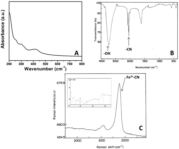
The UV-Vis spectrum of PNHCF-NPs presented strong absorbance at 300 nm and a broad absorption peak at ∼413 nm (Fig. 1A). The absorption at 300 nm can be assigned to the ligand to metal charge transfer (LMCT) band of [FeIII(CN)6], and that at 413 nm is due to the d-d transitions of NiII of PHCFNP. This observation is consistent with earlier reports,23 which indicate the formation of PNHCF-NPs.The FTIR spectrum of the PNHCF-NPs is shown in Fig. 1B. The band at 2097 cm−1 was attributed to the bridging cyanide (–CN) ligand, offering direct evidence that the bridged dinuclear (Ni, Fe) species were present in the complex. The data was also in agreement with the spectrum obtained by Neff for PB.24 Two peaks at 594 and 439 cm−1 corresponded to the stretching mode of ν(M–C) and bending mode of δ(M–CN), respectively.25 A broad band around 3444 cm−1 indicated the stretching vibrations of the hydroxyl (–OH) group, indicating that the interstitial or zeolitic water present in the complex, which resulted from the association of water molecules due to the H-bonding; this is similar to the absorption exhibited by PB.24
The oxidation states of PNHCF-NPs can be determined using Raman spectroscopy. In the Raman spectrum of PNHCF-NPs that are shown in Fig. 1C, it can be observed that the cyanide stretching modes are sensitive to the oxidation state of the coordinating iron. An intense band at 2175.8 cm−1 was attributed to the cyanide groups coordinated to Fe (III), indicating that the iron centers were mainly in the Fe3+ state. This observation is consistent with earlier reports.26 At low frequencies, the typical bands related to coordinated Fe (ν-(Fe–N) = 505 cm−1, δ(Fe–C–N) = 441 cm−1, δ(Fe–C–N) = 244.3 cm−1 and coordinated Ni (ν1(Ni–N) = 490 cm−1, (ν2(Ni–N) = 537 cm−1, δ(N–Ni–N) = 432 cm−1, δ1(N–Ni–N) = 194 cm−1 and δ2(N–Ni–N) = 268 cm−1, modes were also observed as shown in the inset of Fig. 1C.
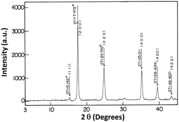
Fig. 2 shows the XRD analysis of NiHCF-NPs, which was used to demonstrate the crystallinity of nanoparticles. Peaks were observed at 17.4°, 24.7°, 35.1°, and 39.4°, which could correspond to the diffractions of (200), (220), (400), and (420) planes respectively, demonstrating the face-centered cubic (fcc) structure of NiHCF; the peak positions were similar to NiHCF pattern (JCPDS card, file no. 750037).12 The XRD peaks were broad and represented the presence of crystallites of nanometer dimensions. The average crystalline size, which was obtained from the half-width of the diffraction peaks by the Debye–Scherrer equation, was found to be ∼20 nm.
The PNHCF-NP complex was also characterized using the XPS technique to confirm the presence of different elements and their oxidation states. Fig. 3A presents the XPS elemental survey scans of the PNHCF-NPs. The Ni 2p peak was observed at 856.2 eV and 874.02 eV confirming the presence of Ni 2p3/2 and Ni 2p1/2 of Ni (II) species (Fig. 3B).27,28 The high-resolution XPS of Fe 2p exhibited two peaks at 708.5 eV and 721.4 eV, corresponding to Fe 2p3/2 and Fe 2p1/2 of Fe2+, respectively (Fig. 3C). The peaks at 710.0 and 723.5 eV (Fig. 3C) could be assigned to Fe 2p3/2 and Fe 2p1/2, corresponding to Fe (III) species, respectively.29–31 The XPS peaks observed at 284.5, 398.0, and 532.2 eV showed the presence of C, N, and O in the sample, which is in agreement with earlier reports.32
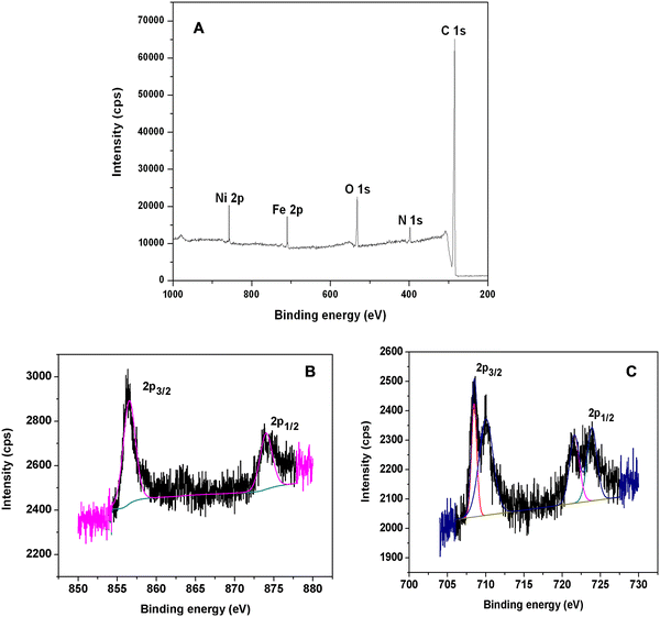 | ||
| Fig. 3 (A) XPS survey scan of PNHCF-NPs, (B) 2p3/2 and 2p1/2 peaks of Ni(II), and (C) 2p3/2 and 2p1/2 peaks of Fe(III). | ||
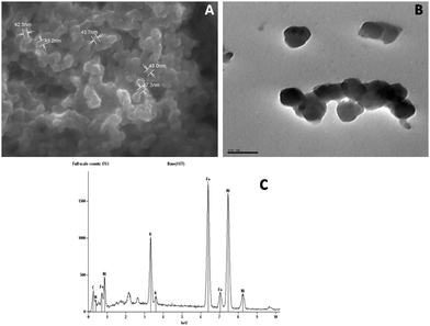
FESEM studies of PNHCF-NPs were carried out to understand the shape and size of the nanoparticles. The corresponding FESEM showed the presence of PNHCF-NPs with spherical morphology and the size distribution ranged between 20–50 nm (Fig. 4A). It can be seen that the average size of the PNHCF-NPs was <50 nm. The size and shape of the nanoparticles were also characterized and confirmed by HRTEM. The image depicts a uniform distribution of PNHCF-NPs. It indicates the formation of PNHCF-NPs with a sphere-like structure, and the size of each nanoparticle was found to be approximately 30 to 50 nm as shown in Fig. 4B. To identify the elemental composition of the PNHCF-NPs, EDS measurement was carried out. The corresponding spectra are shown in Fig. 4C. The appearance of the K, C, N, Ni, and Fe peaks confirms the existence of these elements in the PNHCF-NPs. The amount of Fe atoms is almost equal to the amount of Ni atoms. The proposed empirical formula of the PNHCF-NPs may be written as KNi[Fe(CN)6]. Therefore, the results suggest that alkali metal cations are present in the PNHCF-NPs.
3.2. Electrochemical characterization of PNHCF-NPs
The electrochemical performance of PNHCF-NPs electrodes was evaluated by cyclic voltammetry, galvanostatic charge–discharge (GCD), and electrochemical impedance spectroscopy (EIS). The cyclic voltammograms (CV) of the PNHCF-NPs electrode were examined at various sweep rates using two different electrolytes, such as aqueous solution of 1 M Na2SO4 and 1 M K2SO4 as shown in Fig. 5A and B. Cyclic voltammetry is a suitable method to evaluate the capacitive behavior of the electrode materials. As seen from Fig. 5A and B, the CVs of the PNHCF-NPs electrodes were cycled between voltage ranges: 0 to 1.0 V vs. Ag/AgCl in Na2SO4 and K2SO4 electrolytes. During the scans, reduction and oxidation peaks were observed; ferricyanide, Fe[(CN)6]4−/(Fe[(CN)6]3−), was formed at the surface of the PNHCF during cycling in the Na2SO4/K2SO4 aqueous solutions. The CV profiles demonstrated a typical pseudo-capacitance behavior through the appearance of a pair of redox peaks with the scanned potential for different scan rates as shown in Fig. 5A and B. The general electrochemical reaction mechanism for the PNHCF-NPs electrode in the Na2SO4 (or K2SO4) electrolyte was as follows:| M2NiII[FeII(CN)6↔MNiII[FeIII(CN)6 + e− + M+ M = K or Na | (2) |
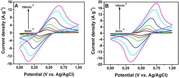 | ||
| Fig. 5 CVs of PNHCF-NPs electrode at different scan rates from 5, 10, 20, 50, 100, and 150 mV s−1. (A) Na2SO4 electrolyte and (B) K2SO4 electrolyte. | ||
The charge–discharge (CD) characteristics of the NHCF-NP in the 1-M Na2SO4 and 1-M K2SO4 electrolytes were investigated using chronopotentiometry from 0.2 to 0.6 V at various current densities. The corresponding results are shown in Fig. 6A and B, respectively. With the Na2SO4 electrolyte, the CD curve deviated in a non-linear fashion during charging, whereas it remained linear with the K2SO4 electrolyte. The curves presented large deviations, demonstrating that the capacitance was mainly governed by the redox reactions of MHCF. With increasing current densities from 1 A g−1 to 20 A g−1, a very small drop in the IR in higher current densities was obtained. The specific capacitances were calculated from GCD curves. The capacitances for the electrodes in both electrolytes were calculated using eqn (1). NHCF-NPs@CC electrode in the Na2SO4 electrolyte presented higher specific capacitances than the same electrode in the K2SO4 electrolyte, and their optimum performance was 198.6 F g−1 and 168.8 F g−1 at a current density of 0.4 A g−1 as shown in Fig. 7A and B. It is important to note that the NHCF-NPs@CC in Na2SO4 and K2SO4 electrolytes showed good specific capacitance retention value with an increase in the current density (from 0.4 to 4 A g−1). A comparison of the specific capacitances obtained for NHCF-NPs@CC in both electrolytes is summarized in Table 1.
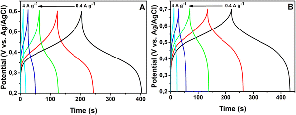 | ||
| Fig. 6 Galvanostatic charge–discharge curves of PNHCF-NPs electrode. (A) Na2SO4 electrolyte and (B) K2SO4 electrolyte. | ||
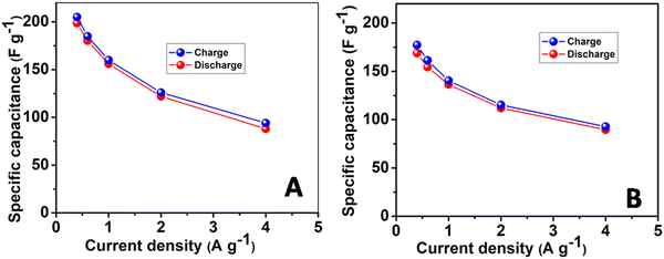 | ||
| Fig. 7 Specific capacity of the electrodes at different current densities in (A) Na2SO4 electrolyte and (B) K2SO4 electrolyte. | ||
| Current density (A g−1) | Na2SO4 (F g−1) | K2SO4 (F g−1) |
|---|---|---|
| 0.4 | 198.6 | 168.6 |
| 0.6 | 180.3 | 154.32 |
| 1 | 156 | 136.4 |
| 2 | 122 | 112 |
| 4 | 88 | 89.6 |
The long-term stability of the fabricated PNHCF-NPs@CC electrode was evaluated using the GCD method. The specific capacitances obtained from the GCD profiles in Na2SO4 and K2SO4 electrolytes are shown in Fig. 8A and B, respectively. As seen from the Figure, the PNHCF-NPs@CC electrode exhibited high stability with a small decrease in the capacitance and charge storage after 1000 cycles in both electrolytes. The specific capacitance of the electrode initially decreased and then became almost constant. After 1000 cycles, the capacitance decreased by only ∼6% of the initial capacitance, demonstrating outstanding cycle stability. This indicates that the repetitive cycling in either the Na2SO4 or K2SO4 electrolyte does not induce noticeable degradation of the PNHCF-NPs structure. This high stability over long cycles demonstrates that the fabricated electrode is suitable for practical applications.
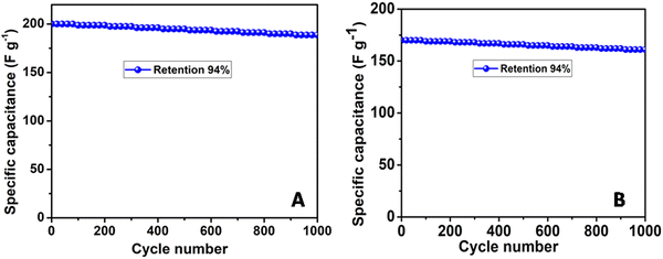 | ||
| Fig. 8 Long-term cycling stability of the PNHCP-NPs@CC electrode at current density of 0.4 A g−1 in the (A) Na2SO4 electrolyte and (B) K2SO4 electrolyte. | ||
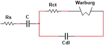
The behavior of the electrodes was also analyzed using EIS with both the electrolytes at the formal potential in the frequency range from 1 GHz to 1 Hz. The frequency response of each electrode/electrolyte system allowed the corresponding Nyquist curve to be plotted (Fig. 9). The correct interpretation of the obtained results allowed the assembly of an equivalent electrical circuit and allowed the description of the same behavior of the electrode/electrolyte system. The beginning of the curve illustrates the resistance of the electrolyte (Rs). In this paper, the Rs were considered to be both ohmic resistances, electrolyte, and internal resistance from the electrode materials, instead of only the electrolyte resistance (as is usually done); otherwise, the resistance would be the same for both experiments, given that the same electrolyte was utilized. The semicircle in the high-frequency region was associated with the charge transfer resistance (Rct), combined with two capacitors, that represents the capacity of the material. Its diameter often represents the resistance of the electrode material, combined with the resistance of the coated material and the current collectors. The diffusion of the ions is represented as straight lines in medium frequencies and can be described by the Warburg element (W). The equivalent circuit and respective values are shown in Fig. 10 and summarized in Table 2. It can be noted that the initial resistance is lower for K2SO4. The good conductivity of carbon cloth also contributes to the low resistance value for both electrodes. The experiment with Na2SO4 electrolyte also presents higher resistance (Rct) compared to that with K2SO4; this difference is likely associated with higher ionization energy.
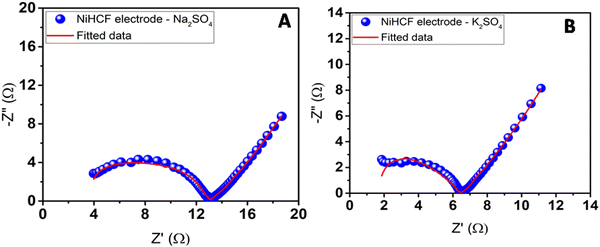 | ||
| Fig. 9 Nyquist plots for the coated PNHCF-NPs electrode with (A) Na2SO4 electrolyte and (B) K2SO4 electrolyte. | ||
| Electrolyte | R s (Ω) | R ct (Ω) | C 1 × 10⁻⁶ (F) | C 2 × 10⁻³ (F) | W (Ω−1) |
|---|---|---|---|---|---|
| Na2SO4 | 3.42 | 0.32 | 0.108 | 598.9 | 149.8 |
| K2SO4 | 0.93 | 5.37 | 0.136 | 475.9 | 188.9 |
4. Conclusions
In summary, PNHCF-NPs with a spherical structure were successfully prepared by a low-cost and convenient co-precipitation method. The PNHCF-NPs were physically characterized by various methods, such as UV-Vis, FTIR, XPS, FESEM, and EDS. The PNHCF-NPs thus obtained play an important role in ion insertion/desertion and electrolyte access. The electrochemical measurements were performed using two different electrolytes, namely, Na2SO4 and K2SO4, employing cyclic voltammetry, GCD, and EIS techniques. The high specific capacitances of the PNHCF-NPs@CC electrode of 198.6 F g−1 in Na2SO4 electrolyte and 168.8 F g−1 in the K2SO4 electrolyte were obtained at 0.4 A g−1, excellent rate performance of 88 F g−1 (Na2SO4) F g−1 and 89 F g−1 (K2SO4) were recorded even at 4 A g−1. It was found that the PNHCF-NPs@CC electrode was more electrochemically stable at up to 1000 GCD cycles in the Na2SO4 and K2SO4 electrolytes.Conflicts of interest
There are no conflicts to declare.Acknowledgements
Dr R. S. Babu wishes to acknowledge the Coordenação de Aperfeiçoamento de Pessoal de Nível Superior (CAPES) for financial support (88887.798322/2022-00) and Fundação de Amparo à Pesquisa do Estado do Rio de Janeiro (FAPERJ) for the financial support of the senior post-doctoral fellow (E-26/202.333/2021). Prof. A. L. F. de Barros wishes to acknowledge the Conselho Nacional de Desenvolvimento Científico e Tecnológico (CNPq) (301868/2017-4 and 407938/2018-4), the Financiadora de Estudos e Projetos (FINEP) (0647/18), and FAPERJ (E-26/210.965/2021, E-26/210.801/2021, E-26/245.307/2019, and E-26/241.202/2018) for partial support. This research work was also funded in part by the Coordenação de Aperfeiçoamento de Pessoal de Nível Superior - Brazil (CAPES) under Finance Code 001.References
- S. Fiorenti, J. Guanetti, Y. Guezennec and S. Onori, Modeling and experimental validation of a hybridized energy storage system for automotive applications, J. Power Sources, 2013, 241, 112–120 CrossRef CAS.
- D. Iannuzzi and P. Tricoli, Speed-based state-of-charge tracking control for metro trains with onboard supercapacitors, IEEE Trans. Power Electron., 2012, 27, 2129–2140 Search PubMed.
- C. Li, Q. Zhang, J. Sun, T. Li, E. Songfeng, Z. Zhu, B. He, Z. Zhou, Q. Li and Y. Yao, High-performance quasi-solid-state flexible aqueous rechargeable Ag−Zn battery based on metal-organic framework-derived Ag nanowires, ACS Energy Lett., 2018, 3, 2761–2768 CrossRef CAS.
- Q. Zhang, C. Li, Q. Li, Z. Pan, J. Sun, Z. Zhou, B. He, P. Man, L. Xie, L. Kang, X. Wang, J. Yang, T. Zhang, P. P. Shum, Q. Li, Y. Yao and L. Wei, Flexible and high-voltage coaxial-fiber aqueous rechargeable zinc-ion battery, Nano Lett., 2019, 19, 4032–4035 Search PubMed.
- Z. Shen, L. Luo, C. Li, J. Pu, J. Xie, L. Wang, Z. Huai, Z. Dai, Y. Yao and G. Hong, Stratified zinc-binding strategy toward prolonged cycling and flexibility of aqueous fibrous zinc metal batteries, Adv. Energy Mater., 2021, 11, 2100214 CrossRef CAS.
- Z. Shen, Z. Tang, C. Li, L. Luo, J. Pu, Z. Wen, Y. Liu, Y. Ji, J. Xie, L. Wang, Y. Yao and G. Hong, Precise proton redistribution for two-electron redox in aqueous zinc/manganese dioxide batteries, Adv. Energy Mater., 2021, 11, 2102055 CrossRef CAS.
- P. Thounthong, Model based-energy control of a solar power plant with a supercapacitor for grid-independent applications, IEEE Trans. Energy Conversion, 2011, 26, 1210–1218 Search PubMed.
- N. S. Noorasid, F. Arith, A. N. Mustafa, M. A. Azam, S. Mahalingam, P. Chelvanathan and N. Amin, Current advancement of flexible dye sensitized solar cell: A review, Optik, 2022, 254, 168089 CrossRef CAS.
- A. Gee, F. Robinson and R. Dunn, Analysis of battery lifetime extension in a smallscale wind-energy system using supercapacitors, IEEE Trans. Energy Conversion, 2013, 28, 24–33 Search PubMed.
- G. Wang, L. Zhang and J. Zhang, A review of electrode materials for electrochemical supercapacitors, Chem. Soc. Rev., 2012, 41, 797–828 RSC.
- X. Peng, L. Peng, C. Wu and Y. Xie, Two dimensional nanomaterials for flexible supercapacitors, Chem. Soc. Rev., 2014, 43, 3303–3323 RSC.
- R. S. Babu, P. Prabhu and S. S. Narayanan, Selective electrooxidation of uric acid in presence of ascorbic acid at a room temperature ionic liquid/nickel hexacyanoferarrate nanoparticles composite electrode, Colloids Surf., B, 2011, 88, 755–763 CrossRef CAS PubMed.
- R. S. Babu, P. Prabhu and S. S. Narayanan, Electrocatalytic oxidation of acetaminophen using 1-ethyl-3-methylimidazolium tetrafluoroborate-nickel hexacyanoferrate nanoparticles gel modified electrode, J. Chem. Pharm. Res., 2012, 4, 3592–3600 Search PubMed.
- C. D. Wessells, R. A. Huggins and Y. Cui, Copper hexacyanoferrate battery electrodes with long cycle life and high power, Nat. Commun., 2011, 2, 550 CrossRef PubMed.
- J. Chen, K. Huang and S. Liu, Insoluble metal hexacyanoferrates as supercapacitor electrodes, Electrochem. Commun., 2008, 10, 1851–1855 CrossRef CAS.
- Y. Wang, Y. Yang, X. Zhang, C. Liu and X. Hao, One-step electrodeposition of polyaniline/nickel hexacyanoferrate/sulfonated carbon nanotubes interconnected composite films for supercapacitor, J. Solid State Electrochem., 2015, 19, 3157–3168 CrossRef CAS.
- N. K. A. Venugopal and J. Joseph, Electrochemically formed 3D hierarchical thin films of cobalt-manganese (Co-Mn) hexacyanoferrate hybrids for electrochemical applications, J. Power Sources, 2016, 305, 249–258 CrossRef.
- A. Lisowska-Oleksiak and A. P. Nowak, Metal hexacyanoferrate network synthesized inside polymer matrix for electrochemical capacitors, J. Power Sources, 2007, 173, 829–836 CrossRef CAS.
- M. A. Maier, R. S. Babu, D. M. Sampaio and A. L. F. de Barros, Binder-free polyaniline interconnected metal hexacyanoferrates nanocomposites (Metal = Ni, Co) on carbon fibers for flexible supercapacitors, J. Mater. Sci.: Mater. Electron., 2017, 28, 17405–17413 CrossRef CAS.
- X. Li, A. Wu, C. Gao, Z. K. Li and S. W. Lee, Copper hexacyanoferrate as a long-life cathode for aqueous aluminum ion batteries, Mater. Today Energy, 2023, 31, 101205 CrossRef CAS.
- R. S. Babu, A. L. F. de Barros, M. A. Maier, D. M. Sampaio, J. Balamurugan and J. H. Lee, Novel polyaniline/manganese hexacyanoferrate nanoparticles on carbon fiber as binder-free electrode for flexible supercapacitors, Composites, Part B, 2018, 143, 141–147 CrossRef CAS.
- F. Zhao, Y. Wang, X. Xu, Y. Liu, R. Song, G. Lu and Y. Li, Cobalt hexacyanoferrate nanoparticles as a high-rate and ultrastable supercapacitor electrode material, ACS Appl. Mater. Interfaces, 2014, 6, 11007–11012 CrossRef CAS PubMed.
- M. Yang, J. Jiang, Y. Lu, Y. He, G. Shen and R. Yu, Functional histidine/nickel hexacyanoferrate nanotube assembly for biosensor applications, Biomaterials, 2007, 28, 3408–3417 CrossRef CAS PubMed.
- D. Ellis, M. Eckhoff and V. D. Neff, Electrochromism in the mixed-valence hexacyanides. 1. Voltammetric and spectral studies of the oxidation and reduction of thin films of Prussian blue, J. Phys. Chem., 1981, 85, 1225–1231 CrossRef CAS.
- K. Nakamoto, Infrared and Raman spectra of inorganic and coordination compounds, John Wiley & Sons, Inc., New York, 1986 Search PubMed.
- K. M. Jeerage, W. A. Steen and D. T. Schwartz, Charge-density-dependent partitioning of Cs+ and K+ into nickel hexacyanoferrate matrixes, Langmuir, 2002, 18, 3620–3625 CrossRef CAS.
- Y. J. Yang, J. Dong, C. Zhang, X. Ding, Y. Li, H. Ren and F. Guo, Phosphotungstic acid assisted growth of nickel hexacyanoferrate on Ni foam for binder-free supercapacitor electrode, J. Electroanal. Chem., 2021, 895, 115537 CrossRef CAS.
- Y. J. Yang, Y. Li, X. Ding, C. Zhang, H. Ren, F. Guo and J. Dong, Synthesis of nickel hexacyanoferrate nanostructure on carbon cloth with predeposited nickel nanoparticles as precursor for binder-free high-performance supercapacitor electrodes, J. Alloys Compd., 2021, 871, 159510 CrossRef CAS.
- Y. J. Yang, M. Liu, C. Jiang, P. Yang, N. Wang, S. Chen and Y. Cheng, One-step hydrothermal growth of reduced graphene oxide/nickel hexacyanoferrate nanocomposite on Ni foam for binder-free supercapacitor electrode, J. Energy Storage, 2021, 44, 103462 CrossRef.
- Y. J. Yang, C. Jiang, N. Wang, S. Chen, Y. Cheng, P. Yang and M. Liu, In situ hydrothermal growth of manganese hexacyanoferrate with Ni foam as the sacrificing template for high-performance asymmetrical supercapacitor, Ionics, 2022, 28, 2957–2966 CrossRef CAS.
- T. R. I. Cataldi, G. E. D. Benedetto and A. Bianchini, X-ray photoelectron spectroscopic investigation and electrochemistry of polynuclear indium (III) hexacyanoferrate films, J. Electroanal. Chem., 1998, 448, 111–117 CrossRef CAS.
- T. Akitsu and Y. Einaga, Structures, magnetic properties, and XPS of one-dimensional cyanide-bridged CuII–NiII/PtII bimetallic assembly complexes, Inorg. Chim. Acta, 2007, 360, 497–505 CrossRef CAS.
| This journal is © The Royal Society of Chemistry 2023 |

