 Open Access Article
Creative Commons Attribution 3.0 Unported Licence
Metal dicarboxylates as anode materials for Li-ion batteries†
Matthew
Teusner
 *a,
Jitendra
Mata
b,
Bernt
Johannessen
 c,
Glen
Stewart
d,
Seán
Cadogan
d and
Neeraj
Sharma
 a
a
aSchool of Chemistry, The University of New South Wales, Kensington, NSW 2052, Australia. E-mail: m.teusner@unsw.edu.au
bAustralian Centre for Neutron Scattering (ACNS), Australia's Nuclear Science and Technology Organisation (ANSTO), New Illawarra Rd, Lucas Heights, NSW 2234, Australia
cAustralian Synchrotron, ANSTO, 800 Blackburn Rd, Clayton, VIC 3168, Australia
dSchool of Science, The University of New South Wales, Australian Defence Force Academy, Canberra, ACT 2600, Australia
First published on 5th July 2023
Abstract
Holistic investigations into the various mechanisms of battery electrodes are essential for the development of competitive and sustainable novel battery materials. Specifically, deeper insights into the relationship between the electrode nano and microstructure and electrochemical performance provide avenues for significantly increasing the performance of a material. Here we report the use of novel metal-dicarboxylate metal–organic frameworks made from abundant and inexpensive building blocks as anode materials for Li ion batteries. Additionally, in-depth characterisation of the produced electrodes using X-ray diffraction (XRD), small angle neutron scattering (SANS) and scanning electron microscopy (SEM) showed that the electrode nano and microstructures could be tuned through variations in the electrode formulation. Namely, dissolution of the active materials was found to be greater in water-based slurries as compared to NMP-based slurries. This led to better distribution and dispersion of the active material in the dried electrode, which showed strong correlation with an increase in the specific capacity of the material. In the case of iron(II) tartrate, an improvement of ∼430 mA h g−1 to ∼870 mA h g−1 was recorded. An additional benefit of this formulation approach is the ability to replace toxic NMP-based formulation with benign and green water-based formulation.
Introduction
Batteries play an essential role in the functioning of contemporary society, having application at the personal, household and industrial scale. In recent years, the need for batteries has only deepened as continued development in renewable energy infrastructure is essential to combat the looming climate challenges. This is because replacement of fossil fuel based energy sources with renewable energy sources, e.g. wind or solar, is contingent on the ability to store the intermittently generated energy. Currently, Li-ion batteries make up the vast majority of both household1 and grid2 stationary energy storage, and emerging technologies and consumer interest is accelerating the uptake.3 However, despite many advances, <10% of predicted global renewable energy storage requirements have been met.4One of the main bottlenecks in battery uptake is the limitations imposed by current Li-ion battery technology. Graphite, the conventional anode, suffers from a number of inherent shortcomings that are difficult to surmount. Firstly, due to its intercalation mechanism, the theoretical capacity for graphite is only 372 mA h g−1.5 Secondly, high purity graphite is required for Li-ion batteries, and the predominant purification processes are expensive and involve the use of significant quantities of HF,6 a highly toxic and environmentally unfriendly chemical. Finally, suitable graphite sources are relatively inaccessible globally, with the vast majority being located in only a few countries.6 It is likely that technological advances in purification processes will help to combat the high cost and allow for the use of additional graphite sources. However, this will not overcome the insurmountable limited theoretical capacity. Hence, alternative anode materials need to be developed to support the increasing demand for energy storage.
Metal organic frameworks (MOFs) have been the subject of much study as alternative anode materials for Li-ion batteries, demonstrating excellent energy density.7,8 One of the primary benefits of MOFs is their synthetic modularity, which allows for near-endless scope of accessible materials. Subsequently, far greater material tailoring is possible, allowing for better optimisation of desired features such as renewability, reduced toxicity, and cost,9–13 in addition to the electrochemical performance. Unfortunately, many MOFs suffer from issues such as low electronic conductivity, poor rate capability and low structural stability with intercalation.14–16 However, further research and optimisation can help overcome these shortcomings, e.g. development of conductive MOFs17 or MOFs that rely on conversion reactions as the Li storage mechanism. The latter improvement would also likely provide an increase in the capacity, as conversion type materials typically have higher capacity than intercalation type materials.18 However, it is difficult to find examples of confirmed conversion-type MOFs, perhaps due to the increased difficulty in probing the mechanism. One reported example of a conversion MOF is copper citrate,11 which was shown to undergo breakdown of the MOF structure during Li insertion.
In addition to the copper citrate, several other copper-carboxylate MOFs have been reported as Li-ion anode materials, including copper maleate,19–22 copper tartrate23 and copper citrate,11 with the copper maleate being the most studied to date. Of note, the reported capacity values for copper maleate vary significantly, i.e. 311,22 405,20 1338,21 and 145019 mA h g−1. Based on our previous works,22,23 the likely reason for this such disparity is because of the electrode nano and microstructure which in turn is related to the differences in how the electrodes are formulated. This is consistent with the knowledge that two different methods of electrode formulation were applied: one using the in situ reaction between maleic acid and the copper substrate, and the other using pre-synthesised copper maleate. The particle size, active material distribution and homogeneity will vary greatly between these two formulation methods, which has been shown to greatly affect the electrochemical performance for these materials.23 It is therefore clear that development of tools and techniques to study and optimise the electrode nano and microstructure is key to the success of these types of materials.
Exploitation of the space-filling property of liquids during electrode preparation is one avenue of nano and microstructural tuning and homogenisation. In Li–S battery research, the melt-diffusion process has been employed to create performance enhanced electrodes, by the diffusion of molten sulphur into a carbon framework.24–26 Firstly, this process allowed a higher active material loading to be achieved, while maintaining high active material utilisation. Furthermore, the highly porous carbon framework gave high conductivity which is essential when using poorly conductive active materials. It has also been shown that the carbon framework helps to supress the detrimental shuttle effect with cycling. Finally, this process also allows a solvent and binder free approach to electrode formulation. To the best of our knowledge, this concept has not been exploited outside of the Li–S space. This is understandable for conventional battery materials such as transition metal oxides and graphite, which are non-soluble. Their high conductivity also reduces the need to employ such a tuning tool. However, for soluble and poorly conductive active materials such many MOFs, dissolution in the electrode formulation solvent represents a promising avenue for nano and microstructural optimisation.
In this study, we develop the understanding of the electrochemical performance of previously examined metal carboxylates,11,21–23 and use the findings to develop new active materials and optimised electrode formulations. Firstly, the reported in situ reaction between the acid(s) and the copper substrate is critically probed using a series of ex situ copper + tartaric acid syntheses, unexpectedly revealing that two copper tartrate analogues are formed, depending on the reaction conditions. Furthermore, one analogue was highly water soluble, allowing active material dissolution during electrode formulation when using a water-based slurry method. Structural characterisation using scanning electron microscopy (SEM) and small and ultra-small angle neutron scattering (SANS and USANS) of the water-based electrode revealed significantly increased active material distribution and homogenisation than the N-methyl pyrrolidone (NMP)-based electrode. Furthermore, the nano and microstructural change was accompanied by a significant improvement in the electrochemical performance. Subsequently, a series of related metal–acid analogues were synthesised or purchased and formulated into water-based and NMP-based electrodes. Structural and electrode characterisation in combination with electrochemical testing demonstrated that solubility of the active material in the formulation solvent significantly increased the electrochemical performance.
Results and discussion
Pot synthesis of Cu TAR
![[double bond, length as m-dash]](https://www.rsc.org/images/entities/char_e001.gif) O stretch (1571 cm−1), the C–O stretching vibration (1358 and 1301 cm−1), the C–H stretching vibration (1112 cm−1) and the O–H stretching out of plane vibration (1059 cm−1). Conversely, significant differences were observed when compared to tartaric acid. Of specific note are the loss of the two sharp O–H stretches (3403 and 3322 cm−1) and the shift of the C
O stretch (1571 cm−1), the C–O stretching vibration (1358 and 1301 cm−1), the C–H stretching vibration (1112 cm−1) and the O–H stretching out of plane vibration (1059 cm−1). Conversely, significant differences were observed when compared to tartaric acid. Of specific note are the loss of the two sharp O–H stretches (3403 and 3322 cm−1) and the shift of the C![[double bond, length as m-dash]](https://www.rsc.org/images/entities/char_e001.gif) O stretch (1716 cm−1). Thermogravimetric analysis (TGA) of the copper tartrate hydrous showed approximately 7% mass loss up to 180 °C which is consistent with the loss of 2× H2O molecules from Cu2(C4H4O6)2(H2O)2. This suggests that the guest water was previously removed in the product recovery. The mass loss here is only approximate due to the overlap of the end of the dehydration and the start of the thermal decomposition, which begins around 180 °C and finishes by 300 °C. Following the thermal decomposition, a residual mass of 48.9% was measured, resulting in 41.9% mass loss due to thermal decomposition (based on 7.0% mass loss during dehydration). This is consistent with the reported mass loss during thermal decomposition for similar copper tartrate complexes.29
O stretch (1716 cm−1). Thermogravimetric analysis (TGA) of the copper tartrate hydrous showed approximately 7% mass loss up to 180 °C which is consistent with the loss of 2× H2O molecules from Cu2(C4H4O6)2(H2O)2. This suggests that the guest water was previously removed in the product recovery. The mass loss here is only approximate due to the overlap of the end of the dehydration and the start of the thermal decomposition, which begins around 180 °C and finishes by 300 °C. Following the thermal decomposition, a residual mass of 48.9% was measured, resulting in 41.9% mass loss due to thermal decomposition (based on 7.0% mass loss during dehydration). This is consistent with the reported mass loss during thermal decomposition for similar copper tartrate complexes.29
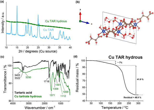 | ||
| Fig. 1 (a) XRD of copper tartrate and copper tartrate hydrous produced by copper–tartaric acid reaction. (b) Copper tartrate hydrous crystal structure, solved from single crystal XRD: CCDC number 927768. See Table S2 (ESI†) for crystallographic information. (c) FTIR spectra of tartaric acid (black) and copper tartrate hydrous (green). (d) Thermogravimetric analysis of copper tartrate hydrous. | ||
Previously, the electrode formulation conditions have been demonstrated to affect the electrode composition and microstructure for this in situ reaction.22 As an additional investigation, a series of syntheses with varying parameters were conducted, which demonstrated that the synthesis conditions (analogous to the formulation conditions) affected the reaction outcome (see ESI† for details). It is important to note that after product recovery the residual reaction mixture was dark brown in colour. This likely indicated that some decomposition/side products had been generated, which is consistent with the previously proposed theory that the increased capacity fade in the acid-derived electrodes is due to the presence of side products.22,23
SEM analysis of the electrodes revealed significant similarity between the water-based copper tartrate (Fig. S2, ESI†), the NMP-based copper tartrate hydrous (Fig. 2a) and the reported NMP-based copper tartrate electrode.23 Isolated 1–10 μm size particles of the active species were visible on the surface of the NMP-based electrodes. In contrast, the water-based copper tartrate hydrous electrode displayed significant particle size reduction (Fig. 2b). Submicron particles covered the entirety of the surface of the electrode, and fewer >5 μm particles were visible, which is consistent with increased distribution and dispersion of the active material throughout the electrode. A higher degree of electrode cracking was also observed for the water-based electrodes. This is likely due to either a less-optimised electrode formulation, or the impact of drying a water-based slurry.
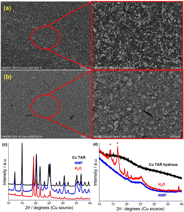 | ||
| Fig. 2 (a) and (b) SEM (200/1000x) of pristine copper tartrate hydrous electrodes made using an (a) NMP based slurry and (b) H2O based slurry. (c) and (d), XRD of parent material (black), and of NMP-based (blue) and water based electrodes (red) made from (c) copper tartrate and (d) copper tartrate anhydrous. Red asterisk denotes peaks from adhesive used to hold sample. NMP-based copper tartrate electrode data in (c) from previous publication.23 | ||
A change in the copper tartrate peak intensity ratios was observed between the two copper tartrate electrodes by XRD (Fig. S2b, ESI†), which likely indicates a change in the preferred orientation of the copper tartrate when deposited as electrodes. Minute changes in size of the copper tartrate crystallites was observed, based on peak width (Scherrer) analysis, with calculated values ranging between 20–40 nm based on the 111 and 411 reflections. For the copper tartrate hydrous (Fig. S2c, ESI†), the water-based electrode displayed small peaks at 2θ ∼19, 20 and 22° as well as a broad peak at ∼25°. These peaks overlap with those of copper tartrate, demonstrating both partial dehydration, as well as recrystallisation of the active material. The NMP-based electrode did not produce any distinct XRD peaks, similar to the parent material, although a broad peak around 25° was observed. It is probable that the broad peak in the NMP-based electrode is also from the copper tartrate formed by dehydration. Overall, both the active species precursor and the formulation method played a significant role in determining the electrochemical performance of the electrode. The water-based copper tartrate electrode (no active material dissolution, large particle size) displayed a similar (albeit slower) capacity climb to the reported NMP-based copper tartrate electrode,23 reaching only ∼470 mA h g−1 at cycle 100, compared to ∼628 mA h g−1 (Fig. 3a). The capacity climb is likely related to the evolution of the Li storage mechanism and is discussed below. In contrast, the water-based copper tartrate hydrous electrode (active material dissolution, small particle size) showed a greatly accelerated capacity climb, stabilising at ∼561 mA h g−1 at cycle 60. As the final (dried) electrodes contained the same active material, i.e. copper tartrate, this clearly indicates that the changes in the electrode structure with formulation (as discussed above) play a key role in the electrochemical performance. It is expected that the lower specific capacity of the water-based copper tartrate hydrous (compared to the NMP-based electrode) is due to the decreased active mass as a result of dehydration of the copper tartrate hydrous, i.e. 1 g of copper tartrate hydrous results in ∼0.88 g of copper tartrate. The NMP-based copper tartrate hydrous electrode displayed the worst performance, giving only ∼179 mA h g−1 after 100 cycles and demonstrating no capacity climb. Unlike the previously reported metal-dicarboxylate electrodes (discussed above), no capacity fade was observed. It is likely that this is due to the increased purity of the active material, i.e. the absence of the detrimental side products formed during the in situ reaction. Hence, use of the water-soluble copper tartrate hydrous enables the structural improvements offered by the in situ method, without the detriments.
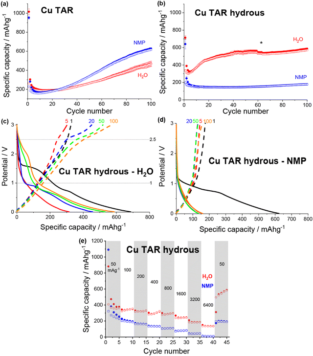 | ||
| Fig. 3 Discharge (filled) and charge (non-filled) specific capacity vs. cycle number for NMP-based (blue) and water-based (red) electrodes for (a) copper tartrate and (b) copper tartrate hydrous. Black asterisk denotes cycle where duplicate cells failed and data averaging was no longer possible. Potential vs. specific capacity curves for (c) water-based copper tartrate hydrous, and (d) NMP-based copper tartrate hydrous, for cycles 1 (black), 5 (red), 20 (blue), 50 (green) and 100 (orange). All cycling was conducted at 50 mA g−1 between 0.01 and 3 V. NMP-based copper tartrate electrode data in (a) from previous publication.23 (e) Rate capability of NMP-based (blue) and water-based (red) electrodes for copper tartrate hydrous electrodes. | ||
In all cases the initial coulombic efficiency is poor, achieving, at best, only 47% for the water-based copper tartrate hydrous electrode. There are likely several reasons for this, although two stand out as the most likely: a thick and/or unstable solid electrolyte interface (SEI) and irreversible consumption of Li by the active material. For the SEI, it is anticipated that further optimisation of the electrode formulation, especially with regards to the quantity of conductive carbon, will help to mitigate any detrimental effects by reducing the porosity and electrode cracking. Additionally, screening of various electrolyte compositions will also aid in thin/stable SEI formation. For the possible irreversible consumption of Li, deeper insight into the Li storage mechanism is required for definitive conclusions. It has been previously reported for similar materials that Li is stored initially through conversion of the MOF into lithiated forms of its component metal and ligand components (discussed in more detail below). It is possible that this process involves a step (or steps) that form irreversible lithiated side products. Ultimately, for any chance at realistic application, further studies are required to understand both of these phenomena.
The potential curves for both of the water-based electrodes are similar in shape to the previously reported NMP-based copper tartrate electrode.23 The capacity increase is again apparent in the development of the features around 1.5–2 V, and below 1 V during discharge and around 2.5 V during charge. For the water-based copper tartrate hydrous electrode (Fig. 3c), these features begin developing by cycle 20, whereas for the water-based copper tartrate electrode (Fig. 3b), they are delayed until around cycle 50. In all three electrodes, a large capacity contribution in the first discharge occurs around 1–1.5 V, that doesn’t reappear in later cycles. It is possible that this corresponds to the reported irreversible breakdown of the copper–tartrate bond, and subsequent formation of the distinct copper and tartrate species.23 No change in the potential curves with cycling occurs in the NMP-based copper tartrate hydrous electrode (Fig. 3d). Additionally, the first discharge did not display the 1–1.5 V capacity contribution, suggesting that poor specific capacity may be due to the absence of the copper–tartrate breakdown.
Further improvements imparted by the water-based formulation was evident in the rate capability of the copper tartrate hydrous electrodes (Fig. 3e). The NMP-based electrode suffered from an almost complete loss of capacity as the current rate was increased to 6400 mA g−1, whereas the water-based electrode retained ∼136 mA h g−1. If the specific capacity at cycle 5 is taken as the benchmark “stable” capacity, then the two capacity retentions were ∼4% and 38%, respectively. Upon return to 50 mA g−1, the NMP-based electrode displayed ∼200 mA h g−1 (78%), and the water-based electrode displayed ∼534 mA h g−1 (141%) with significant capacity climb to 588 mA h g−1 over the next 4 cycles.
In summary, it is clear that significantly different electrochemical performance for the same active material i.e. copper tartrate, can be achieved through electrode formulation variations. Specifically, dissolution of the active material in the slurry solvent allows for increased distribution and dispersion of the active material throughout the electrode structure, which has been demonstrated in this case to improve the electrochemical performance. Additionally, the success of the water-based electrode formulation is advantageous as it presents a greener and less toxic methodology than the more conventional NMP-based formulation.
Expanding the transition metal and acid parameter space
Based on the promising performance of the copper–acid species11,22,23 and the formulation insights gained above, a series of metal–acid species were synthesised and examined as potential Li ion anodes. The series consisted of only a very small subset of potential metal–acid species, detailed below in Table 1. The two additional metals were chosen as they are typically non-toxic, abundant, and relatively inexpensive. The three acids were chosen based on their previously reported promising performance, as well as their natural abundance, water solubility and non-toxicity. Unlike the other targets metal–acids, iron(III) tartrate was available for purchase, providing a reference compound to help in the identification of the iron–tartaric acid reaction product.Furthermore, the additional copper–acid syntheses allowed examination of the difference in electrode structure and performance, compared to the reported acid formulated electrodes,22,23 specifically the malic and maleic acid based electrodes. The acid-based formulation presents a method of improving the electrochemical performance of the electrode through microstructural optimisation. However, the improvements were also coupled with more severe capacity fade, likely due to unremoved metal–acid reaction side products. Hence, the water solubility of the metal–acids can be exploited to improve the microstructure, and pre-synthesis of the metal–acid can be used to dramatically reduce the potential for detrimental side products.
Overall, the syntheses attempted were relatively crude. Similar syntheses typically use a common salt of the metal as the precursor,11,27 which is often water soluble. Here, as with the above copper tartrate syntheses, the metal was used to continue emulating the reported in situ reaction and to aid in the recovery/purification of the water soluble metal–acid product when using a water-based extraction, i.e. the metal remains insoluble. Based on the variations in product with synthesis conditions discussed above, it is plausible that use of different precursors may result in the formation of different metal–acid analogues, especially in the case of multiple achievable redox states, e.g. Fe2+/3+. Additionally, variation of the solvent system (NMP/water ratio) had an effect on both the quantity of product formed and also the ease of product recovery. Unlike the copper tartrate reaction discussed above, only one product was isolated for each synthesis. Where complete characterisation of the species was possible, it was determined whether the product was the hydrous or anhydrous analogue. Future work will involve optimisation of these reactions, including finding the most suitable precursors and solvent systems, attempting to synthesise alternate redox states e.g. iron(II) malate, and attempting to synthesise both the hydrous and anhydrous analogues.
The copper malate (Fig. S4a, ESI†), iron malate (Fig. S5b, ESI†) and iron maleate (Fig. S5c, ESI†) were unable to be characterised by XRD, due to being either amorphous or nanocrystalline. Additionally, no crystals of adequate quality for single crystal XRD were able to be grown. However, the copper malate recrystalised during electrode formulation (discussed later) into the analogue copper D,L-malatocuprate tetrahydrate. For the iron malate and iron maleate, alternative characterisation was required.
Elemental analysis by XPS gave an approximate Fe![[thin space (1/6-em)]](https://www.rsc.org/images/entities/char_2009.gif) :
:![[thin space (1/6-em)]](https://www.rsc.org/images/entities/char_2009.gif) C
C![[thin space (1/6-em)]](https://www.rsc.org/images/entities/char_2009.gif) :
:![[thin space (1/6-em)]](https://www.rsc.org/images/entities/char_2009.gif) O ratio of 1
O ratio of 1![[thin space (1/6-em)]](https://www.rsc.org/images/entities/char_2009.gif) :
:![[thin space (1/6-em)]](https://www.rsc.org/images/entities/char_2009.gif) 6
6![[thin space (1/6-em)]](https://www.rsc.org/images/entities/char_2009.gif) :
:![[thin space (1/6-em)]](https://www.rsc.org/images/entities/char_2009.gif) 6 for the iron malate, and 1
6 for the iron malate, and 1![[thin space (1/6-em)]](https://www.rsc.org/images/entities/char_2009.gif) :
:![[thin space (1/6-em)]](https://www.rsc.org/images/entities/char_2009.gif) 7
7![[thin space (1/6-em)]](https://www.rsc.org/images/entities/char_2009.gif) :
:![[thin space (1/6-em)]](https://www.rsc.org/images/entities/char_2009.gif) 7 for the iron maleate. In both cases, the elemental ratios matched more closely to the Fe(III) species than the Fe(II) species (Table 2). Furthermore, Mössbauer spectroscopy confirmed that all of the Fe was in the Fe3+ oxidation state (Table 3 and Fig. S8c, d, ESI†) for both cases. Combined, this information suggests that the synthesised products were iron(III) malate, and iron(III) maleate. This does rely on the reasonable assumption that this reaction is proceeding in a similar fashion to the other reactions, i.e. the ligand remains unchanged.
7 for the iron maleate. In both cases, the elemental ratios matched more closely to the Fe(III) species than the Fe(II) species (Table 2). Furthermore, Mössbauer spectroscopy confirmed that all of the Fe was in the Fe3+ oxidation state (Table 3 and Fig. S8c, d, ESI†) for both cases. Combined, this information suggests that the synthesised products were iron(III) malate, and iron(III) maleate. This does rely on the reasonable assumption that this reaction is proceeding in a similar fashion to the other reactions, i.e. the ligand remains unchanged.
![[thin space (1/6-em)]](https://www.rsc.org/images/entities/char_2009.gif) :
:![[thin space (1/6-em)]](https://www.rsc.org/images/entities/char_2009.gif) C
C![[thin space (1/6-em)]](https://www.rsc.org/images/entities/char_2009.gif) :
:![[thin space (1/6-em)]](https://www.rsc.org/images/entities/char_2009.gif) O ratio measured by XPS for the synthesised iron malate and iron maleate, and the expected values for both the iron(II) and iron(III) species
O ratio measured by XPS for the synthesised iron malate and iron maleate, and the expected values for both the iron(II) and iron(III) species
| Elemental ratio | |||
|---|---|---|---|
| Fe | C | O | |
| Fe MAL | 1 | 6 | 6 |
| Theoretical Fe(II) MAL | 1 | 4 | 5 |
| Theoretical Fe(III) MAL | 1 | 6 | 7.5 |
| Fe MEC | 1 | 7 | 7 |
| Theoretical Fe(II) MEC | 1 | 4 | 4 |
| Theoretical Fe(III) MEC | 1 | 6 | 6 |
| Fe/% | Fe2+/% | Fe3+/% | |
|---|---|---|---|
| Fe(II) TAR | 5 (1) | 74 (1) | 21 (1) |
| Fe(III) TAR | — | 14 (1) | 86 (1) |
| Fe MAL | — | — | 100 (1) |
| Fe MEC | — | — | 100 (1) |
The Mössbauer analysis also revealed that the synthesised iron(II) tartrate, and the purchased iron(III) tartrate were not pure. Table 3 shows the percentage breakdown of the subspectral areas for each iron oxidation state. This is proportional to the number of Fe atoms/ions in that state, assuming that the Mössbauer recoil-free fraction is the same for all phases. For the iron(II) tartrate, the dominant iron oxidation was Fe2+ at 74%, followed by Fe3+ at 21% and Fe0 at 5%. Assuming the Fe2/3+ species are similar in composition, then the iron(II) tartrate is the major product by molar ratio. For the purchased iron(III) tartrate, only 86% of the iron was Fe3+, with the remaining 14% being Fe2+. Evidently, there is scope to improve the synthesis/purification of some of these metal–acid species.
Finally, Fourier transform infrared spectroscopy (FTIR) was conducted on each of the synthesised samples and compared to the precursor acid (Fig. S9, ESI†). As with the copper tartrate hydrous, differences were observed between each species and its precursor. Additionally, the species with the same acid moiety shared significant similarities across the spectrum of samples investigated.
All of the metal–acid species were formulated into both NMP-based and water-based electrodes. The electrode structural differences between the two formulations were assessed using SEM, XRD, SANS and USANS, and were found to vary amongst the metal–acid series. Generally, the more water soluble the metal–acid, the larger the nano and microstructural differences between the NMP and water electrode formulations, as summarised in Table 4.
| Hydrous | Water soluble | Particle size reduction (SEM) | Crystallinity difference (XRD) | Specific capacity improvement (%) | |
|---|---|---|---|---|---|
| Cu TAR hydrous | Yes | Yes | Partial | None | 330 |
| Cu MAL | Yes | Yes | Partial | Became crystalline | 500 |
| Cu MEC | Yes | No | None | Intensity ratios | 110 |
| Fe(II) TAR | No | Yes | Partial | Intensity ratios | 190 |
| Fe(III) TAR | N/A | Yes | Significant | None | 140 |
| Fe MAL | N/A | Yes | Significant | None | 190 |
| Fe MEC | N/A | Yes | Partial | None | 150 |
| Zn TAR | No | No | None | None | 260 |
| Zn MAL | Yes | Yes | Partial | Loss of crystallinity | 260 |
| Zn MEC | No | Yes | None | None | 140 |
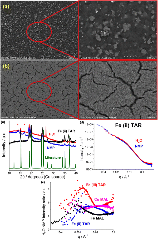
Most readily apparent was the metal–acid particle size reduction and homogenisation in the water formulations, observed using SEM. The NMP-based electrodes all contained a large number of >5 μm particles, e.g. the iron malate electrode in Fig. 4a. Similar to the previously discussed copper tartrate hydrous, many of the water-based electrodes showed significant particle size reduction, some to the point of no discrete particles being visible e.g. the iron malate electrode in Fig. 4b. Fig. S10 (ESI†) contains the electrode SEM images for all of the metal–acid series examined here. As with the copper tartrate hydrous, many of the water-based electrodes showed significantly more electrode cracking. The degree of electrode cracking is problematic for application of these materials in batteries, due to the decrease in the mechanical strength of the electrode, and overall electrochemical performance/stability. However, it must be noted that the electrode formulations used in this study are far from optimised. For initial comparison, each of the materials presented were formulated into electrodes using the same method. Further study of these materials would involve optimisation of the formulation method for specific materials, which would help mitigate the degree of electrode cracking.
XRD also revealed that for some of the metal–acid electrodes, a change in crystallinity had occurred. This is a clear indication that the different formulations can interact differently with the active material. In the case of the iron(II) tartrate (Fig. 4c), the different formulations displayed different peak intensity ratios, possibly indicating preferred growth directions depending on the solvent used. A more extreme example is the copper malate electrode, where the copper malate became crystalline after the water-based formulation, whereas it remained nanocrystalline/amorphous after the NMP-based formulation (Fig. S4a, ESI†). Fig. S4 to S6 (ESI†) contains the electrode XRD patterns for all the metal–acid series examined.
As shown in previous works,22,23 SANS and USANS are powerful tools to probe the bulk composition and structure of electrodes at a length scale of nm's to μm's. Predominantly, the insights gained using SANS and USANS are used to support bulk structural models that have been inferred from SEM-based local surface characterisation and qualify differences between the NMP-based and water-based electrodes. However, it is also anticipated that the data presented will add to the growing knowledgebase of SANS and USANS in the battery space, aiding in the future development of electrode structural models. A subset of the metal–acid electrodes was chosen for the SANS and USANS study, which focused on some of the more water soluble metal–acids, namely, iron(II) tartrate (Fig. 4d) copper malate (Fig. S11a, ESI†), iron(III) tartrate (Fig. S11b, ESI†) and iron malate (Fig. S11c, ESI†).
Comparison of the SANS and USANS data of the NMP-based and water-based electrodes demonstrated significant differences between the two formulations. In all cases, the water-based electrodes displayed higher intensity in the high to mid q region (∼6.2 nm to ∼1.6 μm), indicating a difference in the structure/composition at this length scale. Additionally, this occurred at different q ranges across the metal–acid series, indicating that the properties of the metal–acid influenced the electrode structure. This is represented in Fig. 4e which shows the SANS and USANS intensity ratio of the water-based to NMP-based electrodes. The copper malate was the only metal–acid electrode to display two distinct regions of higher intensity. In the mid to low q region (∼0.9 μm to ∼3.6 μm), the two slopes converged for all samples excluding the iron(III) tartrate, and after the convergence the NMP-based electrodes displayed higher intensities.
As SANS and USANS intensity is proportional to a number of factors it is difficult to determine definitively what these intensity differences correspond to. Based on our proposed structural model of particle size reduction and increased homogeneity, it is plausible that the intensity changes correlate in part to the redistribution of the metal–acid (I(q) ∝ concentration). At the high to mid q length scale for the water-based electrodes, the smaller particle size and greater homogenisation of the metal–acid results in higher packing density, which in turn results in higher concentration and hence higher intensity. At the low q range, the intensity will be higher for samples that contain scattering objects at that length scale or larger. Again, this is consistent with the proposed structural model. At low q, the NMP-based electrodes display the higher intensity, which corresponds to the increase in the quantity of larger metal–acid particles. As mentioned above, the iron(III) tartrate water-based electrode displays higher intensity at low q compared to the NMP-based electrode, despite having no visible large particles by SEM. It is possible that this is due to the prevalence of the large cracks in the electrode, which are dominating the scattering. If this is the case, it is further support for the application of SANS and USANS in monitoring electrode mechanical health or solid electrolyte delamination in operando.
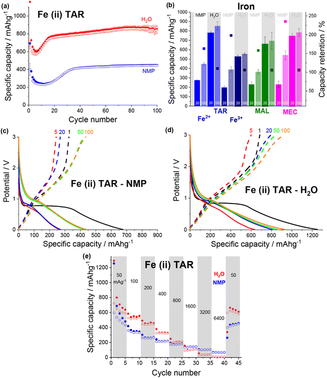
Overall, the specific capacity of the anodes varied based on both the metal–acid used and the formulation. All of the water-soluble metal–acids demonstrated higher capacities when formulated using water instead of NMP, and only the iron-based metal–acids demonstrated reasonable capacities when formulated using NMP. This demonstrates that increasing the solubility of the active material in the formulation solvent is a useful method to improve the electrochemical performance through microstructural enhancement.
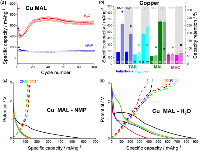 | ||
| Fig. 5 (a) Discharge (filled) and charge (non-filled) specific capacity vs. cycle number for copper malate electrodes made from an NMP (blue) and a water (red) based slurry. (b) Specific capacity at cycle 20 and 100 and capacity retention for NMP-based and water-based copper tartrate (blue), copper tartrate hydrous (cyan), copper malate (green) and copper maleate (pink) electrodes. No error bar on cycle 100 specific capacity for copper tartrate hydrous H2O based electrode due to replicate cell failure. Potential vs. specific capacity curves for NMP-based (c) and water-based (d) copper malate electrodes, for cycles 1 (black), 5 (red), 20 (blue), 50 (green) and 100 (orange). All cycling was conducted at 50 mA g−1 between 0.01 and 3 V. NMP-based copper tartrate electrode data in (b) from previous publication.23 | ||
Both copper maleate electrode formulations demonstrated poor performance, achieving only ∼140 mA h g−1 over 100 cycles (Fig. S12a, ESI†). Some capacity increase was observed for the water-based electrode, from around cycle 80 onwards, although only a small increase to ∼170 mA h g−1 was achieved by cycle 100. Previously reported maleic acid on copper electrodes have demonstrated variable performance, giving both high (∼730 mA h g−1)19,21 and low capacities (<100 mA g−1),22 although in all cases, the final electrode was not definitively confirmed to be copper maleate. Additionally, the performance difference between this study and the previously reported acid-formulated electrodes may be due to the structural differences. The acid-formulated electrodes were all composed of <1 μm copper maleate spheres, whereas both formulations reported here contain faceted particles and no spheres. Fig. 5b details a comparison of the copper–acid species examined.
The potential curves for the two copper malate electrodes are also similar to the copper tartrate hydrous electrodes, suggesting the improved microstructure “activates” the same mechanisms. The NMP-based formulation displays no change in the potential curves (Fig. 5c), which is consistent with no capacity increase. The water-based formulation has a large sloping potential feature during first discharge around 1.5 V, which is not observed in subsequent cycles (Fig. 5c). Based on the previously reported mechanism,11,23 it is possible that this feature corresponds to the breakdown process of the MOF structure. If this is the case, the absence of the feature in the NMP-based electrode suggests that the larger particle size prevents or restricts the MOF breakdown process, perhaps due to poor active material conductivity and longer Li-diffusion pathways. The capacity gain for the water-based formulation can be seen in the growth in the discharge feature around 1.5–2 V from cycle 50, and below 1 V from cycle 5, which suggests that two independent mechanisms are being “activated”, again consistent with the reported behaviour. Furthermore, the 1.5–2 V feature is not observed for the other metal–acid species (discussed below), possibly indicating that this feature corresponds to the metal-based redox mechanism i.e. Cu/CuOx. As suggested by the low, unchanging capacity, no change in the copper maleate potential profiles was observed for either electrode formulations (Fig. S12b and c, ESI†).
The first discharge of both iron(II) tartrate electrodes contained a large plateau around ∼0.9 V. Assuming the iron–acid species operate under a similar mechanism to the copper–acid species, this plateau would correspond to the MOF breakdown. Not only is this at a lower potential than the copper–acids, but it also occurs in both the NMP-based electrode (Fig. 6c) and the water-based electrode (Fig. 6d). The activation of the MOF breakdown in the NMP-based electrode helps explain why the overall cycling is far superior to the copper–acid electrodes. A similar first discharge curve was observed for all of the iron–acid species (Fig. S13, ESI†), except for iron maleate, where the feature occurred around ∼1.5 V (Fig. S13h and i, ESI†). The capacity increase (over the first 20 cycles) was only observed in the development of the <1 V regions during discharge, and this was the case for all of the iron–acids.
Comparing the rate capability of the two iron(II) tartrate electrode formulations shows that the water-based electrode has poorer rate capability (Fig. 6e), unlike the copper tartrate hydrous. As the current density is increased to 6400 mA g−1, the NMP-based and water-based electrodes drop to ∼70 mA h g−1 (14%) and ∼8 mA h g−1 (1%) respectively. Upon return to 50 mA g−1, the NMP-based and water-based electrodes deliver ∼435 mA h g−1 (90%) and ∼664 mA h g−1 (105%) respectively. It is possible that the poorer rate capability of the water-based electrode is due to structural issues such as the increased electrode cracking that is observed in the SEM images (Fig. S10f, ESI†). If this is the case, it is anticipated that better control of the electrode formulation and formation would help alleviate some of the detrimental electrode structure.30
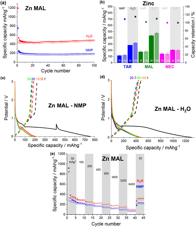
All of the zinc–acids displayed the lowest reduction potential during first discharge, with the plateau associated with the MOF breakdown occurring around 0.6 V (Fig. 7c and d). Additionally, the majority of the zinc–acids displayed quite high first discharge capacities, reaching ∼1300 mA h g−1 in the case of the water-based zinc malate (Fig. 7d). Unfortunately, much of this capacity is irreversible. It seems likely then that the initial discharge mechanism that occurs for the copper and iron species also occurs for the zinc species. Subsequently, the irreversible capacity can be explained by the zinc redox being irreversible.
Both of the zinc malate electrode formulations gave very similar rate capability performance (Fig. 7e). As the current density was increased to 6400 mA g−1, the specific capacity of the NMP-based and water-based electrodes dropped to ∼65 mA h g−1 (26%) and ∼96 mA h g−1 (30%). Upon return to 50 mA g−1, the specific capacities increased to 224 mA h g−1 (87%) and 316 mA h g−1 (96%). For the rate capability test, the water-based electrode showed a lower specific capacity compared to that shown in Fig. 7a.
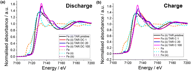
XAS of the pristine electrodes showed that the iron had a mixed oxidation state (Fig. 8), which is in agreement with the Mössbauer result. Unlike the copper systems, no Fe0 is observed upon first discharge (Fig. 8a). Instead, the iron appears to become entirely Fe3+, which is counter intuitive for Li insertion. Little change in the Fe oxidation state with subsequent discharge is observed. Upon first charge Fe3+ is also the only oxidation state observed, although a slightly different post-edge absorbance is observed, which suggests a change in the Fe local chemical environment. This is consistent with the lower capacity observed in the first charge compared to the first discharge. Subsequent charges result in the Fe post-edge more closely resembling the discharge state, in fact little difference can be seen between the discharge and charge states for cycle 20 and 100. This suggests that after the initial capacity stabilisation, the iron is not involved in the redox mechanism. Furthermore, a similar result was observed for the iron(III) tartrate electrode (Fig. S15 (ESI†) with both states of charge at cycle 20 appearing similar to the iron(II) tartrate electrode at cycle 20. Overall, it is clear that the iron tartrates operate by a different electrochemical mechanism to the copper–acids previously reported and further investigation is required to better understand the mechanism of lithium insertion.
Summary
Overall, a strong correlation between the solubility of the metal–acid, the microstructural differences between the water-based and NMP-based electrodes (represented in Fig. 9), and the electrochemical performance of these electrodes was observed (Table 4).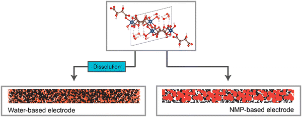 | ||
| Fig. 9 Representation of the electrode structures for the water-based and NMP-based electrodes, when made using a water-soluble active material. | ||
Specifically, the more soluble the metal–acid was in the slurry solvent, the smaller the particle size in the electrode i.e. the more homogenous the electrode on the nanoscale. Furthermore, significantly higher capacities were observed for the metal–acids that were soluble compared to those that were not, as well as all water-based electrodes giving higher capacities than the NMP-based counterparts.
When comparing the performance of the different metal–acid electrodes, it is difficult to ascertain the theoretical performance of each metal–acid due to the inability to isolate mechanical enhancement vs. chemical enhancement. The question remains, does one metal–acid give better performance than another due to increased Li uptake of a particular metal/acid (chemical enhancement), or simply due to higher solubility (resulting nano and microstructural enhancement)? This is particularly relevant when comparing metal–acids that share the same building blocks (and hence the same theoretical mechanisms) e.g. iron(II) tartrate and iron(III) tartrate – does higher Li uptake occur in the Fe-rich or Fe-poor species? Further work examining formulation optimisation, examination of a larger range of metal–acids and mechanistic studies would help to answer this question.
Conclusion
In conclusion, this study developed a deeper understanding of the use of metal-dicarboxylate MOFs as anode materials in Li ion batteries. Initially, the reaction reported between dicarboxylic acids and the copper substrate was further probed. In the case of the copper and tartaric acid reaction, it was revealed that two copper tartrate analogues were produced. The difference in solubility between the two analogues was exploited to investigate the effect of dissolution of the active material on electrode structure and subsequent electrochemical performance. This was repeated using a series of metal–acid species, which made clear the strong correlation between high active material solubility, improved electrode microstructure and high capacity. Ultimately the iron-based metal–acids e.g. iron(II) tartrate, displayed the highest capacity, reaching up to 850 mA h g−1 when formulated using a water-based electrode.Author contributions
The manuscript was written with the contributions of all authors. All authors have given approval to the final version of the manuscript.Conflicts of interest
There are no conflicts to declare.Acknowledgements
The authors acknowledge the support from the Australian Research Council (ARC) through the projects DP200100959 and FT200100707 and research training program. Additionally, we are grateful for the support from the ANSTO graduate institute. Part of this work was undertaken on the neutron beamlines at the Australian Centre for Neutron Scattering, Australian Nuclear Science and Technology Organisation (proposal ID DB9079 and P14086). Part of this work was conducted using the instruments in the Solid State Elemental Analysis Unit (SSEAU) at the University of New South Wales (UNSW) with the help of Dr Ruoming Tian and Dr Mohan Bhadbhade. Part of this research was undertaken on the MEX XAS Beamline, Australian Synchrotron, part of ANSTO.References
- M. Gutsch and J. Leker, Global warming potential of lithium-ion battery energy storage systems: A review, J. Energy Storage, 2022, 52, 105030 CrossRef.
- H. C. Hesse, M. Schimpe, D. Kucevic and A. Jossen, Lithium-Ion Battery Storage for the Grid—A Review of Stationary Battery Storage System Design Tailored for Applications in Modern Power Grids, Energies, 2017, 10(12), 2107 CrossRef.
- G. Bridge and E. Faigen, Towards the lithium-ion battery production network: Thinking beyond mineral supply chains, Energy Res. Soc. Sci., 2022, 89, 102659 CrossRef.
- T. M. Gür, Materials and technologies for energy storage: Status, challenges, and opportunities, MRS Bull., 2021, 46(12), 1153–1163 CrossRef.
- J. Asenbauer, T. Eisenmann, M. Kuenzel, A. Kazzazi, Z. Chen and D. Bresser, The success story of graphite as a lithium-ion anode material – fundamentals, remaining challenges, and recent developments including silicon (oxide) composites, Sustainable Energy Fuels, 2020, 4(11), 5387–5416 RSC.
- A. D. Jara, A. Betemariam, G. Woldetinsae and J. Y. Kim, Purification, application and current market trend of natural graphite: A review, Int. J. Min. Sci. Technol., 2019, 29(5), 671–689 CrossRef CAS.
- L. Wang, Y. Han, X. Feng, J. Zhou, P. Qi and B. Wang, Metal–organic frameworks for energy storage: Batteries and supercapacitors, Coord. Chem. Rev., 2016, 307, 361–381 CrossRef CAS.
- T. Li, Y. Bai, Y. Wang, H. Xu and H. Jin, Advances in transition-metal (Zn, Mn, Cu)-based MOFs and their derivatives for anode of lithium-ion batteries, Coord. Chem. Rev., 2020, 410, 213221 CrossRef CAS.
- M. Du, Q. Li, Y. Zhao, C.-S. Liu and H. Pang, A review of electrochemical energy storage behaviors based on pristine metal–organic frameworks and their composites, Coord. Chem. Rev., 2020, 416, 213341 CrossRef CAS.
- Z. Wu, J. Xie, Z. J. Xu, S. Zhang and Q. Zhang, Recent progress in metal–organic polymers as promising electrodes for lithium/sodium rechargeable batteries, J. Mater. Chem. A, 2019, 7(9), 4259–4290 RSC.
- X. Lou, X. Hu, S. Xiang, C. Li, Q. Yang and B. Hu, A green ligand-based copper–organic framework: a high-capacity lithium storage material and insight into its abnormal capacity-increase behavior, New J. Chem., 2020, 44(41), 17899–17905 RSC.
- X.-J. Kong and J.-R. Li, An Overview of Metal–Organic Frameworks for Green Chemical Engineering, Engineering, 2021, 7(8), 1115–1139 CrossRef CAS.
- S. Kumar, S. Jain, M. Nehra, N. Dilbaghi, G. Marrazza and K.-H. Kim, Green synthesis of metal–organic frameworks: A state-of-the-art review of potential environmental and medical applications, Coord. Chem. Rev., 2020, 420, 213407 CrossRef CAS.
- Y. Jiang, H. Zhao, L. Yue, J. Liang, T. Li, Q. Liu, Y. Luo, X. Kong, S. Lu, X. Shi, K. Zhou and X. Sun, Recent advances in lithium-based batteries using metal organic frameworks as electrode materials, Electrochem. Commun., 2021, 122, 106881 CrossRef CAS.
- R. Mehek, N. Iqbal, T. Noor, M. Z. B. Amjad, G. Ali, K. Vignarooban and M. A. Khan, Metal–organic framework based electrode materials for lithium-ion batteries: a review, RSC Adv., 2021, 11(47), 29247–29266 RSC.
- A. Morozan and F. Jaouen, Metal organic frameworks for electrochemical applications, Energy Environ. Sci., 2012, 5(11), 9269–9290 RSC.
- L. S. Xie, G. Skorupskii and M. Dincă, Electrically Conductive Metal–Organic Frameworks, Chem. Rev., 2020, 120(16), 8536–8580 CrossRef CAS PubMed.
- X. Shen, X.-Q. Zhang, F. Ding, J.-Q. Huang, R. Xu, X. Chen, C. Yan, F.-Y. Su, C.-M. Chen, X. Liu and Q. Zhang, Advanced Electrode Materials in Lithium Batteries: Retrospect and Prospect, Energy Mater. Adv., 2021, 1205324 CAS.
- Y. Wang, Y. Deng, Q. Qu, X. Zheng, J. Zhang, G. Liu, V. S. Battaglia and H. Zheng, Ultrahigh-Capacity Organic Anode with High-Rate Capability and Long Cycle Life for Lithium-Ion Batteries, ACS Energy Lett., 2017, 2(9), 2140–2148 CrossRef CAS.
- F. Xiao, P. Liu, J. Li, Y. Zhang, Y. Liu and M. Xu, A small molecule organic compound applied as an advanced anode material for lithium-ion batteries, Chem. Commun., 2022, 58(5), 697–700 RSC.
- F. Xiao, Y. Qi, H. Wang, Y. Liu, S. Bao and M. Xu, New insights into the electrochemical activity of maleic acid in lithium ion battery, Chem. Eng. J., 2022, 443, 136490 CrossRef CAS.
- M. Teusner, J. Mata and N. Sharma, In situ synthesis of Cu(II) dicarboxylate MOFs and their application as battery materials, Phys. Chem. Chem. Phys., 2023, 25(18), 12684–12693 RSC.
- M. Teusner, U. Mittal, M. Lessio, B. Johannessen, J. Mata and N. Sharma, Formulation and mechanism of copper tartrate – an anode material for lithium-ion batteries – under review, 2023.
- K. Zhang, Q. Zhao, Z. Tao and J. Chen, Composite of sulfur impregnated in porous hollow carbon spheres as the cathode of Li–S batteries with high performance, Nano Res., 2013, 6(1), 38–46 CrossRef CAS.
- C. Tian, J. Wu, Z. Ma, B. Li, X. Zhang, X. Zu, X. Xiang and S. Li, A melt-diffusion strategy for tunable sulfur loading on CC@MoS2 for lithium–sulfur batteries, Energy Rep., 2020, 6, 172–180 CrossRef.
- D. Gueon, J. T. Hwang, S. B. Yang, E. Cho, K. Sohn, D.-K. Yang and J. H. Moon, Spherical Macroporous Carbon Nanotube Particles with Ultrahigh Sulfur Loading for Lithium–Sulfur Battery Cathodes, ACS Nano, 2018, 12(1), 226–233 CrossRef CAS PubMed.
- Y.-H. Liu, S.-H. Lee, J.-C. Chiang, P.-C. Chen, P.-H. Chien and C.-I. Yang, Dehydration induced 2D-to-3D crystal-to-crystal network re-assembly and ferromagnetism tuning within two chiral copper(II)–tartrate coordination polymers, Dalton Trans., 2013, 42(48), 16857–16867 RSC.
- M. Joshi, Structural, Spectroscopic, Magnetic and Thermal Studies of GelGrown Copper Levo-Tartrate and Copper Dextro-Tartrate Crystals. IOSR, J. Appl. Phys., 2016, 8, 33 Search PubMed.
- T. Fukami and S. Tahara, Structural and Thermal Investigations of L-CuC4H4O6·3H2O and DL-CuC4H4O6·2H2O Single Crystals, Int. J. Chem., 2021, 13(1), 5 Search PubMed.
- K. Rollag, D. Juarez-Robles, Z. Du, D. L. Wood and P. P. Mukherjee, Drying Temperature and Capillarity-Driven Crack Formation in Aqueous Processing of Li-Ion Battery Electrodes, ACS Appl. Energy Mater., 2019, 2(6), 4464–4476 CrossRef CAS.
Footnote |
| † Electronic supplementary information (ESI) available. CCDC 2234180 and 2234181. For ESI and crystallographic data in CIF or other electronic format see DOI: https://doi.org/10.1039/d3ma00286a |
| This journal is © The Royal Society of Chemistry 2023 |


