 Open Access Article
Dynamic single microparticle manipulation in the far-field region using plasmonic vortex lens multiple arms with a circular groove†
Fitri
Oktafiani
 a,
Jun-Quan
Chen
 b and
Po-Tsung
Lee
 *ab
*ab
aInternational PhD Program in Photonics (IPPP), College of Electrical and Computer Engineering, University System of Taiwan (National Yang Ming Chiao Tung University), Taiwan
bDepartment of Photonics, College of Electrical and Computer Engineering, National Yang Ming Chiao Tung University, Hsinchu 300, Taiwan. E-mail: potsung@nycu.edu.tw
First published on 21st November 2022
Abstract
Recent development of particle manipulation has led to high demand for dynamic optical tweezer structures. However, confining and rotating a single microparticle in the far-field region with a uniform potential distribution remains a complicated task. A plasmonic vortex lens (PVL) has been proven to easily rotate the dielectric particle owing to its effect on orbital angular momentum (OAM). Here we propose and demonstrate PVL multiple arms with a circular groove (CG). The device consists of a multiple arm spiral slit that generates a plasmonic vortex (PV) and a circular groove to bring the PV from the surface to the far-field region. Numerical simulations are performed to calculate the intensity distribution of the primary ring, the optical force and potential. The primary ring size can be adjusted using different polarization directions. PVL 2-arms with a CG has primary ring sizes of 1082 nm under right-handed circular polarization (RCP) and 517 nm under left-handed circular polarization (LCP). Based on these primary ring sizes, a 1 μm polystyrene (PS) bead can be rotated under RCP with a minimum required power of 7.45 mW and trapped under LCP with a minimum required power of 11.84 mW. For PVL 4-arms with a CG under RCP illumination, we optimize the uniform potential distribution by carefully selecting the radius of the groove. Using a groove radius of 1050 nm, we obtain the potential difference between the smallest and largest depth along the x- and y-directions of only 70 kBT/W with a minimum required power of 14.86 mW. The method and design discussed here offer an efficient way to manipulate microparticles for micro-rotors, cell dynamic analysis, etc.
1. Introduction
The ability to trap and rotate particles has attracted much attention recently.1,2 It opens a new venue for studying the conformational change of DNA or proteins and a range of applications in microsystems such as micro-rotors, micro-blenders, and optical spanners.3,4 The first invention of optical tweezers by A. Ashkin leads to a significant impact on particle manipulation.5,6 However, conventional optical tweezers suffer from a propensity to photobleach and photodamage the particle due to the high laser power required to increase the gradient force.7–9 A polarization-shaped optical vortex trap has been used to minimize this radiation damage.7An optical vortex (OV) is associated with orbital angular momentum (OAM), which carries a helical phase eilφ (l is the topological charge and φ is the transverse azimuthal angle) with a dark spot and phase singularity at its center.10–13 For decades, OAM has been applied to many science branches, such as optical communication, quantum entanglement, non-linear optics, optical machining, and optical tweezers.14 The transfer of OAM between the OV and particle can induce a rotational motion by exerting an optical orbital torque to the micro-object.15–18 OV tweezers have been proposed to trap and rotate the particle, such as a 1D gold dimer array,19 perfect optical vortices (POVs) with two axicons,20 metallic particle trimer trapping,21 and single vortex-pair beams.22 This OV based on OAM also has been utilized to rotate various kinds of tiny objects, such as red blood cells, calcite, silica, and vaterite particles.23
Surface plasmon polaritons (SPPs) efficiently generate a high field intensity localization and break the subwavelength diffraction limit.24–27 In addition, a particle trapped by plasmonic optical tweezers (POT) and rotated by a plasmonic vortex (PV) result in a more precise position and radius of path.28,29 Based on the OV experiment, the particle positioning in the focal doughnut is required to minimalize the scattering force that can repel the particle,30 which limits the flexibility in application. Meanwhile, the dominant gradient force by a PV can overwhelm this drawback.18
Taking advantage of polarization-sensitivity of the plasmonic spiral structure, selective trapping or rotation of an isotropic dielectric particle under circular polarization has been successfully demonstrated. A three-turn Plasmonic Archimedes spiral (PAS) with a total diameter of about 11.9 μm is required to enhance the SPP field strength.31 A pair of nanocavities arranged geometrically as a right-hand Archimedes spiral also succeeded in trapping and rotating particle under linear polarization owning to its structure chirality.32 However, the generated electric fields from both structures are not uniform due to the damping effect of SPPs.33 To overcome this obstacle, we apply a plasmonic vortex lens (PVL) multiple arm spiral slit with a circular groove (CG) to levitate the microparticle in the far field and rotate it with uniform potential distribution. A PVL with a multiple arm spiral has been widely used to generate a PV due to its compactness and substantial field enhancement in an evanescent field region.34–40 The inscribed CG as a diffractor inside the PVL could bring PV away from the surface and cause the primary ring to rotate the microparticle in the far-field region. To the best of our knowledge, research about a CG inscribed in the PV tweezers for rotation in the far-field region has never been conducted. This paper analyzes the electric-field intensity distribution and trapping performance of the structures. We use PVL 2-arms with a CG to produce two different ring sizes under opposite polarization directions. After integrating the force on the surface of a 1 μm polystyrene (PS) bead along the x- and y-directions, we achieve the dynamic manipulation of the PS bead by adjusting the polarization. To observe uniform potential distribution, we carefully select the radius of the groove of PVL 4-arms with a CG and calculate the difference of potential between the smallest and largest depth along the x- and y-directions. The overall effects of polarization and geometrical parameters on the structure are comprehensively studied. Our proposed design provides dynamic microparticle manipulation with compact and highly integrated on-chip optoelectronic devices.
2. Method and design
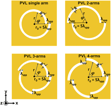
The schematics of PVL multiple arms are illustrated in Fig. 1. Each arm of the PVL is made of an Archimedes spiral slit. The spiral slit with multiple arms can be described as:37 | (1) |
When the incident light (λ = 1064 nm) with topological charge l excites the PVL structure from the back of the glass substrate, it generates a PV. This topological charge can be described as the sum of the geometrical vortex charge of the proposed plasmonic lens m and the additional angular momentum ±1 which depends on the polarization of incident light. The numerical finite element method (FEM, Comsol Multiphysics 5.3) is used to investigate the electromagnetic near field of a PVL. Fig. 2 and 3 show the simulation results of the near-field intensities of a PVL with the number m of arm segments 1, 2, 3, and 4, respectively. Under right-handed circularly polarized (RCP) illumination (l = m + 1) as shown in Fig. 2, the topological charges for structures with m = 1, 2, 3, and 4 are 2, 3, 4, and 5. As shown in Fig. 3, a PVL single arm shows a bright intensity spot at the center of the structure under left-handed circularly polarized (LCP) illumination, while the other lenses have a ring-shaped intensity distribution. The topological charges under this polarization for structures with m = 1, 2, 3, and 4 are 0, 1, 2, and 3. These results agree with the theoretical expectation of where the sign is associated with the polarization direction of incident light. It proves that the OAM per photon of an SPP vortex has increased by geometric vortex topological charge m.
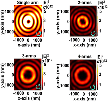 | ||
| Fig. 2 FEM simulation results of intensity distributions of various arm spiral slits under RCP illumination in the near-field region. | ||
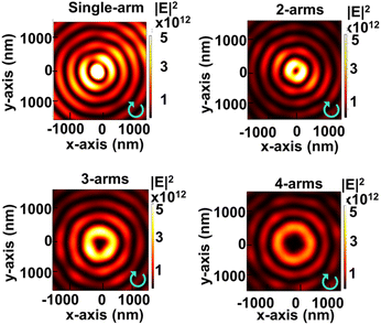 | ||
| Fig. 3 FEM simulation results of intensity distributions of various arm spiral slits under LCP illumination in the near-field region. | ||
The diameter of the ring-shaped intensity gets larger with the increased amount of topological charge, as shown in Fig. 4. However, the electric-field intensity decreases with the increase in topological charge because a PVL with a larger diameter causes more propagation loss of the SPP wave. The size of the primary ring along the x-direction under RCP is larger than that under LCP. These results have good agreement with ref. 31. The smallest ring size results from PVL 2-arms under LCP illumination (dring = 450 nm), while the largest ring size results from PVL 4-arms under RCP illumination (dring = 1624 nm), which is larger than the values reported in previous studies with dring < 1.5 μm (ref. 34) and dring = 956 nm.42 However, PVL single arm and 3-arms have non-symmetric maximum intensity distributions under RCP illumination, where the intensity on the right side of the ring is lower than that on the left side. This result shows that the geometric structure influences the symmetrical intensity distribution of the plasmonic vortex beam. Based on this, we choose PVL 2-arms and 4-arms to observe dynamic manipulation and obtain uniform potential distribution performance.
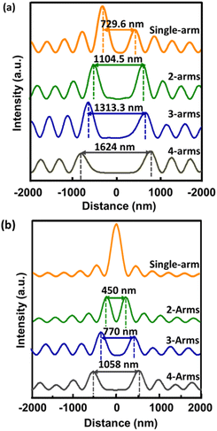 | ||
| Fig. 4 Comparison of intensity profiles and sizes of the primary ring along the x-direction under (a) RCP illumination and (b) LCP illumination. | ||
3. Results
3.1 PVL with a CG for the far-field region
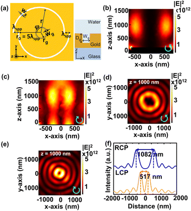
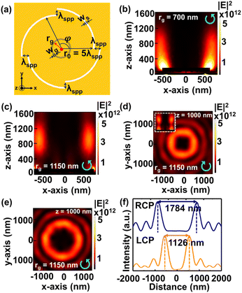
Fig. 5(a) shows the schematic of PVL 2-arms with a CG. The depth of the groove Dg is 100 nm and the groove width wg is 200 nm. After simulating several groove radii rg, we select PVL 2-arms with a CG with an rg of 800 nm, which generates the primary ring at z = 1000 nm under RCP and LCP illuminations, as shown in Fig. 5(b) and (c). Fig. 5(d) and (e) show the corresponding intensity distributions in the x–y plane at z = 1000 nm that show the generated primary rings under both polarizations. The resulting ring sizes are 1082 nm under RCP and 517 nm under LCP as shown in Fig. 5(f).For PVL 4-arms with a CG shown in Fig. 6(a), we use the same values of Dg and wg as those for PVL 2-arms with a CG. We select two groove radii that give different results under RCP illumination. When rg is determined to be 700 nm, the far-field focusing fails to be generated, as shown in Fig. 6(b). Meanwhile, PVL 4-arms with a CG with an rg of 1150 nm successfully produces the primary ring at z = 1000 nm, as shown in Fig. 6(c). These results show that the occurrence of a primary ring in the far field depends on an appropriately selected groove radius. Fig. 6(d) and (e) show the x–y plane intensity distributions under LCP and RCP polarizations at z = 1000 nm. The inset of Fig. 6(d) shows the intensity distribution in the x–z plane, proving that the far-field focusing can also be obtained in the opposite polarization direction. The primary ring sizes are 1784 nm and 1126 nm under RCP and LCP illuminations, as shown in Fig. 6(f).
3.2 PVL 2-arms with a CG for trapping and rotating particles
To demonstrate dynamic particle manipulation of PVL 2-arms with a CG, we use a 1 μm PS bead (n = 1.59) and mount the device in a water environment (n = 1.33). The gradient force can be obtained by integrating the Maxwell stress tensor (MST, TM) on the external surface of the PS bead, as defined by using the following equation: | (2) |
 | (3) |
![[n with combining circumflex]](https://www.rsc.org/images/entities/i_char_006e_0302.gif) is the unit vector perpendicular to the integration surface. The optical potential U is obtained by integrating the force on the PS bead surface along different directions:
is the unit vector perpendicular to the integration surface. The optical potential U is obtained by integrating the force on the PS bead surface along different directions: | (4) |
Fig. 7(a) and (b) show that the PS bead is dragged by the optical forces (Fx, Fy) into the primary ring region and rotated in an anti-counter-clockwise direction under RCP illumination. The diameter of the particle rotation path is 700 nm with the deepest potentials of Ux = 1513 kBT/W and Uy = 1342 kBT/W as indicated by the blue dashed line, meaning the required minimum power for stable rotation is 7.45 mW, where kB is the Boltzman constant and T is the temperature. However, this optical rotation does not occur under LCP illumination. In Fig. 8(a) and (b), the deepest potentials occur around x = 0 and y = −200 and 300 nm with Ux = 3580 kBT/W and Uy = 844 and 912 kBT/W. This indicates that under LCP illumination the particle will be trapped rather than rotated because the primary ring size is smaller than the diameter of the PS bead, and the minimum required trapping power is 11.84 mW. Switching the polarization direction can realize different optical manipulation behaviors for PVL 2-arms with a CG. The particle with a diameter of 1 μm will be rotated under RCP illumination and trapped under LCP illumination.
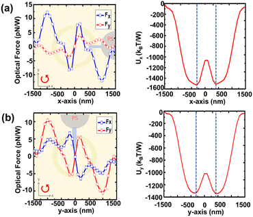 | ||
| Fig. 7 Calculated optical performances of PVL 2-arms with a CG using a 1 μm PS bead. Rotating force (Fx, Fy) and rotating potential U along the (a) x-axis and (b) y-axis under RCP illumination. | ||
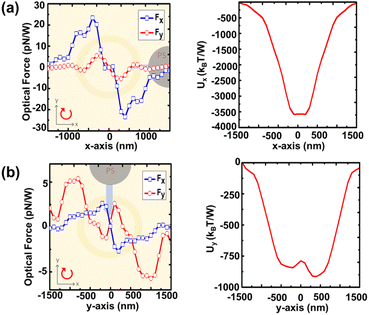 | ||
| Fig. 8 Calculated optical performances of PVL 2-arms with a CG using a 1 μm PS bead. Rotating force (Fx, Fy) and rotating potential U along the (a) x-axis and (b) y-axis under LCP illumination. | ||
3.3 PVL 4-arms with a CG for rotating the particle with a uniform potential distribution under RCP illumination
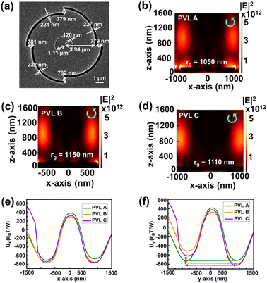
To observe the uniform potential distribution of the primary ring for particle rotation under RCP illumination, we simulate PVL 4-arms with a CG with different parameters. PVL A has an rg of 1050 nm and PVL B has an rg of 1150 nm with the same r0, ws, and wg of 3940, 200, and 200 nm. Parameters of PVL C are obtained from the SEM image of the fabricated structure. After milling by using a focus ion beam (FIB), the actual r0, wg, and rg of PVL C are 3940, 120, and 1110 nm with different slit widths for each arm, as shown in Fig. 9(a). The structure is compact and 10.24 μm in diameter.Fig. 9(b)–(d) show the intensity distributions in the x–z plane under RCP illumination and Fig. 9(e) and (f) show the optical potentials along the x-axis and y-axis for PVL A, B, and C. PVL A has a more uniform potential distribution compared to the others. The difference between the smallest and largest depths is only 70 kBT/W. Meanwhile, PVL B and PVL C have larger differences of 285 and 204 kBT/W, respectively. In addition, we can reduce the minimum required power from 19.45 mW (PVL B) to 14.86 mW (PVL A). For conventional optical tweezers, this power would increase the temperature of the system and may lead to the photodamage of particles.8 However, OV has been proven to have a less damaging effect because the laser energy is spatially more dispersed. For example, under a laser beam power of 75 mW, the mitochondria (stained with Mitotracker green dye) trapped by conventional optical tweezers show the photobleaching phenomenon more rapidly than that trapped by the vortex trap. Moreover, the mitochondria trapped by OV has a stable fluorescent signal.7 These suggest that our minimum required power would not significantly cause photodamage. Compared to the PAS structure,31 our proposed design has lower required minimum power for rotating the particle and a more compact size. This PAS structure also has a non-uniform potential distribution along the particle rotation path. However, PAS successfully stably traps and rotates a 1 μm PS bead experimentally with optical powers ranging from 40 to 80 mW despite the non-uniform potential distribution from simulation. Based on this, we also conducted the rotation experiment using PVL C.
We put the sample in a homemade chamber containing PDMS, glasses, and cover glass. The mixed solution of 0.002% 1 μm PS bead and 1% surfactant is added into the chamber. Fig. 10(a) shows an optical manipulation laser system. A 1064 nm near-infrared laser beam with x-polarization passes through the collimator and is converted to RCP illumination by using a quarter-wave plate. Then the beam is reflected by using a mirror and focused by using a 20× objective lens before hitting the backside of the sample.
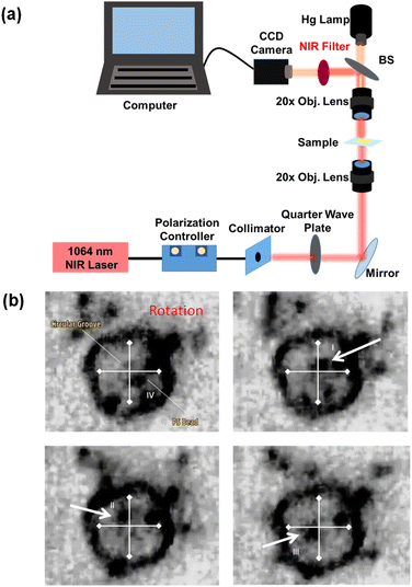 | ||
| Fig. 10 (a) Illustration of an optical manipulation laser system. (b) Images of particle rotation using a PVL C under RCP illumination extracted from ESI Sections.† The particle indicated by the white arrow rotates in the anti-clockwise direction. | ||
A CCD camera connected to a computer and a Halogen lamp through a 20× objective lens are used to record the motion of the PS bead. As shown in Fig. 10(b), a PS bead is successfully rotated in the anti-clockwise direction via observation from the four quadrants indicated by the cross sign. The particle sequentially moves from the fourth, first, second, and third quadrants. The images are extracted from the video (ESI Section†). Compared to the symmetric plasmonic lens, such as holographic plasmonic tweezers and a 3D nanotip,43,44 the alignment between the singularity of the beam and the precise center of the Archimedes spiral structure is not required.45 Our design offers an easy way to rotate micro-particles and a more compact structure for experimental realization.
4. Conclusion
We present PVL multiple arms with a CG to generate a PV in the far-field region. The radius of the CG is designed to bring the PV from the surface to the far field with uniform potential distribution. Switching the polarization direction can generate different sizes of the primary ring, which can be used for dynamic optical manipulation. For PVL 2-arms with a CG, the primary ring size can be adjusted to 1082 nm under RCP illumination and 517 nm under LCP illumination. We evaluate the optical manipulation performance using a 1 μm PS bead. Optical rotation occurs under RCP illumination with the minimum required power of 7.45 mW. Meanwhile, optical trapping under LCP illumination is obtained with the minimum required power of 11.84 mW. We carefully select the groove radius of PVL 4-arms with a CG to achieve a uniform potential distribution. PVL 4-arms with a CG with a groove radius rg of 1050 nm has the lowest potential difference between the smallest and largest depth along the x- and y-directions, which is 70 kBT/W with the minimum required rotating power of 14.86 mW. Our approach offers an easy way to study DNA and protein characteristics and is easy to apply to the lab-on-chip field.Author contributions
F. Oktafiani and J.-Q. Chen were in charge of the numerical simulations, experiment and analysis under the supervision of P.-T. Lee; F. Oktafiani prepared the original manuscript and P.-T. Lee has given approval to the final version of the manuscript.Conflicts of interest
The authors declare no conflicts of interest.Acknowledgements
The authors acknowledge the financial support from the Ministry of Education (MOE) in Taiwan. This work was supported by the National Science and Technology Council (NSTC) in Taiwan under contract numbers NSTC 109-2221-E-009-148-MY2 & NSTC 111-2221-E-A49-018-MY3 and Academia Sinica in Taiwan under contract number iMATE project AS-iMATE-111-41. The authors also thank the Center for Nano Science and Technology in National Yang Ming Chiao Tung University for its assistance with fabrication.References
- G. D. Bruce, P. Rodríguez-Sevilla and K. Dholakia, Adv. Phys.: X, 2021, 6, 1838322 Search PubMed.
- Y. Shen, X. Wang, Z. Xie, C. Min, X. Fu, Q. Liu, M. Gong and X. Yuan, Light: Sci. Appl., 2019, 8, 1–29 CrossRef CAS PubMed.
- A. T. O'Neil and M. J. Padgett, Opt. Commun., 2000, 185, 139–143 CrossRef.
- N. Simpson, K. Dholakia, L. Allen and M. Padgett, Opt. Lett., 1997, 22, 52–54 Search PubMed.
- A. Ashkin, Phys. Rev. Lett., 1970, 24, 156 Search PubMed.
- A. Ashkin, J. M. Dziedzic and T. Yamane, Nature, 1987, 330, 769–771 CrossRef CAS PubMed.
- G. D. M. Jeffries, J. S. Edgar, Y. Zhao, J. P. Shelby, C. Fong and D. T. Chiu, Nano Lett., 2007, 7, 415–420 CrossRef CAS PubMed.
- A. Blázquez-Castro, Micromachines, 2019, 10, 507 Search PubMed.
- E. J. Peterman, F. Gittes and C. F. Schmidt, Biophys. J., 2003, 84, 1308–1316 CrossRef CAS PubMed.
- L. Allen, M. W. Beijersbergen, R. Spreeuw and J. Woerdman, Phys. Rev. A, 1992, 45, 8185 CrossRef PubMed.
- Y. Gorodetski, A. Drezet, C. Genet and T. W. Ebbesen, Phys. Rev. Lett., 2013, 110, 203906 Search PubMed.
- J. Courtial, K. Dholakia, L. Allen and M. Padgett, Opt. Commun., 1997, 144, 210–213 CrossRef CAS.
- A. E. Willner, H. Huang, Y. Yan, Y. Ren, N. Ahmed, G. Xie, C. Bao, L. Li, Y. Cao and Z. Zhao, et al. , Adv. Opt. Photonics, 2015, 7, 66–106 Search PubMed.
- Y. Shen, X. Wang, Z. Xie, C. Min, X. Fu, Q. Liu, M. Gong and X. Yuan, Light: Sci. Appl., 2019, 8, 90 CrossRef PubMed.
- V. Garcés-Chávez, K. Volke-Sepulveda, S. Chávez-Cerda, W. Sibbett and K. Dholakia, Phys. Rev. A, 2002, 66, 063402 CrossRef.
- H. He, M. Friese, N. Heckenberg and H. Rubinsztein-Dunlop, Phys. Rev. Lett., 1995, 75, 826 CrossRef CAS PubMed.
- M. Friese, J. Enger, H. Rubinsztein-Dunlop and N. R. Hecken-berg, Phys. Rev. A, 1996, 54, 1593 CrossRef CAS PubMed.
- L. Zhang and P. L. Marston, Phys. Rev. E: Stat., Nonlinear, Soft Matter Phys., 2011, 84, 065601 CrossRef PubMed.
- J.-W. Liaw, C.-W. Chien, K.-C. Liu, Y.-C. Ku and M.-K. Kuo, Sci. Rep., 2018, 8, 1–8 Search PubMed.
- X. Wang, Y. Zhang, Y. Dai, C. Min and X. Yuan, Photonics Res., 2018, 6, 847–852 CrossRef CAS.
- Z. Shen, L. Su, X.-C. Yuan and Y.-C. Shen, Appl. Phys. Lett., 2016, 109, 241901 CrossRef.
- J. Wen, B. Gao, G. Zhu, D. Liu and L.-G. Wang, Opt Laser. Eng., 2022, 148, 106773 CrossRef.
- M. Padgett and R. Bowman, Nat. Photonics, 2011, 5, 343–348 CrossRef CAS.
- H. Yang, J. Li and G. Xiao, AIP Adv., 2014, 4, 127114 CrossRef.
- W. L. Barnes, A. Dereux and T. W. Ebbesen, Nature, 2003, 424, 824–830 Search PubMed.
- D. K. Gramotnev and S. I. Bozhevolnyi, Nat. Photonics, 2010, 4, 83–91 CrossRef CAS.
- E. Economou, Phys. Rev., 1969, 182, 539 CrossRef.
- J. Huang and Y. Yang, Nanomaterials, 2015, 5, 1048–1065 CrossRef CAS PubMed.
- Y. Zhang, W. Shi, Z. Shen, Z. Man, C. Min, J. Shen, S. Zhu, H. P. Urbach and X. Yuan, Sci. Rep., 2015, 5, 1–9 Search PubMed.
- Z. Shen, Z. Hu, G. Yuan, C. Min, H. Fang and X.-C. Yuan, Opt. Lett., 2012, 37, 4627–4629 Search PubMed.
- W.-Y. Tsai, J.-S. Huang and C.-B. Huang, Nano Lett., 2014, 14, 547–552 Search PubMed.
- Y. Yang and S. Huang, Nanomater. Nanotechnol., 2021, 11, 1–7 Search PubMed.
- J. Fang, C. Zhou, Z. Mou, S. Wang, J. Yu, Y. Yang, G. J. Gbur, S. Teng and Y. Cai, New J. Phys., 2021, 23, 033013 Search PubMed.
- H. Kim, J. Park, S.-W. Cho, S.-Y. Lee, M. Kang and B. Lee, Nano Lett., 2010, 10, 529–536 CrossRef CAS PubMed.
- B. Tang, B. Zhang and J. Ding, Appl. Opt., 2019, 58, 833–840 CrossRef PubMed.
- Y. Yang, L. Wu, Y. Liu, D. Xie, Z. Jin, J. Li, G. Hu and C.-W. Qiu, Nano Lett., 2020, 20, 6774–6779 Search PubMed.
- C. D. Zhou, Z. Mou, R. Bao, Z. Li and S.-Y. Teng, Front. Phys., 2021, 16, 1–8 Search PubMed.
- R. Kerber, J. Fitzgerald, X. Xiao, S. S. Oh, S. Maier, V. Giannini and D. Reiter, New J. Phys., 2018, 20, 095005 CrossRef.
- F. Huang, X. Jiang, H. Yuan and X. Sun, Plasmonics, 2017, 12, 751–757 CrossRef CAS.
- S.-W. Moon, H.-D. Jeong, S. Lee, B. Lee, Y.-S. Ryu and S.-Y. Lee, Opt. Express, 2019, 27, 19119–19129 CrossRef CAS PubMed.
- A. D. Rakíc, A. B. Djurišíc, J. M. Elazar and M. L. Majewski, Appl. Opt., 1998, 37, 5271–5283 Search PubMed.
- Q. Jiang, Y. Bao, J. Li, L. Tian, T. Cui, L. Sun, B. Du, B. Li, B. Bai and J. Wang, et al. , Photonics Res., 2020, 8, 986–994 Search PubMed.
- P. R. Huft, J. D. Kolbow, J. T. Thweatt and N. C. Lindquist, Nano Lett., 2017, 17, 7920–7925 CrossRef CAS PubMed.
- K. Liu, N. Maccaferri, Y. Shen, X. Li, R. P. Zaccaria, X. Zhang, Y. Gorodetski and D. Garoli, Opt. Lett., 2020, 45, 823–826 CrossRef PubMed.
- W. Chen, D. C. Abeysinghe, R. L. Nelson and Q. Zhan, Nano Lett., 2010, 10, 2075–2079 Search PubMed.
Footnote |
| † Electronic supplementary information (ESI) available: Short movie showing the rotation of a 1 μm PS bead by using PVL 4-arms with a circular groove (movie_1.MP4). See DOI: https://doi.org/10.1039/d2na00670g |
| This journal is © The Royal Society of Chemistry 2023 |

