 Open Access Article
A multifunctional integrated carbon nanotubes/polyphenylene sulfide composite: preparation, properties and applications†
Lingpu
Jia
 *a,
Juan
Hao
b,
Qingliang
Feng
 c,
Huiming
Li
d and
Kunping
Liu
 *b
*b
aKey Laboratory of Medicinal and Edible Plants Resources Development of Sichuan Education Department, Institute for Advanced Study, Chengdu University, Chengdu 610106, China. E-mail: jialingpu@cdu.edu.cn
bKey Laboratory of Medicinal and Edible Plants Resources Development of Sichuan Education Department, Sichuan Industrial Institute of Antibiotics, School of Pharmacy, Chengdu University, Chengdu 610106, China. E-mail: liukunping@cdu.edu.cn
cKey Laboratory of Special Functional and Smart Polymer Materials of Ministry of Industry and Information Technology, School of Chemistry and Chemical Engineering, Northwestern Polytechnical University, Xi'an 710072, Shaanxi, China
dSchool of Food and Biological Engineering, Chengdu University, Chengdu 610106, China
First published on 15th February 2023
Abstract
Although great progress has been achieved in polyphenylene sulfide (PPS) composites by the use of carbon nanotubes (CNTs), the development of cost-efficient, well dispersive and multifunctional integrated PPS composites has yet to be achieved because of the strong solvent resistance of PPS. In this work, a CNTs-PPS/PVA composite material has been prepared by mucus dispersion-annealing, which employed polyvinyl alcohol (PVA) to disperse PPS particles and CNTs at room temperature. Dispersion and scanning electron microscopy observations revealed that PVA mucus can uniformly suspend and disperse micron-sized PPS particles, promoting the interpenetration of the micro–nano scale between PPS and CNTs. During the annealing process, PPS particles deformed and then crosslinked with CNTs and PVA to form a CNTs-PPS/PVA composite. The as-prepared CNTs-PPS/PVA composite possesses outstanding versatility, including excellent heat stability with resistant temperatures up to 350 °C, corrosion resistance against strong acids and alkalis for up to 30 days, and distinguished electrical conductivity with 2941 S m−1. Besides, a well-dispersed CNTs-PPS/PVA suspension could be used to 3D print microcircuits. Hence, such multifunctional integrated composites will be highly promising in the future of new materials. This research also develops a simple and meaningful method to construct composites for solvent resistant polymers.
Introduction
High-performance polymer composites have become indispensable strategic materials in the fields of national defence and economic construction because of their excellent comprehensive properties, which have been widely applied in aerospace, wind power generation, rail transportation, automobiles and other fields.1–3 Polyphenylene sulfide (PPS), as one of the six special functional engineering materials, possesses more outstanding advantages including high temperature resistance, radiation resistance, corrosion resistance, mechanical properties, flame retardant properties and biocompatibility.4,5 Furthermore, carbon nanocomposites based on PPS have demonstrated their potential as high-performance and multifunctional materials, especially in high temperature and corrosive environments.6Materials that are commonly used to modify PPS include graphene,7 carbon nanotubes,8 fullerene, carbon fiber,9 boron nitride10 and others,11 and they can effectively enhance the mechanical behaviour and electrical and thermal conductivity properties of PPS.12 In their research studies, common synthesis methods are the hot-compression method,13 the melt blending method,14 and solid mixed-melt injection molding,15 and there is almost no solution mixing method for strong solvent resistance of PPS. But for the preparation of composite materials, the dispersion of composites prepared by the solution mixing method is much better than melt mixing and solid mixing, so researchers have been trying to prepare PPS composites by the solution blending method which has advantages in terms of dispersion, temperature, equipment.
In research of 100 years ago, Einstein has concluded the well-known viscosity model based on a hydro-dynamic theory for diluted and concentrated dispersions of various solutes and particles,16,17 and relevant studies show that nanoparticles exhibit great dispersibility in viscous fluids.18,19 The PPS reagent that we can obtain generally exists in the form of granules (about 1–5 mm) and powders (about 1–5 μm). As an extension of Einstein's hydrodynamic viscosity model,20,21 PPS particles and nanomaterials may be evenly dispersed in mucus, which is beneficial for the synthesis of uniform composite materials. In general, the particle dispersion stability is mainly determined by the inter-particle interactions between the solvent and particle surface. But when the particle size is too large (micron grade or more), a force must be provided to prevent settlement against gravity, which requires solution to have a certain viscosity.22 Polyvinyl alcohol (PVA), which is a well known water-soluble polymer, is a good film-forming agent with strong viscosity.23,24 So far, it has been widely used in spinning, printing, papermaking, pharmaceutical manufacturing and so on.25,26 Furthermore, related research studies manifest that PVA solution can prevent nano-particles from gathering together.27
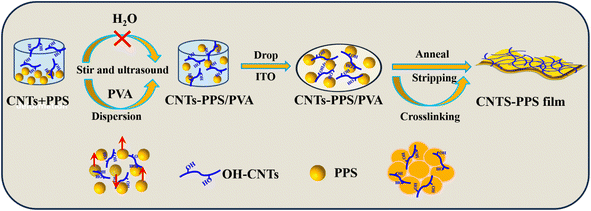
With all that said, the mucus dispersion-annealing method was proposed for the first time to prepare a CNTs-PPS/PVA composite in this work. Hydroxyl multi-walled carbon nanotubes (CNTs) are a good kind of conductive material with excellent mechanical properties, which can effectively enhance the conductivity and mechanical properties of PPS.28 PVA mucus as solvent suspended PPS particles by controlling viscosity and dispersed CNTs by virtue of abundant hydroxyl. Due to the thermoplasticity of PPS, it would melt and crosslink with CNTs to form a stable CNTs-PPS/PVA composite in the annealing process. Dispersion observations reveal that CNTs still could be uniformly distributed in the PPS composite when the doping amount is up to 33%. Furthermore, as a multifunctional integrated composite, CNTs-PPS/PVA exhibits excellent reliable mechanical properties, excellent thermostability, corrosion resistance and electrical conductivity. These results indicate that the mucus dispersion-annealing method improves the comprehensive performance of CNTs-PPS/PVA; meanwhile, it offers an environmentally friendly way to recombine insoluble substances with others.
Materials and methods
Materials
Hydroxyl multiwalled carbon nanotubes (CNTs, 95%) were purchased from XFNANO company (Nanjing, China) and polyphenylene sulfide (PPS, 99%) was obtained from Sigma-Aldrich. Polyvinyl alcohol (PVA-1788, 98%) came from Chengdu Cologne Chemicals Co., Ltd (Chengdu, China).Instrumentation
The surface morphologies were observed through a field-emission scanning electron microscope (FE-SEM) (Ultra 55, Germany). Fourier transformation infrared spectroscopy (FT-IR) data were analysed using a FT-IR spectrometer (Spectrum one, America). Conductivity data and tensile strength came from a digital four-probe tester (ST2253, China) and microcomputer controlled electronic universal testing machine (C42.503Y MTS, America), respectively. X-ray diffraction (XRD) (X'pert PRO, Netherlands) was used to study crystalline structures. The thermal analysis-infrared (TG-IR) data was obtained by thermal analysis-infrared-gas chromatography-mass spectrometry (STA449F5- INVENIO R, Germany). The size distribution of PPS particles can be measured using a laser particle analyser (90 Plus, Germany). All electrochemical experiments were carried out on a CHI 630E workstation (CH Instrument, America) with a three-electrode system, in which CNTs-PPS/PVA acts as the working electrode, and standard calomel electrode Hg/HgCl2 and a platinum wire play the roles of the reference and the auxiliary electrode, respectively. The printed microcircuit diagram of CNTs-PPS/PVA was obtained using a microelectronic printer (Scientific 3, Prtronic, Shanghai Mifang Technology, China).Synthesis of the CNTs-PPS/PVA composite material
PVA pellets (1.60 g) were added to deionized water (20 mL) and stirred at 90 °C until completely dissolved (0.08 g mL−1). Other concentrations of PVA were formulated in the same way. After cooling, the above PVA solution (2.00 mL) was taken into a glass bottle. Subsequently, PPS (0.10 g) and CNTs (0.05 g) were added into the glass bottle, sonicated and stirred for 48 h. Finally, the uniform suspension of CNTs-PPS/PVA was dripped on the surface of the indium tin oxide (ITO) glassy electrode, sintered for 3 h at 300 °C and denoted as 33% CNTs-PPS/PVA, as shown in Scheme 1. The other mass ratios of CNTs/PPS (wt%: 0%, 5%, 10%, 20%, and 25%) were also obtained by the same method. In order to strip the CNTs-PPS/PVA composite film from ITO, the sample was further immersed in 4 M KOH solution and then dried at 60 °C after being washed with deionized water.Results and discussion
The dispersion of PPS in solvents
In order to investigate the dispersion of PPS particles in ordinary solution, PPS particles were scattered in H2O, ethanol, 1-methyl-2-pyrrolidinone (NMP), dimethyl formamide (DMF) and PVA mucus, respectively. After being sonicated for 3 h, PPS particles (0.05 g) can be temporarily suspended in 4.0 mL solvents (Fig. 1a). Half an hour goes by, and they visibly start to sediment at the bottom of the bottle in other solvents except in PVA mucus (Fig. 1b). Meanwhile, it should be noticed that the 0.01 g mL−1 PVA solution has a clear separation after 12 h (Fig. 1c) and 0.10 g mL−1 PVA mucus can persist for 7 days (Fig. 1d–f). These phenomena indicate that PPS particles are insoluble in any of the above solutions and PVA mucus can effectively suspend PPS particles for a long time at higher concentrations because of its greater viscosity. The viscosity values of related solvents are listed in Table 1. Except that PVA spans from 3 to 3600 mPa s with the concentrations increasing from 0.01 to 0.16 g mL−1, the other solutions are all lower than 2 mPa s. Such a wide viscosity range would facilitate the dispersion of irregular PPS particles; therefore, the effect of PVA viscosity on PPS dispersity has been further studied. | ||
| Fig. 1 Dispersion study of PPS particles in H2O, ethanol, NMP, DMF, and PVA (0.01 and 0.10 g mL−1) for (a) 0 h, (b) 0.5 h, (c) 12 h, (d) 24 h, (e) 72 h, and (f) 168 h. | ||
| Solvent | H2O | Ethanol | NMP | DMF | PVA (g mL−1) | |||||
|---|---|---|---|---|---|---|---|---|---|---|
| 0.01 | 0.05 | 0.08 | 0.10 | 0.12 | 0.16 | |||||
| Viscosity (mPa s) | 0.89 ± 0.04 | 1.1 ± 0.02 | 1.6 ± 0.09 | 0.8 ± 0.03 | 3.3 ± 0.2 | 33 ± 2.3 | 172 ± 12 | 501 ± 26 | 1178 ± 87 | 3600 ± 165 |
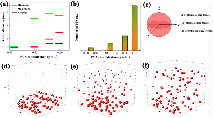
The dispersion of PPS particles in the supernatants was investigated using a laser particle size analyser (LDPSA) and SEM, which were derived from PVA solutions with different concentrations after 12 h of rest (Fig. S1a†). As can be seen from Fig. 2a, when the concentration of PVA is 0.01 g mL−1, only small PPS particles (d < 2 μm) can be captured. Once the concentration of PVA reaches 0.05 g mL−1, particles of 10 μm will appear. Meanwhile, the mean diameters and dispersion numbers of PPS particles gradually increase from 0.01 to 0.10 g mL−1, which are also confirmed by SEM as shown in Fig. S1(b–f).† The mean diameters of PPS are 1.3, 1.7, 3.8 and 5.8 μm, respectively. What's even more remarkable is that the suspension amount of PPS particles increases dramatically when the concentration of PVA is greater than or equal to 0.08 g mL−1, indicating that most PPS particles can stably exist in the solution (Fig. 2b) and can be used for subsequent research.
The key to suspending and dispersing PPS particles is the viscosity of PVA. In the PVA mucus, the main forces that suspend PPS particles include micro forces (intermolecular forces, hydrogen bonds and conjugate action) and macro forces (gravity, floatage and friction). In the quiescent state, the vector sum of micro forces can achieve balance in all spatial directions; hence the PPS particle suspension balance is controlled by macro forces in the z direction (Fig. 2c). In water, a very low viscosity (0.89 mPa s) can't overcome the gravity of PPS to suspend, leading to sedimentation at the bottom of water (Fig. 2d). As the concentration of PVA solution increases to 0.01 g mL−1 (3.3 mPa s), only the smaller particles were suspended and dispersed in the three-dimensional system (Fig. 2e), so the average particle size of PPS detected is low (1.3 μm, matched with Fig. 2a). Until the concentration of PVA reached 0.08 g mL−1 or higher, the sum of floatage and friction provided by PVA mucus drew a near gravity value, and an increase in the number of PPS particles was obtained (Fig. 2f). Hence, the PVA concentration for subsequent dispersion experiments should be at least 0.08 g mL−1. The above mutually confirmed results also illustrate that PVA mucus can stably suspend and disperse PPS particles by controlling its concentration.
The dispersion of PPS in CNTs/PVA
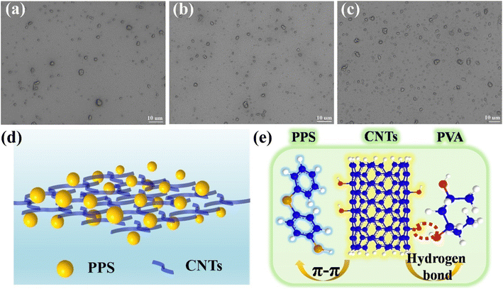
For a single dispersed system, the dispersion of particles is mainly controlled by the intrinsic viscosity of the liquid, whereas in a heterogeneous dispersion system, the interaction between particles must affect dispersion behaviour; therefore the effect of CNT content on PVA collaborative decentralized PPS particles was further investigated. As shown in Fig. 3a–c, the amount of PPS particles in the dispersion system increases gradually with CNTs increasing from 5–33% in 0.08 g mL−1 PVA solution. Meanwhile, when the doping amount of CNTs is up to 33%, there is no obvious agglomeration of PPS particles, revealing that CNTs can synergistically suspend and disperse PPS particles. The dispersal pattern of CNTs and PPS in PVA is shown in Fig. 3d. From the point of view of macroscopic mechanics, the CNTs must increase the viscosity of the polyphase dispersing system according to Einstein's viscosity model.18| μeff = μf(1 + 25φ) | (1) |
The annealing process of the CNTs-PPS/PVA composite
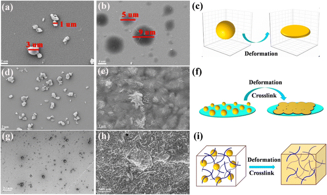
The thermal deformation and crosslink behaviours of PPS particles were investigated by comparing them before and after calcination. Fig. 4a displays the morphology of separate PPS particles that were dispersed by ultrasonic treatment with ultrapure water. After being annealed at 300 °C for 3 h, the separate PPS particles deformed and enlarged within a certain range (Fig. 4b), which provides a basis for the recombination of PPS and CNTs. Fig. 4c exhibits the three-dimensional deformation process of a single PPS particle. However, when the distribution density of PPS particles is enough, these particles not only deform but also cross-link with each other, as displayed in Fig. 4d–f. Therefore, for the composite system in this study, the PPS particles and CNTs crosslinked with each other to form a uniform CNTs-PPS/PVA composite during the annealing (Fig. 4g), and a phenomenon where the CNTs were evenly distributed in the composite can be obtained as shown in Fig. 4h. In the process of cross-linking, the key to maintaining the dispersity of CNTs-PPS/PVA is that only PPS deforms in the micron range at high temperature, so the as-prepared system still maintains a solid state and doesn't change the dispersion of the CNTs-PPS/PVA system (Fig. 4i).Structure and morphology analysis of CNTs-PPS/PVA
A picture of the CNTs-PPS/PVA film with 1 × 1 cm2 is shown in Fig. S2,† and the annealed CNTs-PPS/PVA composite tightly attaches to the surface of ITO. After being soaked in 4 M KOH, the CNTs-PPS/PVA composite was completely separated from the ITO substrate and a flexible film was obtained that can curl at 180°. The morphology of the CNTs-PPS/PVA film was investigated by SEM, and CNTs uniformly disperse in PPS with a high concentration (wt 33%), as can be seen from Fig. 5a–c. Meanwhile, energy dispersive spectroscopy of CNTs-PPS/PVA confirms the existence of C, S and O elements (Fig. S3†). Fig. 5d–f reveal the morphology of cross-sections with a thickness of 12 μm (Fig. S4†). In addition to uniformly dispersed structures, there is some undoped PPS on account of which CNTs cannot fully penetrate into larger sized particles. Besides, elemental mapping images composed of C, S, and O also prove an excellent dispersion (Fig. 5g–i) in the cross-section, which further illustrates that the mucus dispersion-annealing method successfully constructs a uniform CNTs-PPS/PVA composite.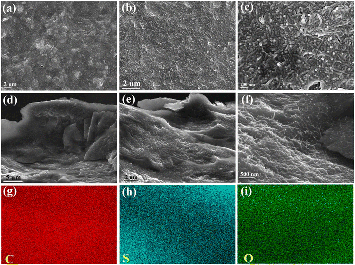 | ||
| Fig. 5 SEM images of 33% CNTs-PPS/PVA (a–c), cross-sections (d–f) and elemental mapping images (g–i). | ||
The structure and compositional changes of the CNTs-PPS/PVA film were characterized by FT-IR spectroscopy. Fig. 6a shows the curves of pure PVA before and after annealing. It can be found that the peaks at 3300–3500 cm−1 (–OH) and 1364 cm−1 (–CH2–) almost disappear and the stretching vibrations of –CH![[double bond, length as m-dash]](https://www.rsc.org/images/entities/char_e001.gif) C– (1593, 1716 cm−1) have blue shifted after annealing, illustrating that PVA is dehydrated and has become a double bond chain structure.30Fig. 6b reveals that the peaks of PPS, PVA and CNTs at 3300–3400 cm−1 get weakened after annealing as displayed in the curve of CNTs-PPS/PVA, which is because PVA and CNTs dehydrate. The peaks at 1571 and 1641 cm−1 are regarded as stretching vibrations of C
C– (1593, 1716 cm−1) have blue shifted after annealing, illustrating that PVA is dehydrated and has become a double bond chain structure.30Fig. 6b reveals that the peaks of PPS, PVA and CNTs at 3300–3400 cm−1 get weakened after annealing as displayed in the curve of CNTs-PPS/PVA, which is because PVA and CNTs dehydrate. The peaks at 1571 and 1641 cm−1 are regarded as stretching vibrations of C![[double bond, length as m-dash]](https://www.rsc.org/images/entities/char_e001.gif) C, which have shifted compared to those of PVA, CNTs and PPS.31,32 The stretching vibrations of the benzene ring in PPS are located at 1467 and 1383 cm−1, and the two peaks at around 1090 cm−1 are attributed to the stretching vibration of C–S.33,34 These phenomena suggest that there is no new bond in the CNTs-PPS/PVA complex and the shift in characteristic peaks may be due to the combined effect of related bonds or π–π conjugate effect.
C, which have shifted compared to those of PVA, CNTs and PPS.31,32 The stretching vibrations of the benzene ring in PPS are located at 1467 and 1383 cm−1, and the two peaks at around 1090 cm−1 are attributed to the stretching vibration of C–S.33,34 These phenomena suggest that there is no new bond in the CNTs-PPS/PVA complex and the shift in characteristic peaks may be due to the combined effect of related bonds or π–π conjugate effect.
 | ||
| Fig. 6 FT-IR spectra of (a) PVA and (b) CNTs-PPS/PVA before and after annealing at 300 °C for 3 h; (c) XRD pattern of CNTs-PPS/PVA. | ||
The data of X-ray diffraction that involve recombination are shown in Fig. 6c. In the curve of CNTs-PPS/PVA, the diffraction peak at 20.1° belongs to PPS with a little deviation for annealing,28 and the characteristic diffraction peaks of PVA disappear for dehydration. Besides, the crystal structure of CNTs remains the same at 25.6°.35 In summary, the crystal structure changes of PPS and PVA are caused by deformation and dehydration, respectively, which are consistent with the previous results.
Thermal stability and corrosion resistance
Fig. 7a displays the thermogravimetric (TGA) analyses of PVA, PPS/PVA and 33% CNTs-PPS/PVA after annealing at 300 °C for 3 h. For pure PVA, annealing treatment improves heat resistance with an initial decomposition temperature of 350 °C compared with PVA powder,24 and the mass of residuum reaches up to 66.9%. When PPS combines with PVA with a mass ratio of 5![[thin space (1/6-em)]](https://www.rsc.org/images/entities/char_2009.gif) :
:![[thin space (1/6-em)]](https://www.rsc.org/images/entities/char_2009.gif) 8, the quality loss is only 20.3% at 500 °C. However, what is noteworthy is that the theoretical loss of the PPS/PVA composite should be 20.4%, which is consistent with the above actual measured value. The result proves the excellent dispersity of PPS particles in PVA mucus based on theoretical calculations of quality. In the curve of 33% CNTs-PPS/PVA, the mass decreases gradually from 300 to 800 °C, and only one evident weightless stage of PVA appears. Hence, in order to further analyse the thermal degradation process of 33% CNTs-PPS/PVA, thermal analysis-infrared-gas chromatography-mass spectrometry was used to obtain TG-IR spectra (Fig. 7b). With the increase of temperature from 200–800 °C, these peaks can be clearly distinguished as CO2 (681, 2358, and 3600–3700 cm−1), H2O (3550–3600 cm−1) and SO2 (1300–1400 cm−1) as shown in Fig. 7c.36,37 The formation of CO2 starts at 350 °C and continues to increase, and little H2O and SO2 were captured at 500 °C. Combined with the TGA analysis results, it can be inferred that PVA decomposes between 350 and 500 °C, and then the CNTs begin to oxidize when the temperature exceeds 500 °C. Besides, little SO2 may be derived from an impurity of PPS that is not completely polymerized because the intensity shows no significant change from an enlarged view. These results indicate: (1) the 33% CNTs-PPS/PVA composite film possess prominent thermal stability; (2) further proof that PPS particles evenly disperse in PVA mucus by thermogravimetric calculations.
8, the quality loss is only 20.3% at 500 °C. However, what is noteworthy is that the theoretical loss of the PPS/PVA composite should be 20.4%, which is consistent with the above actual measured value. The result proves the excellent dispersity of PPS particles in PVA mucus based on theoretical calculations of quality. In the curve of 33% CNTs-PPS/PVA, the mass decreases gradually from 300 to 800 °C, and only one evident weightless stage of PVA appears. Hence, in order to further analyse the thermal degradation process of 33% CNTs-PPS/PVA, thermal analysis-infrared-gas chromatography-mass spectrometry was used to obtain TG-IR spectra (Fig. 7b). With the increase of temperature from 200–800 °C, these peaks can be clearly distinguished as CO2 (681, 2358, and 3600–3700 cm−1), H2O (3550–3600 cm−1) and SO2 (1300–1400 cm−1) as shown in Fig. 7c.36,37 The formation of CO2 starts at 350 °C and continues to increase, and little H2O and SO2 were captured at 500 °C. Combined with the TGA analysis results, it can be inferred that PVA decomposes between 350 and 500 °C, and then the CNTs begin to oxidize when the temperature exceeds 500 °C. Besides, little SO2 may be derived from an impurity of PPS that is not completely polymerized because the intensity shows no significant change from an enlarged view. These results indicate: (1) the 33% CNTs-PPS/PVA composite film possess prominent thermal stability; (2) further proof that PPS particles evenly disperse in PVA mucus by thermogravimetric calculations.
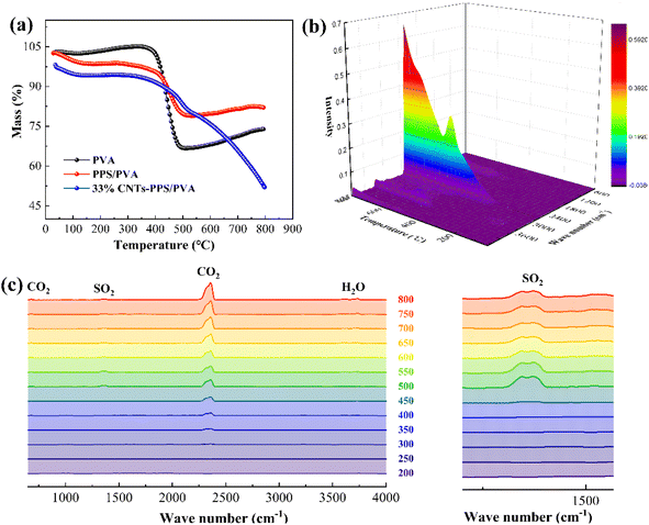 | ||
| Fig. 7 Thermal stability test, (a) TGA curves of PVA, PPS/PVA and 33% CNTs-PPS/PVA; (b and c) TG-IR spectra of 33% CNTs-PPS/PVA. | ||
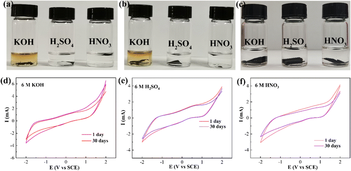
Cyclic voltammetry (CV) is an extremely sensitive test for surface changes, so the variation and properties of the CNTs-PPS/PVA composite under extreme conditions were investigated. As shown in Fig. 8a–c, after being soaked with a strong base (6 M KOH) and acids (6 M H2SO4 and HNO3) for 30 days, PVA and CNTs/PVA have changed, which may be caused by PVA depolymerization. For CNTs-PPS/PVA, these base and acid solutions still remain clear, which is due to that the CNTs-PPS/PVA film has terrific corrosion resistance and does not dissolve. Afterwards, CV was used to further evaluate whether the surface of CNTs-PPS/PVA has been changed, under the same conditions as above (Fig. 8d and e). All the CV tests were carried out in 0.2 M Na2SO4 with a scan rate 50 mV s−1 from −2 to 2 V. It can be observed that CNTs-PPS/PVA as a novel electrode has no obvious redox peaks with a potential range from −2 to 2 V, indicating that the acquired electrode only quickly conducts electrons rather than taking part in redox reactions. 30 days later, the CV curve overlaps the initial one in H2SO4, and there is a slight change in the curves of HNO3 and KOH. Besides, SEM follow-up reports the morphologies of the above soaked films, respectively. As shown in Fig. S5a–c,† the same dense and uniform distribution still remains, indicating that there is no visible change in the surface of the CNTs-PPS/PVA composite. Above conclusions manifest that the CNTs-PPS/PVA composite has outstanding corrosion resistance and is a highly conductive material, which will be widely used in new corrosion-resistant and conductive fields.
Conductivity and mechanical properties of the CNTs-PPS/PVA composite
The conductive performance of the as-prepared composite depends on the dispersion degree of CNTs in PPS, and the related electrical conductivities (σ) were measured using a digital four-probe tester. Table 2 exhibits the σ and mechanical properties of CNTs-PPS/PVA composites with CNTs increasing. When the doping content of CNTs is 33%, the σ reaches as high as 2941 S m−1 with an uneven rate of 0.02%, illustrating that CNTs-PPS/PVA possesses excellent electrical conductivity and CNTs distribute equally in the composite film.9,38 Moreover, the tensile strength of 25% CNTS-PPS/PVA can reach up to 452.1 MPa, which is 5.6 times that of PPS/PVA. Thus, this implies that a specific mixture of the CNTs-PPS/PVA composite has a significant influence on the mechanical performance of the composite.| Samples | σ (S m−1) | Non-uniform rate (%) | Tensile strength (MPa) |
|---|---|---|---|
| PPS/PVA | 111 | 1.0 | 80.8 |
| 5% CNTs-PPS/PVA | 286 | 0.0 | 115.8 |
| 10%CNTs-PPS/PVA | 370 | 1.0 | 218.6 |
| 20% CNTs-PPS/PVA | 2500 | 0.0 | 270.8 |
| 25% CNTs-PPS/PVA | 2631 | 1.0 | 452.1 |
| 33% CNTs-PPS/PVA | 2941 | 2.0 | 380.3 |
Applications
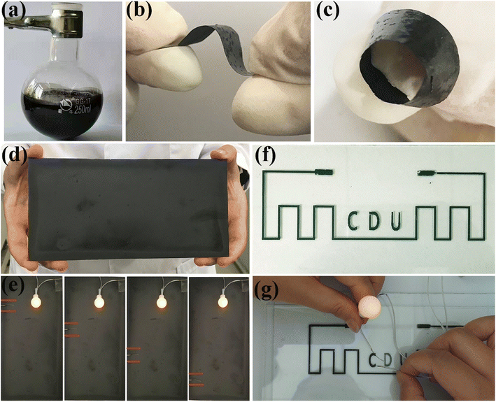
As a uniformly dispersed viscous suspension, CNTs-PPS/PVA has a variety of functional applications, as shown in Fig. 9. Given the stability of the mucus, CNTs-PPS/PVA can be prepared in amounts of about 150 mL or more (Fig. 9a) in the form of coating and films (Fig. 9a). When the doping ratio of CNTs is 25%, the composite suspension constructs a flexible film with a size of 2 × 5 cm2, which is a potential new flexible electrode with a wide potential window (Fig. 9b and c). Fig. 9d reveals that the CNTs-PPS/PVA composite can form highly conductive coating with a large size of 10 × 20 cm2. Furthermore, in the electrical conductivity application test at different positions, the brightness of a light emitting diode (LED) remains unchanged, indicating that CNTs fully link with each other and evenly distribute in the CNTs-PPS/PVA coating (Fig. 9e). Noteworthily, the dispersion system of CNTs-PPS/PVA as ink can be 3D printed on glass to yield printed circuits by fluid dispensing technology with a line width of 1 mm, and the excellent brightness of the LED can be obtained (Fig. 9f and g). The test results illustrate that the CNTs-PPS/PVA composite possesses outstanding electrical conductivity in both large and small sizes.Conclusion
In this work, a new mucus dispersion-annealing method was proposed for the fabrication and structural control of a CNTs-PPS/PVA composite. The morphology, size distribution, and quality loss observation simultaneously confirm that PVA mucus can prevent PPS particles from settling and promote the dispersion of CNTs and PPS both in theory and practice, improving the comprehensive performance of the CNTs-PPS/PVA composite. In this work, the as prepared CNTs-PPS/PVA composite possesses distinguished electrical conductivities of 2941 S m−1 with an uneven rate of 0.02%, reliable mechanical properties and excellent thermostability. Besides, it should be emphasized that the composite material in the form of coating and flexible films can all resist strong acids and alkalis for 30 days or more. The application potential of a CNTs-PPS/PVA suspension in printable circuits has also been proved. These conclusions illustrate that the CNTs-PPS/PVA composite is a novel multifunctional integrated material, and it will be highly promising in batteries, special functional materials and flexible electronics.Author contributions
Lingpu Jia: writing – original draft, software, methodology, investigation, conceptualization. Juan Hao: software, investigation, validation. Qingliang Fen: writing – review & editing, methodology, investigation. Huiming Li: data curation, supervision. Kunping Liu: writing – review & editing, funding acquisition.Conflicts of interest
There are no conflicts to declare.Acknowledgements
The work was supported by the Second Tibetan Plateau Scientific Expedition and Research Program (STEP) (No. 2019QZKK0201), the National Key Research and Development Program of Region innovation of Science and Technology Department of Sichuan Province (No. 2022YFQ0050) and the Introduction of Talent Research Start-up Fund of Chengdu University (No. 2081922036).References
- A. M. Díez-Pascual and A. L. Díez-Vicente, ACS Appl. Mater. Interfaces, 2014, 6, 10132–10145 CrossRef PubMed.
- H. Qi, L. Zhang, G. Zhang, T. Wang and Q. Wang, J. Colloid Interface Sci., 2018, 514, 615–624 CrossRef CAS PubMed.
- K. Stoeffler, S. Andjelic, N. Legros, J. Roberge and S. B. Schougaard, Compos. Sci. Technol., 2013, 84, 65 CrossRef CAS.
- D. Luo, M. Chen, J. Xu, X. Yin, J. Wu, S. Chen, L. Wang and H. Wang, Compos. Sci. Technol., 2018, 157, 119 CrossRef CAS.
- A. S. Rahate, K. R. Nemade and S. A. Waghuley, Rev. Chem. Eng., 2013, 29(6), 471 CAS.
- S. Pan, H. Shen and L. Zhang, Addit. Manuf., 2021, 47, 102247 CAS.
- Y. Zhou, L. Jia, T. Wang, Y. Du and C. Wang, Int. J. Hydrogen Energy, 2018, 43(15), 7356 CrossRef CAS.
- T. Wang, Y. Jiang, Y. Zhou, Y. Du and C. Wang, Appl. Surf. Sci., 2018, 44, 21 Search PubMed.
- P. Lin, S. Huang, Q. Liu, L. Zhao, H. Huang, C. Zhu, Y. Yu, Y. Li, Z. Zhu, K. Nie, L. Wang and H. Wang, Composites, Part B, 2021, 204, 108484 CrossRef CAS.
- J. Gu, Y. Guo, X. Yang, C. Liang, W. Geng, L. Tang, N. Li and Q. Zhang, Composites, Part A, 2017, 95, 267 CrossRef CAS.
- W. Ren, Y. Yang, J. Yang, H. Duan, G. Zhao and Y. Liu, Chem. Eng. J., 2021, 415, 129052 CrossRef CAS.
- L. Zhao, Q. Ge, J. Sun, J. Peng, X. Yin, L. Huang, J. Wang, H. Wang and L. Wang, Adv. Compos. Hybrid Mater., 2019, 2(3), 481 CrossRef CAS.
- S. Huang, P. Lin, H. Huang, L. Zhao, C. Zhu, Y. Yu, Z. Zhu, K. Nie, Q. Tang, L. Wang and H. Wang, Composites, Part B, 2020, 201, 108334 CrossRef CAS.
- Y. Shi, M. Liang, H. Wu, Y. Chen, S. Zhou, H. Zou, T. Sun and H. Zhang, Adv. Eng. Mater., 2021, 23(1), 2000787 CrossRef CAS.
- W. Luo, Q. Liu, Y. Li, S. Zhou, H. Zou and M. Liang, Composites, Part B, 2016, 9, 579 CrossRef.
- W. B. Russel, J. Rheol., 1980, 24(3), 287 CrossRef CAS.
- K. Toda and H. Furuse, J. Biosci. Bioeng., 2006, 102(6), 524 CrossRef CAS PubMed.
- J. Jeon and S. Koo, J. Magn. Magn. Mater., 2012, 324(4), 424 CrossRef CAS.
- W. D. Teng, M. J. Edirisinghe and J. R. Evans, J. Am. Ceram. Soc., 1997, 2, 486 Search PubMed.
- H. D. Koca, S. Doganay, A. Turgut, I. H. Tavman, R. Saidur and I. M. Mahbubul, Renewable Sustainable Energy Rev., 2018, 82, 1664 CrossRef CAS.
- S. M. S. Murshed and P. Estellé, Renewable Sustainable Energy Rev., 2017, 76, 1134 CrossRef CAS.
- J. Zanela, A. P. Bilck, M. Casagrande, M. V. E. Grossmann and F. Yamashita, Polímeros, 2018, 28(3), 256 CrossRef.
- A. Barman and D. M. Das, J. Inorg. Organomet. Polym., 2019, 30(6), 2248 CrossRef.
- C.-C. Li, M.-J. Li and Y.-P. Huang, J. Am. Ceram. Soc., 2017, 100(11), 5020 CrossRef CAS.
- X. Luo, L. Zhu, Y. C. Wang, J. Li, J. Nie and Z. L. Wang, Adv. Funct. Mater., 2021, 31(38), 2104928 CrossRef CAS.
- L. Zhao, J. Zhang, P. Cao, L. Kang, Q. Gong, J. Wang, Y. Zhang and Q. Li, Composites, Part B, 2021, 211, 108661 CrossRef CAS.
- R. Socher, B. Krause, M. T. Müller, R. Boldt and P. Pötschke, Polymer, 2012, 53(2), 495 CrossRef CAS.
- R. Yang, Z. Su, S. Wang, Y. Zhao and J. Shi, J. Thermoplast. Compos. Mater., 2017, 31(11), 1545 CrossRef.
- L. Jia, H. kou, Y. Jiang, S. Yu, J. Li and C. Wang, Electrochim. Acta, 2013, 107, 71 CrossRef CAS.
- I. Y. Prosanov and A. A. Matvienko, Phys. Solid State, 2010, 52(10), 2203 CrossRef CAS.
- J. Ben, Z. Song, X. Liu, W. Lü and X. Li, Nanoscale Res. Lett., 2020, 15(1), 1 CrossRef PubMed.
- P. Yan, W. Peng, F. Yang, Y. Cao, M. Xiang, T. Wu and Q. Fu, Polym. Degrad. Stab., 2022, 197, 109863 CrossRef CAS.
- Z.-Z. Fan, H.-W. He, X. Yan, R.-H. Zhao, Y.-Z. Long and X. Ning, Polymers, 2019, 11(3), 530 CrossRef PubMed.
- J. Xing, Q.-Q. Ni, B. Deng and Q. Liu, Compos. Sci. Technol., 2016, 134, 184 CrossRef CAS.
- E. M. Sadek, D. E. El-Nashar, A. A. Ward and S. M. Ahmed, J. Polym. Res., 2018, 25(12), 1 CAS.
- K. Coenen, F. Gallucci, B. Mezari, E. Hensen and M. van Sint Annaland, J. CO2 Util., 2018, 24, 228 CrossRef CAS.
- C. Sun, N. Zhao, Z. Zhuang, H. Wang, Y. Liu, X. Weng and Z. Wu, J. Hazard. Mater., 2014, 274, 376 CrossRef CAS PubMed.
- Y. L. An, C. Zhang, X. Yuan and Q. Y. Hou, Adv. Mater. Res., 2012, 454, 59 CAS.
Footnote |
| † Electronic supplementary information (ESI) available. See DOI: https://doi.org/10.1039/d2na00855f |
| This journal is © The Royal Society of Chemistry 2023 |

