 Open Access Article
In situ fabrication of cerium-incorporated hydroxyapatite/magnetite nanocomposite coatings with bone regeneration and osteosarcoma potential
B.
Priyadarshini
ac,
Arul Xavier
Stango
b,
M.
Balasubramanian
c and
U.
Vijayalakshmi
 *a
*a
aDepartment of Chemistry, School of Advanced Sciences, VIT, Vellore, 632 014, Tamil Nadu, India. E-mail: vijayalakshmi.u@vit.ac.in; lakesminat@yahoo.com; Fax: +91-416-224 3092; Tel: +91-416-2202464
bDepartment of Chemistry, Kalasalingam Academy of Research and Education, Krishnankoil, Srivilliputhur, Tamil Nadu 626126, India
cDept of Metallurgical and Materials Engineering Indian Institute of Technology-Madras (IIT Madras), Chennai, 600 036, India
First published on 10th August 2023
Abstract
With the ultimate goal of providing a novel platform able to inhibit bacterial adhesion, biofilm formation, and anticancer properties, cerium-doped hydroxyapatite films enhanced with magnetite were developed via spin-coating. The unique aspect of the current study is the potential for creating cerium-doped hydroxyapatite/Fe3O4 coatings on a titanium support to enhance the functionality of bone implants. To assure an increase in the bioactivity of the titanium surface, alkali pretreatment was done before deposition of the apatite layer. Scanning electron microscopy (SEM) in conjunction with energy-dispersive X-ray (EDX) spectroscopy, X-ray diffraction (XRD) analysis, and Fourier transform-infrared (FTIR) spectroscopy were used to evaluate coatings. Coatings demonstrated good efficacy against Staphylococcus aureus and Escherichia coli, with the latter showing the highest efficacy. In vitro bioactivity in simulated body fluid solution showed this material to be proficient for bone-like apatite formation on the implant surface. Electrochemical impedance spectroscopy was undertaken on intact coatings to examine the barrier properties of composites. We found that spin-coating at 4000 rpm could greatly increase the total resistance. After seeding with osteoblastic populations, Ce-HAP/Fe3O4 materials the adhesion and proliferation of cells. The heating capacity of the Ce-HAP/Fe3O4 film was optimal at 45 °C at 15 s at a frequency of 318 kHz. Osseointegration depends on many more parameters than hydroxyapatite production, so these coatings have significant potential for use in bone healing and bone-cancer therapy.
1. Introduction
Ti–6Al–4V metallic implants have significant roles in orthopedic and dental applications for fixation/replacement of damaged bones.1 They have excellent anti-corrosion properties, toughness, as well as high ductility with strength. A Ti–6Al–4V metallic implant forms a native oxide layer in nanometer ranges on its surface if exposed to air. This surface protects metals from corrosion and makes them stable in physiological body fluids. Surface modification of Ti alloys can enhance the properties of implants for cell attachment, biocompatibility, bioactivity, and also increases the bone-to-tissue/implant adhesion strength in a biological system.2–4 The surface property of metals can be improved by chemical approaches such as alkali/acid etching, sol–gel method, anodic oxidation, chemical-vapor deposition, or treatment with hydrogen peroxide. Surface contamination of metals can be removed effectively by acid pre-treatment using H2SO4, HCl, or Na2S2O8 as decontaminating agents.5 Acid treatment followed by alkali treatment improves the solubility of alloys by apatite formation and increases the bond strength between the implant-to-bone interface.The following factors must be known to fully control deposition: (i) molecular stability in deposition settings; (ii) stability of the surface in deposition conditions; (iii) type of interaction between a molecule and the surface. Controlling the dynamic behavior of the magnetic characteristics of a molecule is essential for utilizing molecular nanomagnets on surfaces. To select the ideal deposition approach for a given molecule/surface system, detailed understanding of the chemical and physical properties of all system components is required.6,7 Sol–gel coatings have drawn a lot of attention due to the utilization of simple and less expensive processes for the synthesis and deposition of HAP coatings on various metallic implants. Low process temperatures, the ability to coat substrates with complex geometries, homogenous microstructure, and fine control of chemical composition are advantages.8,9 Sol–gel methods are predominantly used to deposit a thin layer on the metal surface by spin coatings or dip coating. This practice precisely controls the film thickness to provide uniformity, and improves bioactivity by enhancing interactions between bone tissue and the implant.10–13
HAP is a commonly used bioactive ceramic material for coatings due to its non-toxicity, biocompatibility, bioactivity, osteointegration, and osteoblast proliferation. It has been used as a restorative material to promote bone growth in non-loadbearing applications and cementless hip surgery.14–16 Despite the many advantages of HAP, it has poor anti-bacterial properties, which can lead to implant removal due to infection. To overcome this problem, doping HAP with monovalent, divalent, trivalent, or tetravalent elements can improve the antibacterial resistance as well as physical properties of HAP without altering its structure.17–20
Cerium is an abundant element in earth. It exists in two oxidation states (3+/4+) and plays a vital part in various fields. It has been widely used as a catalyst, in dental/bone fillings, to aid bone healing, to treat Alzheimer's disease and neurogenerative diseases, and as a protective barrier against radiation. It has excellent antibacterial-restriction behavior due to the presence of reactive oxygen species (ROS) that damage the cell wall of bacteria and leads to their death. It also acts as an antioxidant and scavenger of free radicals. Doping of cerium into a HAP lattice can improve the properties of HAP, and one of the major advantages of cerium is its excellent anticorrosion property.21,22 Sol–gel coating with cerium protects metals from corrosion by a self-healing property. Mathi et al. (2017) fabricated a cerium-substituted HAP/PVA coating on Ti–6Al–4V. They reported that the developed coating showed improved corrosion resistance and could be used in orthopedic applications.23 Ciobanu et al. (2015) developed cerium-doped HAP/collagen coatings on Ti alloys. They demonstrated that these coatings had great potential for orthopedic implants with excellent antibacterial and osteointegration properties.24
Magnetic nanoparticles (NPs) are emerging materials in biomedical engineering. They have been intensively developed for magnetic resonance imaging (MRI), as drug delivers/carriers, as well as in tissue restoration, bone healing, biosensing, and hyperthermia treatment.25–31 By osteo-mimetic processes, magnetic NPs can influence functional bone tissues. Magnetic materials and their composites are frequently used for wound healing and pain relief. Incorporation of magnetic NPs into biomaterials can improve bioactivity, biological effects, and cellular functions. Fe3O4 NPs are considered potential candidates for tissue engineering because they have excellent biocompatibility and anticorrosion property, are non-toxic and specific loss power (SPL) biocatalysts, and their physical properties are environmentally friendly. In particular, a Fe3O4 composite with HAP enhances bone healing through the stimulation of osteoconductivity.32–35 Wu et al. (2010) developed Ca–P–Fe3O4 composite materials and undertook in vitro and in vivo studies. Their in vitro studies showed enhanced attachment, proliferation, and differentiation of osteoblasts. Their in vivo studies revealed the growth and formation of bone.36 Anjaneyulu and Vijayalakshmi (2017) prepared HAP/Fe3O4 composite coatings on Ti–6Al–4V using a sol–gel method, and concluded that the obtained coatings acted as a semi-protective barrier against corrosion.37 Singh et al. (2019) revealed the corrosion behavior of HAP/Fe3O4/CS composite coatings on Mg alloys, and predicted that the composite coatings could serve as a promising material with enhanced surface properties and corrosion resistance.38 On the contrary, in the presence of an external magnetic field, magnetite materials develop heat due to Néel relaxation, Brownian relaxation, and hysteresis loops. Magnetite materials have high magnetic movement at 42–45 °C in the presence of an external magnetic field and can kill cancerous cells due to hemorrhage, stasis, and vascular occlusion, whereas normal cells survive without any damage. This is a significant method to kill cancer cells in safe way, and US Food and Drug Administration-approved magnetite materials are biocompatible materials in the human body.39,40
Fabrication of Fe3O4 composite coatings with cerium-doped HAP by a sol–gel method on Ti–6Al–4V has rarely been reported. In the present study, Ce-doped HAP/Fe3O4 composite coatings were developed on Ti–6Al–4V via spin coating at various centrifugal forces. We report, for the first time, that cerium-doped hydroxyapatite (HAP)/Fe3O4 coatings produced via spin coating have physicochemical, antibacterial, and anticancer properties. Several biophysical features of these coatings were measured. We also attempted to investigate the magnetic heating capacity of Ce-HAP/Fe3O4 through hyperthermia treatment.
2 Experimental procedures
2.1 Materials and methods
Surgical grade-2 Ti–6Al–4V alloy, ceric(IV) ammonium nitrate [(NH4)2·Ce(NO3)6-SDFCL, 98.5%], calcium nitrate tetrahydrate [Ca(NO3)2·4H2O-SDFCL, 99%], triethyl phosphite [P(OC2H5)3, 98%], iron sulfate (FeSO4), anhydrous iron chloride (FeCl3), aqueous ammonia (aq. NH3), double-distilled water, phosphate-buffered saline (PBS), and dimethyl sulfoxide were purchased.2.2 Surface treatment of Ti–6Al–4V
A surgical grade-2 Ti–6Al–4V sheet was made into 10 mm × 10 mm × 3 mm sections and polished with silicon carbide grit paper (200–1200 grade). This was followed by diamond polishing to create a mirror surface. All metals were degreased ultrasonically with acetone for 30 min and then washed with double-distilled water. Substrates were treated with H2SO4![[thin space (1/6-em)]](https://www.rsc.org/images/entities/char_2009.gif) :
:![[thin space (1/6-em)]](https://www.rsc.org/images/entities/char_2009.gif) HCl
HCl![[thin space (1/6-em)]](https://www.rsc.org/images/entities/char_2009.gif) :
:![[thin space (1/6-em)]](https://www.rsc.org/images/entities/char_2009.gif) H2O in a 1
H2O in a 1![[thin space (1/6-em)]](https://www.rsc.org/images/entities/char_2009.gif) :
:![[thin space (1/6-em)]](https://www.rsc.org/images/entities/char_2009.gif) 1
1![[thin space (1/6-em)]](https://www.rsc.org/images/entities/char_2009.gif) :
:![[thin space (1/6-em)]](https://www.rsc.org/images/entities/char_2009.gif) 1 ratio at 60 °C for 1 h and then with 4 M NaOH for 24 h at 60 °C. The acid and alkali-treated metal substrates were dried in an oven at 80 °C prior coating with the sol–gel method.
1 ratio at 60 °C for 1 h and then with 4 M NaOH for 24 h at 60 °C. The acid and alkali-treated metal substrates were dried in an oven at 80 °C prior coating with the sol–gel method.
2.3 Synthesis of Fe3O4 NPs
In this co-precipitation method, FeSO4![[thin space (1/6-em)]](https://www.rsc.org/images/entities/char_2009.gif) :
:![[thin space (1/6-em)]](https://www.rsc.org/images/entities/char_2009.gif) FeCl (2
FeCl (2![[thin space (1/6-em)]](https://www.rsc.org/images/entities/char_2009.gif) :
:![[thin space (1/6-em)]](https://www.rsc.org/images/entities/char_2009.gif) 1 ratio) was dissolved in double-distilled water and the solution stirred for 2 h. The pH was maintained at 10 by adding aqueous ammonia to the solution and stirring for 1 h at 80 °C. The obtained black precipitate was collected from the suspension by applying an external magnetic field. The retrieved magnetite material was dried in an oven for 1 h at 100 °C. In accordance with our previous publication,26 Fe3O4 particles were ∼62 nm in size.
1 ratio) was dissolved in double-distilled water and the solution stirred for 2 h. The pH was maintained at 10 by adding aqueous ammonia to the solution and stirring for 1 h at 80 °C. The obtained black precipitate was collected from the suspension by applying an external magnetic field. The retrieved magnetite material was dried in an oven for 1 h at 100 °C. In accordance with our previous publication,26 Fe3O4 particles were ∼62 nm in size.
2.4 Synthesis of Ce-HAP/Fe3O4 sol
Based on in vitro biological assessments and analytical methodologies, we found that 1.25% Ce@HAP–5% Fe3O4 composites NPs demonstrated remarkable outcomes in our previous research.26 Accordingly, in this investigation, we chose 1.25% Ce@HAP–5% Fe3O4 composites using sol–gel spin-coating.26 First, 1.25% of Ce-doped HAP was prepared by dissolving calcium nitrate tetrahydrate (0.98 M) and ceric ammonium nitrate (0.0125 M) in ethanol for 2 h. Separately, a phosphate precursor (0.6 M) was dissolved in ethanol and stirred for 2 h. The phosphate precursor was added dropwise to the Ca/Ce solution with constant stirring for 2 h to enhance the hydrolysis of calcium/phosphorus sources. The suspension was allowed to stand for 24 h, refluxed for 16 h, followed by solution evaporation in a water bath to create a sol by polycondensation of Ca–O–P bonds.2.5 Ce-HAP/Fe3O4 fabrication and spin coating
To the 1.25% Ce-HAP sol was added 5% Fe3O4 nanocomposite followed by mixing to obtain a composite mixture. This blend underwent ultra-sonication for 30 min. The obtained mixture was used as a sol for spin coating. Then, 2 ml of the Ce-HAP/Fe3O4 sol was coated on alkali-treated Ti–6Al–4V at various spin rates (2000, 3000, or 4000 rpm) for 20 s at three accelerations.37,41 The coated substrates were dried in an oven for 30 min at 80 °C immediately after spinning. This process were repeated for thrice to achieve a triple-layer coating of uniform thickness.For consistent deposition of a homogeneous thin film, spin-coating processes are user-friendly, adaptable, affordable, and extremely effective. Thus, this method has been widely applied to the fabrication of solution-processed organic/inorganic material. These operations are carried out regularly to construct thick layers.42–44 Also, the viscosity of the solution and surface tension of the droplet must also be considered.45–47 These characteristics closely resemble the properties of a pure common organic solvent and diluted solutions of magnetic compounds.6 The morphology and solid-state order of the deposited layer are closely related to the spin-coating performances of Ce-HAP/Fe3O4. These properties are greatly influenced by the processing conditions used during spin-coating, such as the properties of the solvent, substrate temperature, surface characteristics, ambient solvent vapor pressure, and spinning speed/duration.48,49 Despite the intrinsic constraints of the coating material, meticulous oversight of all processing parameters can maximize the performance of Ce-HAP/Fe3O4, produced by spin-coating. For uniform coverage, speeds between 500 rpm and 5000 rpm are frequently used. Fume exhausts and drying periods must also be considered to control for high volumes.50 Therefore, in this investigation, different spinning rates (rpm) with three repetitions lasting 20 s were used to achieve a consistent coating thickness.
2.6 Surface characterization
The vibrational modes in infrared (IR) region of coatings were assessed by a Fourier transform-IR spectrophotometer (IR Affinity I; Shimadzu) in the spectral range 4000 to 400 cm−1 using KBr disks (0.01%). The phase conformation and purity were determined by X-ray diffraction (XRD) analysis with a step size of 0.02 and scanning rate of 1.2° min−1. Surface topography, coating thickness, and elemental composition were examined by scanning electron microscopy/energy-dispersive spectroscopy (SEM-EDS). The wettability of coatings was analyzed by contact-angle measurement using sessile drop methods. That is, water (6 μl) was dropped on the coating using a micro-syringe and wettability was measured by a goniometer fenced with a camera. The surface roughness of all uncoated (Ti–6Al–4V and AT–Ti–6Al–4V) and composite-coated substrates was measured by a surface profilometer.2.7 In vitro bioactivity test
An in vitro bioactivity study was undertaken in simulated body fluid (SBF) solution by immersing Ce-HAP/Fe3O4 coatings in 60 ml of SBF solution. This method was based on ISO standard 23![[thin space (1/6-em)]](https://www.rsc.org/images/entities/char_2009.gif) 317 (“in vitro estimation for implant surgery for apatite growth in simulated body fluid”). The solution was prepared by dissolving NaCl (7.996 g), NaHCO3 (0.350 g), KCl (0.224 g), K2HPO4 (0.228), MgCl2·6H2O (0.305 g), CaCl2 (0.278 g), Na2SO4 (0.071 g) and C(CH2OH)3 NH2·HCl (6.057 g) in double-distilled water at pH 7.4 whereby the ionic concentration of the solution is equal to that of blood plasma in humans. Bioactivity was monitored for 10 and 20 days by regular replacement of SBF to maintain the ionic concentration. After the pre-determined immersion period, all samples were rinsed with double-distilled water and dried at 80 °C.
317 (“in vitro estimation for implant surgery for apatite growth in simulated body fluid”). The solution was prepared by dissolving NaCl (7.996 g), NaHCO3 (0.350 g), KCl (0.224 g), K2HPO4 (0.228), MgCl2·6H2O (0.305 g), CaCl2 (0.278 g), Na2SO4 (0.071 g) and C(CH2OH)3 NH2·HCl (6.057 g) in double-distilled water at pH 7.4 whereby the ionic concentration of the solution is equal to that of blood plasma in humans. Bioactivity was monitored for 10 and 20 days by regular replacement of SBF to maintain the ionic concentration. After the pre-determined immersion period, all samples were rinsed with double-distilled water and dried at 80 °C.
2.8 Inductively coupled plasma-optical emission spectroscopy (ICP-OES)
The ionic concentration of the Ca2+, PO43, Ce, Fe, and O present in coatings was determined by ICP-OES. Dissolution of the ionic concentration in SBF solution for apatite formation was identified by this method. The experiment was carried out by immersing coatings in SBF solution for 5, 10, or 20 days. Then, 20 ml of each immersed solution was placed in a Falcon™ tube and stored in refrigerator prior to analyses.2.9 Vickers micro-indentation test
A Vickers microhardness tester was used to assess the microhardness of the coating deposited on Ti–6Al–4V. A load of 0.1 kgf to 1.0 kgf was applied to the coating surface with a dwell time of 15 s to fortify the indentation on the coating substrates. The Vickers hardness (Hv) was calculated using the following equation:| Hv = 1.844P/d2 (kg mm−2) | (1) |
2.10 Bonding strength
The binding force of the implant and coating was evaluated by the pull-off test using a universal testing machine (Instron). Standard methods were adopted to define the degree of shear strength between the metal substrate and calcium phosphate-based composite coating. The test was carried out on both sides. One side of the specimen was attached to epoxy glue. The other side of the specimen was attached to the coating. Delamination was observed by applying a shear strength of 500 psi with the crosshead of 5 mm min−1 at 175 °C.2.11 In vitro corrosion studies
The corrosion-resistance behavior of bare metal, AT–Ti–6Al–4V, and Ce-HAP/Fe3O4 deposited on AT–Ti–6Al–4V was studied by electrochemical impedance spectroscopy (EIS). The experiment was undertaken in SBF solution using a three-electrode setup: counter electrode (saturated calomel), reference electrode, and working electrode (substrate). EIS was undertaken at a logarithmic frequency range from 100![[thin space (1/6-em)]](https://www.rsc.org/images/entities/char_2009.gif) 000 Hz to 0.01 Hz. A potentiodynamic polarization study was analyzed by scanning at −0.300 V to +0.300 V at a scan rate of 1 mV min−1
000 Hz to 0.01 Hz. A potentiodynamic polarization study was analyzed by scanning at −0.300 V to +0.300 V at a scan rate of 1 mV min−1
2.12 Colony formation
The resistance of thin-film coatings to microorganisms was evaluated by counting the number of colony-forming units (CFUs) against Gram-negative (Escherichia coli, Pseudomonas aeruginosa) and Gram-positive bacteria. Entire uncoated and coated substrates were autoclaved at 120 °C for 30 min. A test microorganism at 109 CFU per ml was cultured in lysogeny broth (LB) medium in 24-well plates. Subsequently samples were added to each plate containing microbes followed by incubation for 24 h at 37 °C. Thereafter, 5 ml of bacterial culture from 24-well plates were spread on Petri plates containing agar solution and incubated for 24 h at 37 °C. The number of CFUs on plates was calculated using the following equation:| CFU per ml = number of colonies × dilution factor/volume of culture | (2) |
2.13 Bacterial morphology
The above-mentioned Gram-positive and Gram-negative bacteria were cultured in LB medium at 109 CFU per ml. Then, 2 ml of the culture was transferred to the LB medium present in 24-well plates. All test samples were immersed in 24-well plates and incubated for 12 h or 24 h. After pre-set incubation periods, test samples were detached and washed with PBS followed by fixation with 2% paraformaldehyde and glutaraldehyde. Each sample was fixed with 70% ethanol and freeze-dried under a vacuum. The resultant morphology and cell death were observed under a scanning electron microscope.2.14 Cytotoxicity studies
The cytotoxicity of uncoated and coated substrates was studied using human osteoblast-like cells (MG-63) via the MTT assay (an assay used to estimate cell viability and metabolic activity through colorimetric enzymatic reduction of tetrazolium dye). Dulbecco's modified Eagle's medium and minimal essential medium were used to stimulate cell growth. Test samples were sterilized before cell culture to avoid contamination. First, MG-63 cells were cultured in serum-free medium at 37 °C in an atmosphere of 5% CO2. Cultured cells were transferred to 24-well plates (100 μl cell per well) containing test samples and incubated at 24, 48, or 72 h at 37 °C in an atmosphere of 5% CO2. After cultivation, the medium was replaced with MTT solution (0.45 mg ml−1) followed by incubation at 37 °C for 4 h. Consequently, the MTT solution was washed with dimethyl sulfoxide (100 μl) to remove formazan crystals, and absorbance was measured at 540 nm.2.15 Morphology and adhesion of cells
MG-63 cells were cultured on coatings in 24-well plates containing medium and incubated for 24 h, 48 h, or 72 h in an atmosphere of 5% CO2 at 37 °C. After incubation, substrates were removed and washed with PBS to remove unadhered cells. Following cell fixation using 2% paraformaldehyde and glutaraldehyde, sodium cacodylate buffer (0.1 M) was added to substrates and incubated overnight at 4 °C. The overnight cultured samples were washed with 70% ethanol and freeze-dried. The morphology, growth, and adhesion of cells were observed under a scanning electron microscope.2.16 Assays to identify living and dead cells
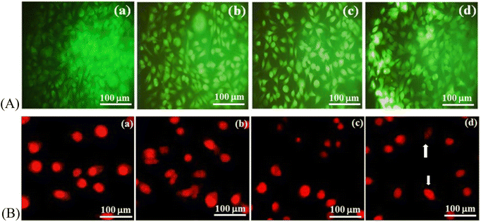
An assay to identify living and dead cells was undertaken by culturing MG-63 cells on coatings for 24 h, 48 h, or 72 h in a humidified atmosphere with 5% CO2 at 37 °C. The culture medium was replaced with AO/EB (10 mg ml−1). Cells were stained with propidium iodide and incubated for 10 min. Henceforth, substrates were removed and washed with PBS in the dark. Each sample was observed under a fluorescence microscope.2.17 Hyperthermia treatment
The heating capacity of Ce-HAP/Fe3O4 was assessed using an induction heating system (Easyheat 8310; Ambrell) in the presence of an external magnetic field. A frequency of 318 kHz and field strength of 22.6 kA m−1 were used. The coated metal sample was immersed in 2 ml of water in a 10 ml Falcon tube and placed in a copper coil. The instrumentation consisted of a copper induction loop (4.5 cm × 6.3 cm) and thermocouple. The temperature of the sample was measured.2.18 In vitro magnetic hyperthermia treatment
The coating with maximum heating efficiency was investigated for hyperthermia therapy using an osteosarcoma (SAOS-2) cell lines. The latter were cultured as described above. After trypsinization, cells were suspended at 106 cells per ml in a 20 ml Falcon tube. Cells cultured without a sample were controls. A coating seeded with cells was incubated for 12 h to measure cellular uptake of NPs. All experimental cultures were placed in a hyperthermia coil at a frequency of 319 kHz, AC voltage of 151.2 Å for 1 h, in a field strength of 22.6 kA m−1. The temperature was recorded with a temperature probe attached to the instrument. After heat treatments, the sample with cells was incubated for 24 h, 48 h, or 72 h. Percent cell viability was measured using the following equation:| % cell viability = treated cellsabsorbance of 570 nm/control cellsabsorbance of 570 nm × 100 | (3) |
Cells were stained with propidium iodide to observe apoptotic and non-apoptotic cells under a fluorescence microscope.
2.19 Statistical analyses
Experiments were repeated thrice. Data are the mean ± standard deviation. The level of significance was determined by one-way ANOVA. P < 0.05 was considered significant.3 Results and discussion
3.1 FT-IR spectroscopy
The FT-IR spectrum of Ce-HAP/Fe3O4 coatings is displayed in Fig. 1. The bands obtained from the spectrum revealed no change in the functional groups present in Ce-HAP/Fe3O4 coatings. Deposition of Ce-HAP/Fe3O4 did not affect the phase formation of HAP or Fe3O4 composite. The characteristic peaks present at 1098, 1028, 550, and 603 cm−1 demonstrated the existence of PO43− groups in HAP. Peaks at 1098 and 1028 cm−1 were attributed to the asymmetrical stretching mode of the P–O bond. Bands at 550 and 603 cm−1 were assigned to the bending mode of the O–P–O bond. Peaks at 3373 and 631 cm−1 were assigned to the stretching and bending modes of the O–H group. The band at 563 cm−1 corresponded to the Fe–O group present in the Fe3O4 composite.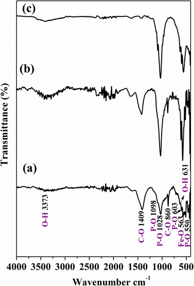 | ||
| Fig. 1 ATR-FTIR analysis of Ce-HAP/Fe3O4 composite coating on Ti–6Al–4V at 2000 rpm (a), 3000 rpm (b), 4000 rpm (c). | ||
Bands observed at 1409 and 860 cm−1 were attributed to C–O bonds; the presence of these bands showed that CO32− groups were substituted for PO43− groups in the structure forming a B-type carbonate apatite. The carbonate peak was due to the presence of CO2 in the atmosphere and was formed during spin-coating of the composite. However, C–O bonds were absent in the Ce-HAP/Fe3O4 sample coated at 4000 rpm (Fig. 1c). Therefore, FT-IR spectra showed the existence of functional groups of the Ce-HAP/Fe3O4 composite deposited on Ti–6Al–4V. The higher intensities of PO43− bonds denoted that the Fe–O functional group merged together in the region 637–550 cm−1. Further interaction of the Ce-HAP/Fe3O4 composite on the Ti–6Al–4V surface was confirmed by XRD patterns.
3.2 XRD patterns
The crystallinity, phase formation, and purity of the Ce-HAP/Fe3O4 composite were confirmed by XRD analysis (Fig. 2). The peaks observed at 2θ 36.07 correspond to the hkl values of (100). The other hkl values, such as (002) (101) (102) (110) (211) (112), corresponded to the crystalline nature of the Ti–6Al–4V alloy. The major characteristic peaks of HAP appeared at 2θ = 32.1 respective to the (211) plane. For Fe3O4, the peak at 2θ = 35.7 at the (311) plane was resolved. Diffraction peaks at 29.0, 34.1, 40.7, 47.7, 49.2, 50.6, and 53.1 were in good agreement with the standard HAP pattern with JCPDS file 09-0432.25,41 Peaks related to cerium did not appear, which confirmed formation of pure HAP without a secondary phase. The coating produced at lower rpm values of 2000 and 3000 showed lower peak intensity of the Ce-HAP/Fe3O4 composite. Compared with 3000 rpm, Ce-HAP/Fe3O4@2000 rpm showed an increased peak intensity of Ti alloys whereas, at a higher rpm of 4000, the coating exhibited a higher peak intensity of HAP and Fe3O4 composite.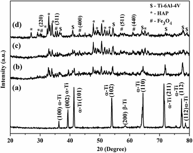 | ||
| Fig. 2 XRD analysis of, Ti–6Al–4V (a) Ce-HAP/Fe3O4 composite coating on Ti–6Al–4V acquired at 2000 rpm (b), 3000 rpm (c), 4000 rpm (d). | ||
By controlling the centrifugal force, one can obtain coatings without changing the stoichiometry or nature of composite coatings. XRD patterns confirmed the presence of all patterns corresponding to the Ce-HAP/Fe3O4 nanocomposite and Ti–6Al–4V. There was some marginal loss of crystallinity in coatings due to the existence of magnetite material. This result suggested that the Ce-HAP/Fe3O4 composite had been deposited on Ti–6Al–4V.
3.3 Surface roughness
The surface texture of bare metal and coatings was quantified by a surface profilometer and the measurement is given in Table 1. The sample exhibited surface roughness of 1.56 ± 0.6 μm for Ti–6Al–4V after polishing with grit paper, whereas subsequent chemical treatment of the metal showed increased surface roughness for alkali-treated metals with the value of 5.58 ± 0.54 μm. Ce-HAP/Fe3O4 composite coatings exhibited increased roughness to a final value of 7.1 ± 0.1 μm. Deligianni et al. postulated that increased roughness enhances the attachment and proliferation of cells through the grooves underneath the rough surface, which improves the adhesion strength of the bone implant.51| Sample code | R a (μm) surface roughness |
|---|---|
| Bare Ti–6Al–4V | 1.56 ± 0.9 |
| AT–Ti–66Al–4V (alkali treated) | 5.58 ± 0.54 |
| 2000 rpm | 5.04 ± 0.01 |
| 3000 rpm | 4.8 ± 0.4 |
| 4000 rpm | 7.1 ± 0.1 |
3.4 Scanning electron microscopy (SEM)
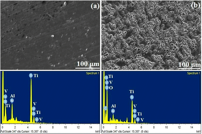
SEM provided direct information of bare and alkali-treated metal surfaces, and the typical topography is shown in Fig. 3. Significant differences were observed in polished and alkali-treated samples. Bare metal exhibited a smooth-to-furrow-like structure. The alkali-treated substrate had a porous structure on the Ti–6Al–4V surface. The surface morphology of the Ce-HAP/Fe3O4 composite coating prepared by various centrifugal forces is depicted in Fig. 4. A magnified image of coatings produced at 4000 rpm is shown in Fig. 4d. The surface structure of the coating had a needle-like morphology. Coatings obtained at 2000 rpm had a non-uniform, protuberance-like structure on the surface. In this case, the sol was not spread uniformly on the surface and it formed aggregates during solvent evaporation. Moreover, the coating retrieved at 3000 rpm appeared non-uniform with a prickle-like structure along with a flat surface. According to Fig. 4d, substrates were uniformly spread on the surface and had a fine structure. A needle-like-to-flake-like surface appeared for the coating derived at 4000 rpm when compared with other surfaces, and lacked uniformity. The random arrangement of the needle-like morphology was influenced by Fe3O4 nanocomposites.37 Fe3O4 nanocomposites formed aggregates and spread on the surface by integrating HAP crystals or by crossing the crystal surface.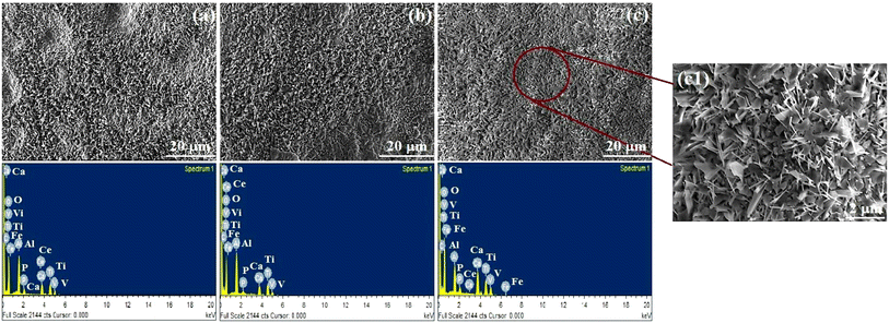 | ||
| Fig. 4 SEM Micrograph and EDS analysis of Ce-HAP/Fe3O4 composite spin coated at 2000 rpm (a), 3000 rpm (b), 4000 rpm (c). | ||
Coatings appeared to be non-homogeneous at 2000 rpm and 3000 rpm due to the initial stability of the sol over implants through spinning, which resulted in discontinuous deposition of the thin film. Spin-coating methods used for the deposition of Ce-HAP/Fe3O4 on alkali-treated Ti–6Al–4V are greatly influenced by the centrifugal force and number of deposition cycles to control the thickness. Using this method, the previously reported flat surface of the Ce-HAP coating52 was modified by the addition of Fe3O4 in Ce-HAP. This action resulted in interconnected needle-to-flake-like peaks expected to improve bone bonding and biocompatibility. The EDS spectrum of Ce-HAP/Fe3O4 coatings confirmed the presence of Ca, P, O, Ce, and Fe. Elemental analyses revealed that Fe3O4 along with cerium prevailed in coatings.
3.5 In vitro bioactivity (“biomineralization”)
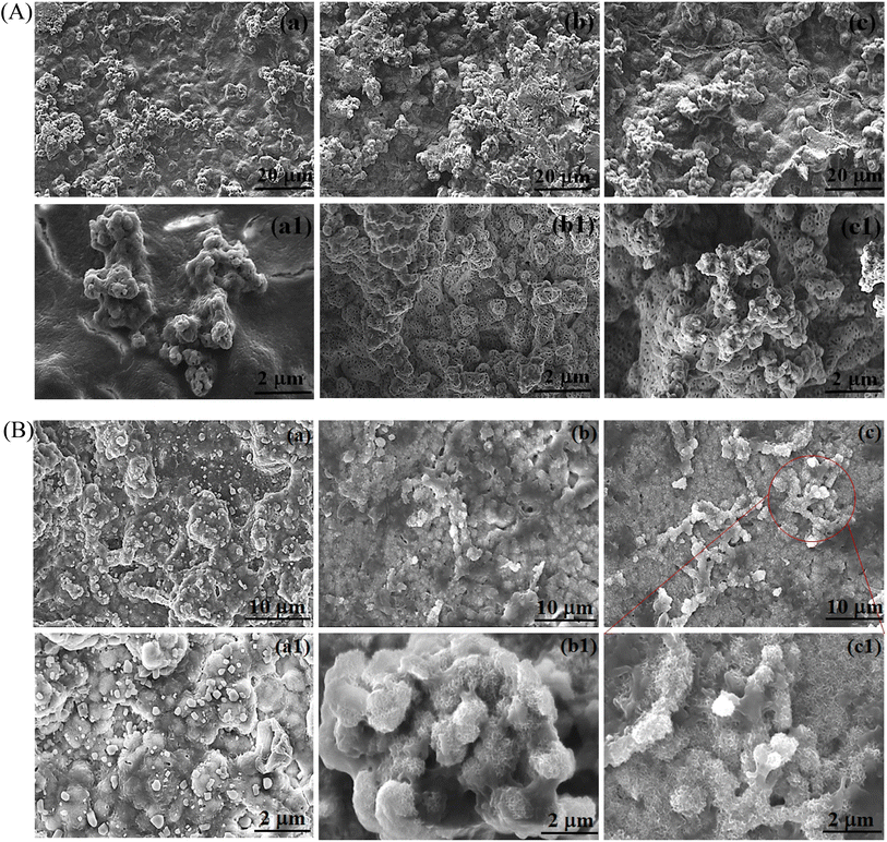
The typical features of biomineralization and surface morphology of Ce-HAP/Fe3O4 deposition on AT–Ti–6Al–4V were revealed after immersion in SBF solution for 10 or 20 days (Fig. 5A and B). Biomineralization enables interaction with host tissue. Apatite formation on the substrate depends on the temperature, pH, chemical composition, and dissolution rate. Additional immersion time in SBF solution enhanced the apatite-forming ability of the coating in vitro. This behavior improve osteoconduction, which could promote formation of new bone in vivo.Coatings after 10 days of immersion showed nucleation with the formation of smaller granular aggregates on the surface with a dense layer (Fig. 5A). In comparison, the coating obtained at 3000 and 4000 rpm showed a ball-like apatite with spherical micropores on the coated surface. A significant difference was not perceived for coatings soaked in SBF for 10 days. All samples subjected to SBF immersion showed a granular structure. After 20 days of immersion, mineral deposition on the surface was observed with a fiber-like apatite that propagated the entire surface of the coatings (Fig. 5B). As the duration of immersion increased, apatite formation also increased and the granules were denser. This observation suggested the nucleation of calcium phosphate as a micro-spherule network on the coating surface. The release of ions from the Ce-HAP/Fe3O4 coating surface in SBF solution is thought to be the cause of the bioactivity of these coatings. It has been demonstrated that these ions—which also include cerium, calcium, and iron—stimulate particular biological reactions. For instance, the antioxidant capabilities of cerium ions can reduce oxidative stress and increase cell viability. Iron ions can regulate biological activities, whereas calcium ions are essential for bone formation. The coating surface can also facilitate formation of a layer of calcium phosphate, thereby mimicking the natural composition of bone and promoting osseointegration.53,54
Apatite formation on the coating surface was due to the presence of Fe3O4. Fe3O4 hydrolyzed to form Fe–OH, which encouraged the heterogeneous nucleation of calcium phosphate in SBF. Therefore, these features revealed that Ce-HAP/Fe3O4 composite coatings on AT–Ti–6Al–4V induced apatite formation through nucleation and dissolution. This bone-like apatite increases the bone-bonding ability between surfaces to the coating interface in a living system. EDS spectra (Fig. 6) confirmed the presence of Ce, Fe, Ca, P, O, Ti, Al, and V.
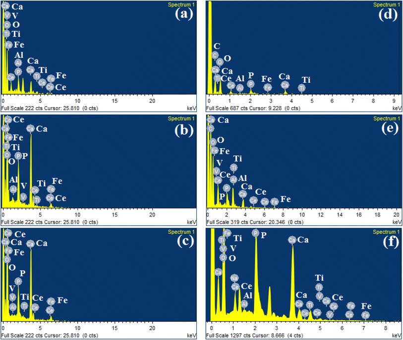 | ||
| Fig. 6 EDS spectrum of SBF immersed Ce-HAP/Fe3O4 composite coating on Ti–6Al–4V 2000 RPM (a), 3000 RPM (b), 4000 RPM (c) for 10days and (d–f) for 20 days. | ||
Elemental release from the Ce-HAP/Fe3O4 coating into a physiologically mimicked solution (SBF) was studied by ICP-OES for 0, 10, and 20 days (Fig. 7). Release of calcium and phosphorus ions increased in the initial immersion period, and the same behavior was noted for cerium and iron ions. Moreover, there was a decrease in the elemental concentration in SBF at 20 days, which revealed formation of a CaP layer during interaction with the physiological solution. Hence, the ions released from the coatings participated in bioactivity and antibacterial activity, and could improve the biological property.
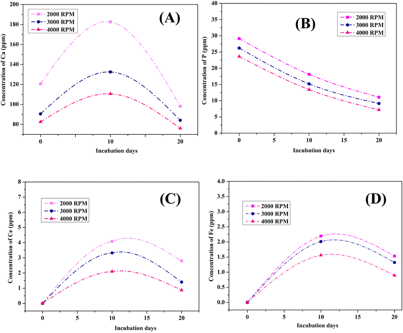 | ||
| Fig. 7 Ionic concentration of Ca (A); P (B); Ce (C) and Fe (D) in Ce- HAP/Fe3O4 nanocomposite Coatings in SBF for 0, 10 and 20 Days. | ||
3.6 Cross-section view of coatings
The thickness of triple-layer coatings was analyzed through a cross-section view via SEM (Fig. 8). The coatings displayed a thickness of 120, 78, and 80 μm at 2000, 3000, and 4000 rpm, respectively. Two distinct regions could be distinguished as a coating layer and the Ti–6Al–4V surface. The film deposited at 2000 rpm was non-homogenous. It had pinholes and voids on one end of the coating, which was due to thermal mismatch during sintering. The same behavior was noted for the coating developed at 3000 rpm, but with less delamination. A uniform, compact coating without pinholes or pores was achieved for the coating developed at 4000 rpm. The thickness of a film depends on centrifugal forces, the number of cycles, uniformity, and densification with respect to the sintering temperature. However, the film/substrate interface showed good adherence to the substrate without gaps, which may have enhanced the binding forces between the coating and substrate. Three cycles were required to achieve a coating with the desired uniform thickness, but this could lead to cracks on the surface during densification via thermal treatment. There was a marginal difference in coating characteristics in terms of voids and delamination for coatings produced at 2000 and 3000 rpm. The Ce-HAP/Fe3O4 coating at 4000 rpm had a uniform thickness without cracks, voids, or delamination. | ||
| Fig. 8 Cross-sectional view of Ce-HAP/Fe3O4 composite coating on Ti–6Al–4V obtained at 2000 rpm (a), 3000 rpm (b), 4000 rpm (c). | ||
3.7 Wettability
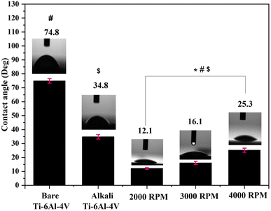
The surface wettability of bare Ti–6Al–4V, AT–Ti–6Al–4V, and Ce-HAP/Fe3O4 composite coatings (2000, 3000, and 4000 rpm) was studied by contact-angle measurement (Fig. 9). Contact angles were obtained due to integration between molecules in the coated surface. The contact angle measured for bare Ti–6Al–4V was 74.8°, and for the alkali-treated specimen it was 34.8°. The water-contact angle for coatings was 12.1°, 16.1°, and 25.3°, respectively, at 2000, 3000, and 4000 rpm. AT-metal displayed a decreased contact angle because of the presence of uniform micropores on the surface. These micropores improved the wettability of the medical-grade AT–Ti–6Al–4V. The contact angle is mainly influenced by the hierarchical structure, such as roughness, chemical composition, surface energy, surface charges, and porosity. The initial viscosity of the material, the density and surface tension of the coating solution, and the specific reactions taking place inside lead to a change in wettability. Furthermore, not all materials are compatible with all surfaces, so they must be chosen depending on the specific characteristics of the target surface, such as surface roughness and texture. Due to an increase in permeability (which was corroborated by SEM), the wettability conductance of Ce-HAP/Fe3O4 composites increased from 2000 to 4000 rpm. By increasing the rpm, the contact angle increased, but there was no significant changes in the contact angle for coatings. The very high hydrophilicity of Ce-HAP/Fe3O4 was due to the presence of hydroxyl groups in HAP and the Fe3O4 nanocomposite. In the case of Fe3O4, the high affinity towards water was due to the cohesive force between hydroxyl groups and water molecules. Increased surface energy or roughness results in a reduced contact angle which, in turn, enhances bone regeneration, cell adhesion, and osteointegration on the implant/tissue interface. Hence, the surface properties relevant to chemical and biological interfaces are required to alter the function of bone healing after implantation.3.8 Vickers micro-hardness
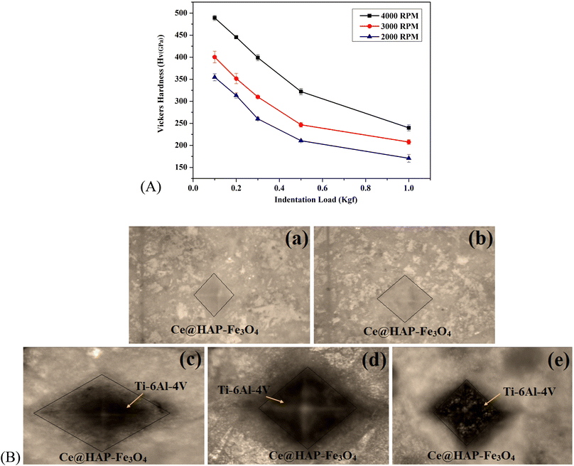
The mechanical properties of the Ce-HAP/Fe3O4 coating were evaluated by the Vickers micro-hardness test. The micro-hardness test provides the internal hardness despite the coating hardness in comparison with the coating/substrate. An indentation load of 0.1 to 10 kgf was applied to the surface of triple-layer coatings. The depth of the indent, magnitude of the force along with dwelling time were noted. Based on the plasticity and elasticity of the material, the micro-hardness was predicted (Fig. 10). The hardness of the coating at 4000 rpm was found to be 489.1 ± 5.7 at an indent load of 0.1 kgf. With an increase in the load, there was a decrease in the micro-hardness. Hence, the applied pressure was inversely proportional to the hardness due to the plastic deformation or plastic strain. Also, the functional group present in HAP, the hydroxyl group (Fe–OH), favors the interfacial force between the metal and coating. As shown in Fig. 10, the hardness values upon incorporation of magnetite material in the HAP matrix likely increased the mechanical property of the material due to hierarchal changes and coating thickness. At higher applied loads, the coating became plastically deformed during the Vickers micro-hardness test. Furthermore, less packing of the composite coating could not withstand higher indentation and led to a decreased hardness value at a high load (1 kgf).The hardness of the composite coating under an applied load of 0.1 kgf at a spin speed of 2000 rpm was 354.5 ± 8.0, at 3000 rpm was 400.4 ± 13.1, and at 4000 rpm was 489.1 ± 5.7 (Table 2). The hardness at 2000 and 3000 rpm decreased due to non-uniformity and voids created on the surface. This was due to the number of defective areas, so a higher applied pressure lowered the hardness. The decrease in the hardness value at 2000 rpm (170.7 ± 8.8), 3000 rpm (207.7 ± 5.3), and 4000 rpm (239.8 ± 6.8) under an applied load of 1 kgf was dependent on the applied force and strength of material that held the coated layer and metal substrate.
| Sample code | Applied load | ||||
|---|---|---|---|---|---|
| 0.1 kgf | 0.2 kgf | 0.3 kgf | 0.5 kgf | 1.0 kgf | |
| 4000 rpm | 489.1 ± 5.7 | 445.4 ± 3.5 | 398.86 ± 6.6 | 321.9 ± 6.8 | 239.8 ± 6.8 |
| 3000 rpm | 400.4 ± 13.1 | 351.03 ± 11.6 | 309.9 ± 3.8 | 246.7 ± 5.1 | 207.7 ± 5.3 |
| 2000 rpm | 354.5 ± 8.0 | 313.2 ± 5.9 | 250.5 ± 3.5 | 210.5 ± 2.4 | 170.7 ± 8.8 |
This result showed that this magnetite material had superior mechanical properties rather than magnetic properties and, hence, could be used in bone applications. The optical microscopy image of the indentation is shown in Fig. 10B. For coatings obtained at 4000 rpm, cracks developed at a higher applied load. Hence, the deformation behavior of coatings differed according to the inner zone and applied load.
3.9 Adhesive strength
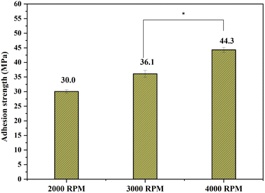
The adhesive strength between the Ce-HAP/Fe3O4 coating on AT–Ti–6Al–4V was investigated based on the pull-off strength. The average bond strength of triple-layer coatings produced at 2000, 3000, and 4000 rpm was 30.0, 36.1, and 44.3 MPa, respectively (Fig. 11).The decrease in bond strength for sample retrieved at 2000 and 3000 rpm was attributed to chemical dissolution in the coatings. This weakening at the interface may have been due to several defects in coatings, and this failure occurred at the lamella across coatings/substrate interfaces. The decrease in bond strength might have been due to a reduction in the interlamellar microstructure of the coatings. This coating produced at 4000 rpm exhibited a higher bond strength (44.3 MPa). The high surface area of this coating appeared to directly enhance the adherence of the deposited Ce-HAP/Fe3O4 film. Physical or chemical bonding contributes to the ability of a coating to adhere to a metallic surface. In this instance, the deposited Ce-HAP/Fe3O4 molecules and species on the alkali-treated Ti surface interacted chemically to form a bond.55,56
The significant increase in the bond strength was due to the chemical affinity of Ti towards the coating. The coating on AT–Ti–6Al–4V using the sol–gel method increased the bond strength due to the microporous structure created on the surface during alkali treatment and passivation of the sol on the implant surface. An unusual property of the Ti surface may be brought about by the presence of OH groups on a treated Ti substrate. For instance, when in contact with a coating, the Ti surface that has been alkali-treated may conduct as a base. Hence, the acidic group-containing Ce-HAP/Fe3O4 film may interact strongly with the Na2TiO3 gel layer. These characteristics make using this method to improve the performance of coatings particularly appealing. Electrostatic forces form at the interface between materials with various electronic band structures, so this type of interaction may strengthen adhesion.57,58 As a result, when the Ce-HAP/Fe3O4 film was deposited on alkali-treated Ti, strong adhesive strength and bonding were observed. The voids and cracks created on the coating affected the bond strength during debonding (2000 and 3000 rpm), which might result in a decrease in the bond strength. Fe3O4 aggregates in the Ce-HAP/Fe3O4 composite occupied pores on the alkali-treated implant surface. This phenomenon led to penetration of the composite material due to formation of a homogenous layer, thereby enhancing the adhesive strength. Numerous technological, constructional, and operational aspects affect the durability of adhesive integration. Constructional aspects include the geometry of the adhesive intersection, the type of joint materials utilized (adhesive and adherents), and the load distribution. A key consideration in the design of a joint is its geometry. The thickness of the adhesive layer is a crucial geometrical parameter.59,60 Hence, our results suggest that the Ce-HAP/Fe3O4 composite coating on AT–Ti–6Al–4V produced at 4000 rpm showed superior adhesive strength that contributed to long-term loadbearing applications.
3.10 Corrosion studies
| Sample descriptions | R s (Ω cm−1) | R ct (Ω cm−1) | C dl (F cm−2) | n | E corr (mV) | I corr (μA cm−2) | β a (mV) | β c (mV) |
|---|---|---|---|---|---|---|---|---|
| Bare Ti–6Al–4V | 12.63 | 6731 | 85 × 10−6 | 0.774 | −112.061 | 2.116 | 241.8 | 168.4 |
| Alkali treated Ti–6Al–4V | 14.48 | 8871 | 69.88 × 10⁻⁶ | 0.768 | −86 | 1.509 | 217.4 | 96.9 |
| 1.25% Ce-HAP 2000 rpm | 75.02 | 73![[thin space (1/6-em)]](https://www.rsc.org/images/entities/char_2009.gif) 828 828 |
18.59 × 10⁻⁶ | 0.752 | −281 | 0.152 | 202.5 | 222.7 |
| 3000 rpm | 19.21 | 181![[thin space (1/6-em)]](https://www.rsc.org/images/entities/char_2009.gif) 090 090 |
28.41 × 10⁻⁶ | 0.730 | −91 | 0.177 | 217.1 | 195.6 |
| 4000 rpm | 50.23 | 241![[thin space (1/6-em)]](https://www.rsc.org/images/entities/char_2009.gif) 040 040 |
1.078 × 10⁻⁶ | 0.809 | −70 | 0.179 | 127.6 | 259.6 |
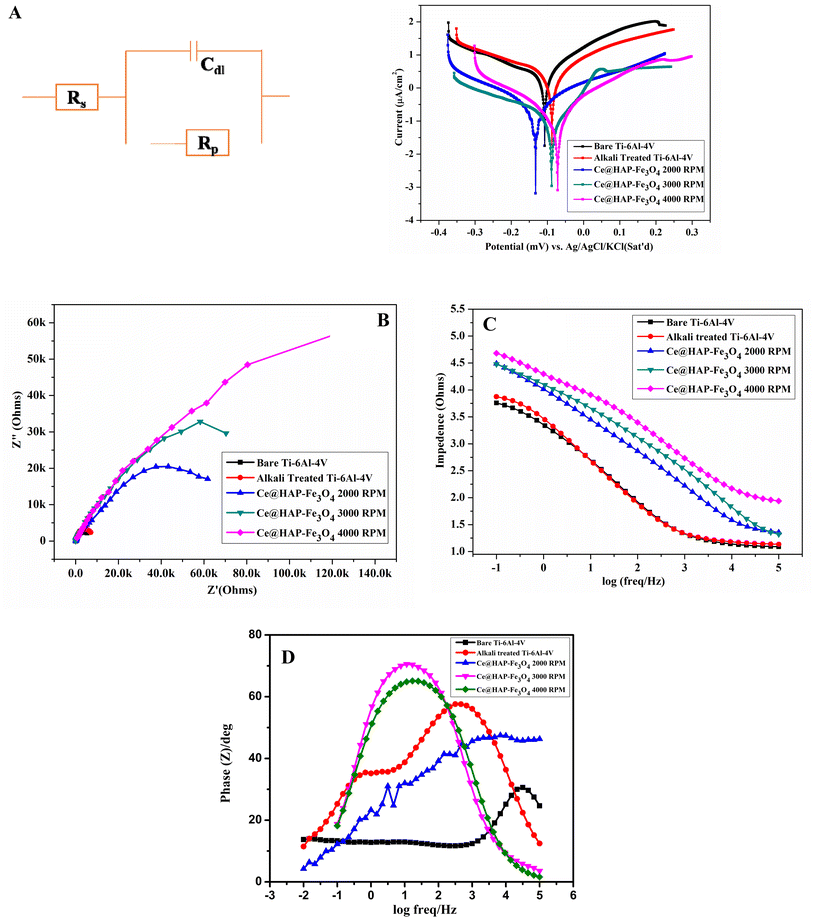
The protective barrier effect of the Ce-HAP/Fe3O4 layer on Ti–6Al–4V increased for the coating at 4000 rpm due to formation of Ce–OH and ferric sulfate/ferric hydroxide film at cathodic and anodic sites. The potential efficiency (PE) of a coating was calculated using the following formula:
| PE = [1 − (Icorr/Io)] × 100 | (4) |
The PE of coatings increased compared with that of Ti–6Al–4V. The PE for 28.69%@AT–Ti–6Al–4V was 92.9% at 2000 rpm, 91.6% at 3000 rpm, and 91.7% at 4000 rpm. The corrosive resistance of the coating increased with increasing rpm. The coating produced at 4000 rpm showed higher PE in SBF compared with all coatings (including bare metal and alkali-treated metal). Cerium and magnetite ions form precipitates on the implant surface. Hence, uniform surface coverage of Ce–OH and ferrite hydroxide reduce corrosion by acting as a protective layer, thus enhancing the corrosion inhibition of a metal coated with a Ce-HAP/Fe3O4 composite film. Therefore, the corrosion remains constant by preventing release of aggressive metal ions at cathodic and anodic sites in SBF solution.
From the Nyquist plot (Fig. 12B), the EIS spectra obtained for bare metal and Ti–6Al–4V showed lower Rct and higher Cd1. This result implied the non-homogeneity and porous nature of the surface. EIS spectra for coated samples revealed higher charge-transfer resistance and, hence, better corrosive resistance of the triple-layer Ce-HAP/Fe3O4 film on the AT–Ti–6Al–4V metal surface. This occurred because the coatings acted as a barrier potential. Hence, they stopped the migration of ions from the electrolyte solution to the metal coating interfaces by preventing corrosion of Ce-HAP. Table 3 reveals that Rct increased for coatings with decreased Cdl, which indicated the higher corrosion resistance of coatings and homogeneity of the surface. The order of good corrosion resistance was bare metal > AT–Ti–6Al–4V > 2000 rpm > 3000 rpm >4000 rpm. Uniform coatings on the Ti surface retard the movement of O2-carrying species, which results in higher corrosion inhibition.61–63
The Bode plot in Fig. 12C reveals that the coatings derived at 4000 rpm exhibited higher impedance at a lower frequency, which indicates better corrosion resistance in SBF solution. For samples produced at 2000 and 3000 rpm, corrosion resistance was found to be less than that at 4000 rpm, which may have been due to thermal mismatch leading to formation of voids and cracks. The diffusion of metal ions is encouraged by voids and cracks, resulting in reduced corrosion potential. The phase angle of all Ce-HAP/Fe3O4 composite coated substrates shifted (Fig. 12D) towards a higher angle at a lower frequency region, which was evidence of an increase in corrosion resistivity in SBF solution. In terms of corrosion, there was a definite difference between 2000, 3000, and 4000 rpm. However, the multilayered coatings produced at 4000 rpm had lower adhesive strength compared with that of the other coatings. As a result, the corrosion resistance obtained from EIS was in accordance with that obtained from polarization studies.
3.11 Antibacterial activity
The antimicrobial efficacy of uncoated and coated surgical implants was evaluated using infection-causing bacteria such as E. coli, P. aeruginosa, Staphylococcus aureus, and Bacillus subtilis (Fig. 13). The survival capacity of the control (without any sample) was 8.26 × 10⁵ for E. coli, 1.00 × 10⁵ for S. aureus, 1.27 × 10⁶ for P. aeruginosa, and 1.24 × 10⁶ CFU ml−1 for B. subtilis. Bare Ti–6Al–4V exhibited a reduced growth rate in contrast with the control. Hence, formation of a TiO2 layer on the Ti–6Al–4V surface may have reduced bacterial growth. However, compared with the control, Ti–6Al–4V showed fewer changes, whereas AT–Ti–6Al–4V displayed considerable reduction in the number of bacteria. Bacterial survival for the Ce-HAP/Fe3O4 composite was reduced compared with bare Ti–6Al–4V and AT–Ti–6Al–4V. The film produced at 4000 rpm was selected for testing of antibacterial activity due to the uniform coating (which was confirmed using various analytical methods). For E. coli, the growth rate was reduced to 6.13 × 10³ CFU ml−1 upon incubation with the Ce-HAP/Fe3O4 composite, whereas S. aureus showed a growth rate of 1.92 × 10⁴ CFU ml−1. The bacterial inhibition of the coated metal showed greater effects towards all bacteria than the bare metal. The order of growth inhibition was E. coli > S. aureus > P. aeruginosa > B. subtilis with respect to the samples bare metal > AT–Ti–6Al–4V > 4000 rpm. With respect to the mechanism of growth inhibition, we proposed that Ce4+ and Fe3+ from the coating reacted with bacteria and disrupt the cell-wall permeability. This action was followed by deactivating the function of cells through binding with the DNA present in nuclei, which caused cell death. Superoxide (O2−) present in cerium was responsible for cell death.65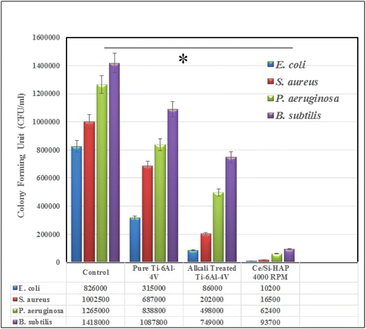 | ||
| Fig. 13 The antibacterial activity of bare Ti–6Al–4V, alkali treated Ti–6Al–4V and Ce-HAP/Fe3O4 composite coating on Ti–6Al–4V against E. coli, S. aureus, P. aeruginosa and B. subtilis pathogens. | ||
The CFU ml−1 values for composite coatings revealed reduced bacterial growth of almost 50% compared with the control. These significant antibacterial effects were observed for Gram-negative bacteria due to the thin outer cell wall containing lipopolysaccharide. Conversely, Gram-positive bacteria displayed less cell growth than P. aeruginosa (Gram-negative bacterium). These unexpected results were due to the thick cell wall of P. aeruginosa, which retards the penetration of Ce4+ and Fe3+ into cells. In case of B. subtilis, the cell wall consists of lipoteichoic acid and peptidoglycans, which endows a negative charge to the cell that prevents diffusion of Ce4+ and Fe3+. These findings revealed the excellent bacterial-growth inhibition, among which the Ce-HAP/Fe3O4 composite coating displayed the best experimental result.
3.12 Morphology of bacterial cells
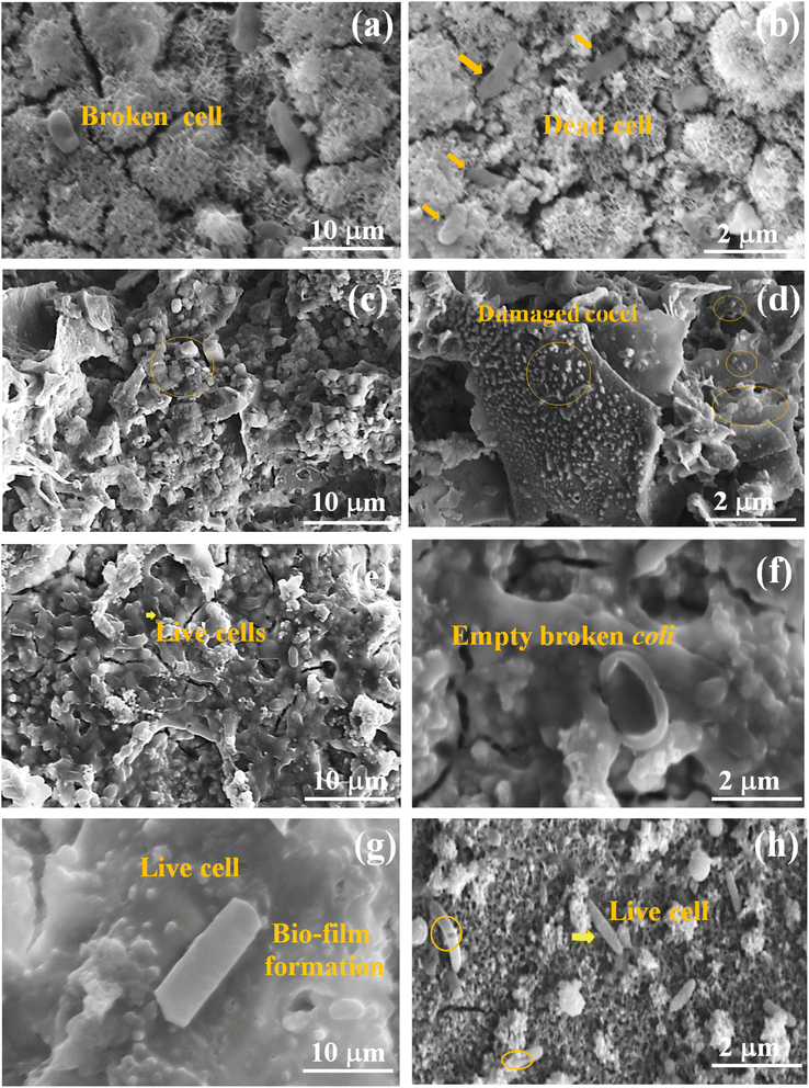
Cell morphology was investigated using SEM (Fig. 14). As seen in Fig. 14a and b, E. coli had normal rod-shaped cells, whereas treated cells had an irregular morphology. After treatment with Ce-HAP/Fe3O4, cells started to rupture and vacuoles were exposed. At 24 h after treatment, all cells had ruptured and bacterial growth was slow. In the case of S. aureus (Fig. 14c and d), all cells were spherical-to-grape-like clusters on the coating. Cells appeared as irregular clusters due to the reaction of the cell with the coating. Fig. 14d shows damaged (shrunken) cells on the coating layer. P. aeruginosa (Fig. 14e and f) had a rod-type structure, and dead cells were broken rods without inner cellular content. At 24 h, the biofilm was reduced and cells were elongated with a broken structure. B. subtilis (Fig. 14g and h) exhibits a rod-like shape with biofilm formation. After treatment, all bacteria exhibited an irregular morphology, with shrunken, broken, empty cells. The impact on the bacterial cell was due to the ions from Ce-HAP/Fe3O4. The bacterial cell wall consists of peptidoglycans that protect cellular content from damage and which transport nutrients. The cell wall of Gram-negative bacteria contain thin peptidoglycans compared with Gram-positive bacteria. Hence, E. coli is more susceptible to death than S. aureus. In the case of P. aeruginosa (Gram-negative bacteria), the cell wall contains the protein f-factor, which restricts the interaction of ions with the cell membrane, and leads to biofilm formation (Fig. 14e and f). Among bacterial cells, physiological differences affect inhibitory effects, which influences biofilm formation in case of B. subtilis and P. aeruginosa.Cerium and magnetite ions kill bacterial cells by destroying the outer cell membrane by electrostatic attraction with ROS created by cerium and Fe3O4, and penetrate through the cell membrane. These ions (cerium and magnetite) bind with intracellular amino acids and proteases, leading to protein denaturation and modification of enzyme functions. Cerium and magnetite ions hamper DNA replication and cause cell death. Cerium and Fe3O4 disrupted the cellular function of microbes thanks to their bactericidal activity. The Ce-HAP/Fe3O4 composite coating showed resistance against bacteria. The change in the surface topography of coatings was due to PBS, which enhanced the bioactivity and increased the bacterial resistance of the coatings.
3.13 Cytotoxicity
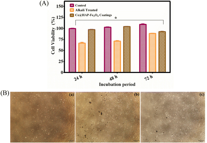
An in vitro cytotoxicity study is an important criterion to test the compatibility of materials in biomedical application. Considering the toxicity of Fe3O4 NPs and Ce-HAP/Fe3O4 films, the MTT assay was carried out using human osteoblast-like cells (MG-63) (Fig. 15). The viability of MG-63 cells on composite coatings was enhanced, and proliferation of 93.96%, 97.19%, and 103% was noted from 24, 48, and 72 h, respectively. The enhanced cell viability of the Ce-HAP/Fe3O4 composite film was due to the incorporation of Ce4+ in HAP and Fe3O4, which were non-toxic. Compared with control and alkali-treated AT–Ti–6Al–4V (non-coated), the cell viability increased for coatings. This finding confirmed that the presence of Fe3O4 in the composite coating did not influence the viability of MG-63 cells. The phase-contrast microscopy (Fig. 15B) result was in good agreement with the percent cell viability: cell morphology was unaffected. The direct contact of cells with the non-homogeneous ferrous AT–Ti–6Al–4V substrate led to excellent viability for uniform homogeneous composite coatings after long-term exposure. The release of calcium and cerium into the culture medium could support the growth and division of cells by increasing the activity of cells through gene activation.Strong magnetic characteristics and distinctive superparamagnetic characteristics are present in NPs composed of Fe3O4 at the nanometer scale. Cell membranes, meanwhile, have a complicated structure. In addition to charged lipid molecules, water, and proteins, they also have many ion channels, including K+, Na+, Ca2+, and others. The inner and outer surfaces of membrane also contain significant concentrations of Cl−, K+, Na+, and other anions and cations.66,67 Due to the contrast in internal and exterior ions and charges, Fe3O4 NPs can act as magnetic sources in the weak electromagnetic field created by the cell, thereby delivering a biological effect on the magnetic field in cells.68 Ajeesh et al. (2010) studied the non-toxic nature of Fe3O4/HAP. They showed that 40% of Fe3O4/HAP was non-toxic to human osteoblast cell lines.69 Hence, coatings with Fe3O4 nanocomposites improved the biocompatibility of MG-63 cells due to the presence of calcium and cerium. Therefore, coatings with Fe3O4 nanocomposites could be promising materials for bone regeneration.
3.14 Cell morphology
The morphology of MG-63 cells and their adhesion on Ce-HAP/Fe3O4 composite coatings were analyzed using SEM (Fig. 16). At 24 h of culture, cellular morphology was a flattened spindle-to-ellipsoidal shape and uniformly distributed on the coatings. At 48 h of culture, cells showed a petal-like structure connected to each other (cell-to-cell communication) with increased proliferation of cells. All cells attached firmly onto the surface. At 72 h of cell culture (Fig. 16e and f), cells were spheroids with filopodia and lamellipodia extension in the nanometer range. The ellipsoidal structure of spheroids with stretching is shown in Fig. 16f. Pseudopod extension favors the anchoring of cells on the coated surface. The spheroid structure observed at 72 h of culture indicated the involvement of MG-63 cells in division. Cells exhibited a spindle-to-spheroid shape with numerous cells in contact, which indicated superior adhesion and growth with respect to the incubation period. Cell proliferation increased due to the large number of cells attached on the Ce-HAP/Fe3O4 composite coating, which indicated that surface chemistry and topography had fundamental roles in the adhesion and proliferation of cells. Release of Ce, Ca, and Fe ions from coatings led to alteration of pH. This phenomenon led to alteration of transmembrane proteins (e.g., fibronectin and vitronectin) by exchange of Ca2+ and H+ across the cell membrane. Upon cell culture, these proteins were readily adsorbed on the Ce-HAP/Fe3O4 coating, consequently promoting cell growth. Surface roughness and increased surface area influenced cellular activity by increasing protein adsorption on the composite coating. As a result, magnetic material did not show any negative effects on MG-63 cells. Therefore, these findings suggested that the Ce-HAP/Fe3O4 coating enhanced osteogenic proliferation and adhesion for bone-tissue regeneration.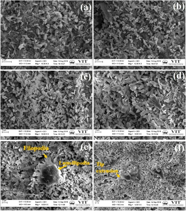 | ||
| Fig. 16 Adhesion and cell morphology of MG-63 cells on Ce-HAP/Fe3O4 composite coatings produced at 4000 rpm for 24 h (a and b),48 h (c and d) and 72 h (e and f). | ||
3.15 Living and dead cells
The MTT assay can be employed to predict the reduction in mitochondrial activity of cells, which does not denote cellular death. Hence, viability was confirmed by apoptosis and necrosis assays. AO/EB fluorescent staining can be used to discriminate living and dead cells simultaneously. It can distinguish normal cells from cells undergoing early–late apoptosis or necrosis. This assay was done on the Ce-HAP/Fe3O4 composite film and quantified using MG-63 cells (Fig. 17). In AO staining, green fluorescence denotes normal cells; AO bonds to the DNA in intact cell membranes. EB staining leads to emission of orange–red fluorescence. EB interacts only with dead or damaged cells. At 24 h of culture, there was no substantial difference compared with the control (Fig. 17). Increasing the incubation period led to early apoptosis and bright-green-to-yellow nuclei were observed (Fig. 17). The number of late-apoptotic stages increased with an increased exposure period. However, the number of apoptotic cells was low and no sign of necrotic cells appeared throughout this process. The appearance of early- and late-apoptosis was due to the release of cerium and iron ions into medium, which caused the apoptosis of some cells and some nuclear damage. Yuan et al. (1998) developed a Fe3O4-HAP magnetic scaffold (core–shell) iron oxide/HAP and demonstrated its biocompatibility using MG-63 cells.70Therefore, living/dead cell assay using AO/EB staining showed that the Ce-HAP/Fe3O4 composite film was non-toxic, and more living cells than dead cells were observed. Hence, MG-63 cells were affected by magnetic particles and Ce-HAP/Fe3O4 supported the growth of osteoblast-like cells.
3.16 Staining
To evaluate nuclear morphology, MG-63 cells were cultured on Ce-HAP/Fe3O4 and stained with propidium iodide (Fig. 17B). Staining with propidium iodide lead to bright-red cells. Apoptosis detection through assessment of nuclear morphology emphasizes chromatin condensation for early apoptosis and nuclear shrinkage and formation of apoptosis debris for late-stage apoptosis. In the control group, cells were elliptical with a normal nucleus stained with red fluorescence. At 24 h of treatment, cells did not show morphological changes. Cells treated with coating for 24 or 48 h did not show discernible nuclear changes or chromatin condensation. At 72 h of treatment, cells showed a bright-red nucleus with chromatin condensation, which was illustrated by deformed, convoluted, and disarranged nuclei. A deformed nuclear structure was observed at 72 h of treatment with Ce-HAP/Fe3O4 coatings. However, the number of nuclear condensations or change in nuclear structure was less compared with normal cells. These result suggested that the biochemical changes in cells due to the presence of Fe3O4 and cerium in the coating may cause transient increases in apoptosis.These results were good agreement with the AO/EB staining where the cells displayed apoptosis at 72 h of treatment. Both the staining suggests the number of normal cells were higher than the deformed cells. The present study demonstrates the Ce-HAP/Fe3O4 coating were not harmful to osteoblast and hence it can serve an orthopedic implant in the field of biomedical applications.
3.17 Heating efficiency of coatings
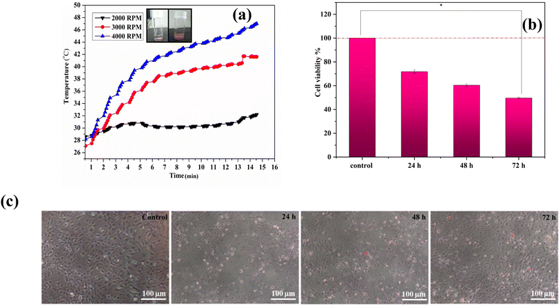
A schematic representation of for removal of osteosarcoma cells and replacement with Ce-HAP/Fe3O4–Ti–6Al–4V is given in Fig. 18. The heating efficiency of composite coatings was evaluated by hyperthermia treatment. The heating curves obtained by various coatings are displayed in Fig. 19a. The heating capacity was greater for Ce-HAP/Fe3O4@4000 rpm, which could generate 47 °C in 15 min. In general, 40°45 °C is a tolerable temperature for cancer treatment, with a minimum magnetite content of 5%. Anomalous heating was observed for composite coatings (Fig. 19b). The heating rate of Ce-HAP/Fe3O4@4000 rpm was higher than that of Ce-HAP/Fe3O4@2000 rpm. The heating efficiency of Ce-HAP/Fe3O4@3000 rpm was higher than that for Ce-HAP/Fe3O4@2000 rpm at an identical concentration of Fe. This poor heating behavior was due to the colloidal stability of composite coatings. A heating temperature of 45 °C was sufficient to trigger the apoptosis of cancer cells and provide treatment for bone cancer as well bone defects.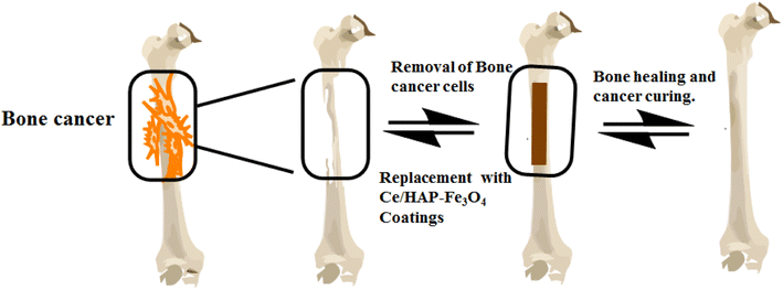 | ||
| Fig. 18 Schematic representation of bone cancer therapy by removal of osteosarcoma cells and replacement with Ce-HAP/Fe3O4–Ti–6Al–4V. | ||
3.18 In vitro hyperthermia treatment
Hyperthermia treatment can kill cancer cells by inhibiting DNA replication, altering cellular minerals, preventing cell division (by cell-cycle arrest) and, finally, causes cell death (apoptosis). An in vitro hyperthermia experiment was conducted using human osteosarcoma (Saos-2) cells, and cell viability is depicted in Fig. 19c. Osteosarcoma is a rare malignant bone cancer. Saos-2 cells contain a bone-mineralization component in their extracellular matrix. Saos-2 was used as a model cell line that produces various stages of osteogenic differentiation. Cells exposed to hyperthermia treatment were compared with control cells (100% viability). There was reduction in cell viability of 71.76%, 60.40%, and 49.60% with respect to incubation periods of 24, 48, and 72 h, respectively. Greater effects on cell viability were observed for cells incubated for 72 h. Morphological changes of cells were observed under an optical microscope. Compared with the control, Ce-HAP/Fe3O4 coatings induced the death of significant numbers of cells. Cells were shrunken due to hyperthermia therapy.The loss of the tumor-cell viability was attributed to the physical damage to cells caused by magnetic heating which, in turn, killed them. Apoptosis and necrosis of cells were determined by staining with propidium iodide. The apoptotic bodies enclosed in cellular components resulted from physicochemical and morphological changes. The discharge of intracellular components through osmotic swelling resulted in necrosis. Hyperthermia induced increased cellular permeability with intrinsic apoptosis (Fig. 20). At 24 h of incubation, cells were not very permeable. At 72 h, cells had an orange pigmentation because necrosis occurred with alteration of cell shape by nuclear splitting. Heat induced cells to show increased permeability. This rapid increase in cell permeability denoted apoptosis. Hyperthermia induced heat shock on Saos-2 cells. Hence, a coating prepared with a combination of magnetite composites could be used for cancer therapy.
4 Conclusions
Four main conclusions were drawn from out study.• Magnetite material was impregnated with cerium-doped HAP by a sol–gel method. The resultant sol was used for spin-coating. A Ce-doped HAP/Fe3O4 composite coating was fabricated on surgical-grade Ti–6Al–4V alloy. The physicochemical properties of coatings (morphology, thickness and composition) were controlled by the spin rate. Magnetite NPs imparted with a magnetic property exhibited a rough uniform surface at 4000 rpm with a significant hydrophilic property.
• The thin-film coating exhibited an architecture of 80 μm thickness with a stack of layers and micromechanical properties. Upon inclusion of magnetite NPs, the adhesive strength and hardness increased. It showed improved corrosion resistance with enhanced biomineralization that could enable its use in bone tissue-to-coating/substrate bonding after implantation.
• The viability and proliferation of MG-63 osteoblasts on the Ce-HAP/Fe3O4 film were nontoxic. This coating demonstrated excellent activity against various Gram-negative and Gram-positive bacteria.
• Coatings with the Fe3O4 composite could enhance bone-cell proliferation. Hyperthermia could be used to treat bone defects. Also, 47 °C was an ideal temperature to kill tumor cells.
• Ce-HAP/Fe3O4 shows excellent effects in term of biomineralization, antibacterial activity, corrosion resistance, osteoblast proliferation, and hyperthermia treatment.
• Ce-HAP/Fe3O4 could be optimized as an implant for advanced bone regeneration and healthcare products.
Conflicts of interest
There are no conflicts to declare.Acknowledgements
Dr U. Vijayalakshmi acknowledges the DST, New Delhi, India (EMR/2016/002542) for providing financial support. The authors acknowledge the Vellore Institute of Technology (Vellore, India) for rendering the necessary facility vide seed project SG20220035. Dr B. Priyadarshini thanks DBT for the award of Research Associate (DBT-RA/2023/January/N/3756).References
- K. Prasad, O. Bazaka, M. Chua, M. Rochford, L. Fedrick, J. Spoor, R. Symes, M. Tieppo, C. Collins and A. Cao, Materials, 2017, 10(8), 884 CrossRef PubMed.
- G. Manivasagam, D. Dhinasekaran and A. Rajamanickam, Recent Pat. Corros. Sci., 2010, 2, 40–54 CrossRef CAS.
- H. J. Rack and J. I. Qazi, Mater. Sci. Eng., C, 2006, 26, 1269–1277 CrossRef CAS.
- A. Udduttula, J. Li, Z. Ma, B. Teng, J. V. Zhang, A. M. Ferreira, P. Gentile, G. Wang, X. Zhao and P. G. Ren, Ceram. Int., 2022, 48, 10979–10989 CrossRef CAS.
- X. Liu, P. K. Chu and C. Ding, Mater. Sci. Eng., R, 2004, 47(3–4), 49–121 CrossRef.
- G. Gabarró-Riera, G. Aromí and E. C. Sañudo, Coord. Chem. Rev., 2023, 475, 214858 CrossRef.
- L. E. Scriven, MRS Online Proc. Libr., 1988, 121, 717 CrossRef CAS.
- A. Nanci, J. D. Wuest, L. Peru, P. Brunet, V. Sharma, S. Zalzal and M. D. McKee, J. Biomed. Mater. Res., Part A, 1998, 40(2), 324–335 CrossRef CAS.
- H. B. Wen, J. G. C. Wolke, J. R. De Wijn, Q. Liu, F. Z. Cui and K. De Groot, Biomaterials, 1997, 18(22), 1471–1478 CrossRef CAS PubMed.
- R. I. M. Asri, W. S. W. Harun, M. A. Hassan, S. A. C. Ghani and Z. Buyong, J. Mech. Behav. Biomed. Mater., 2016, 57, 95–108 CrossRef CAS PubMed.
- U. Vijayalakshmi, K. Prabakaran and S. Rajeswari, J. Biomed. Mater. Res., Part A, 2008, 87(3), 739–749 CrossRef CAS PubMed.
- L. Duta and C. P. Andrei, Coat, 2019, 9, 335 CrossRef CAS.
- M. L. Zheludkevich, I. Miranda Salvado and M. G. S. Ferreira, J. Mater. Chem., 2005, 15, 5099–5111 RSC.
- G. Fernandez de Grado, L. Keller, Y. Idoux-Gillet, Q. Wagner, A. M. Musset, N. Benkirane-Jessel, F. Bornert and D. Offner, J. Tissue Eng., 2018, 9, 2041731418776819 Search PubMed.
- C. Cunha, S. Sprio, S. Panseri, M. Dapporto, M. Marcacci and A. Tampieri, J. Biomed. Mater. Res., Part A, 2013, 101(6), 1612–1619 CrossRef PubMed.
- H. Huang, Y. Manga and W. N. Huang WN, Mater, 2018, 11, 1897 CrossRef PubMed.
- T. J. Webster, C. Ergun, R. H. Doremus and R. Bizios, J. Biomed. Mater. Res., 2002, 59(2), 312–317 CrossRef CAS PubMed.
- J. S. Al-Sanabani, A. A. Madfa and F. A. Al-Sanabani, Int. J. Biomater., 2013, 876132 Search PubMed.
- W. S. W. Harun, R. I. M. Asri and A. Bakar Sulong A., Hydroxyapatite - Advances in Composite Nanomaterials, Biomedical Applications and its Technological Facets, 2018, vol. 69, DOI:10.5772/intechopen.71063.
- R. Drevet, N. B. Jaber, J. Faure, A. Tara, A. B. Larbi and H. Benhayoune, Surf. Coat. Technol., 2016, 301, 94–99 CrossRef CAS.
- B. Priyadarshini and U. Vijayalakshmi, Adv. Powder Technol., 2018, 29(11), 2792–2803 CrossRef CAS.
- D. Gopi, S. Sathishkumar, A. Karthika and L. Kavitha, Ind. Eng. Chem. Res., 2014, 53(52), 20145–20153 CrossRef CAS.
- D. B. Mathi, R. Karthika, A. B. Priya, A. Mydhili, D. Gopi and L. Kavitha, Adv. Nat. Appl. Sci., 2017, 11(8), 111–116 CAS.
- G. Ciobanu, A. M. Bargan and C. Luca, Ceram. Int., 2015, 41(9), 12192–12201 CrossRef CAS.
- R. Banerjee, Y. Katsenovich, L. Lagos, M. McIintosh, X. Zhang and C. Z. Li, Curr. Med. Chem., 2010, 17(27), 3120–3141 CrossRef CAS PubMed.
- P. Baskaran, A. Udduttula and V. Uthirapathy, IET Nanobiotechnol., 2018, 12(2), 138–146 CrossRef.
- N. Tran and T. J. Webster, J. Mater. Chem., 2010, 20(40), 8760–8767 RSC.
- C. Sun, K. Du, C. Fang, N. Bhattarai, O. Veiseh, F. Kievit, Z. Stephen, D. Lee, R. G. Ellenbogen, B. Ratner and M. Zhang, ACS Nano, 2010, 4(4), 2402–2410 CrossRef CAS PubMed.
- R. Weissleder, D. D. Stark, B. L. Engelstad, B. R. Bacon, C. C. Compton, D. L. White, P. Jacobs and J. LewiS, AJR, Am. J. Roentgenol., 1989, 152(1), 167–173 CrossRef CAS PubMed.
- Z. R. Stephen, P. A. Chiarelli, R. A. Revia, K. Wang, F. Kievit, C. Dayringer, M. Jeon, R. Ellenbogen and M. Zhang, Cancer Res., 2019, 79(18), 4776–4786 CrossRef PubMed.
- A. V. Samrot, K. S. Bhavya, J. L. Angalene, S. M. Roshini, R. Preethi, S. M. Steffi, P. Raji and S. S. Kumar, Int. J. Biol. Macromol., 2020, 15(153), 1024–1034 CrossRef PubMed.
- J. K. Patra, G. Das, L. F. Fraceto, E. V. R. Campos, M. Del Pilar Rodriguez-Torres, L. S. Acosta-Torres, L. A. Diaz-Torres, R. Grillo, M. K. Swamy and S. Sharma, J. Nanobiotechnol., 2018, 16(1), 71 CrossRef PubMed.
- Y. Weng, J. Chen, Q. Tu, Q. Li, M. F. Maitz and N. Huang, Interface Focus, 2012, 2(3), 356–365 CrossRef PubMed.
- O. I. Nakonechna, G. S. Lotey, A. K. Tangra, S. Singh, A. V. Bodnaruk, V. O. Zamorskyi, N. N. Belyavina, I. V. Sharay and A. I. Tovstolytkin, J. Magn. Magn. Mater., 2021, 540, 68452 CrossRef.
- A. Vedrtnam, K. Kalauni, S. Dubeyand and A. Kumar, AIMS Mater. Sci., 2020, 7(6), 800–835 CAS.
- Y. Wu, W. Jiang, X. Wen, B. He, X. Zeng, G. Wang and Z. Gu, Biomed. Mater., 2010, 5(1), 15001 CrossRef PubMed.
- U. Anjaneyulu and U. Vijayalakshmi, Mater. Lett., 2017, 189, 118–121 CrossRef CAS.
- S. Singh, G. Singh and N. Bala, Mater. Chem. Phys., 2019, 237, 121884 CrossRef CAS.
- R. A. Revia and M. Zhang, Mater. Today, 2016, 19(3), 157–168 CrossRef CAS PubMed.
- K. M. Krishnan, IEEE Trans. Magn., 2018, 46(7), 2523–2558 Search PubMed.
- U. Anjaneyulu, B. Priyadarshini, S. Arul Xavier Stango, M. Chellappa, M. Geetha and U. Vijayalakshmi, Mater. Technol., 2017, 32(13), 800–814 CrossRef CAS.
- K. J. Baeg, M. Caironi and Y. Y. Noh, Adv. Mater., 2013, 25, 4210–4244 CrossRef CAS PubMed.
- B. Kang, W. H. Lee and K. Cho, ACS Appl. Mater. Interfaces, 2013, 5, 2302–2315 CrossRef CAS PubMed.
- M. Campoy-Quiles, Nat. Mater., 2008, 7, 158–164 CrossRef CAS PubMed.
- S. Kim, RSC Adv., 2014, 4, 41159–41163 RSC.
- J. Li, Sci. Rep., 2012, 2, 754–762 CrossRef PubMed.
- H. Sirringhaus, Nature, 1999, 401, 685–688 CrossRef CAS.
- S. R. Forrest, Nature, 2004, 428, 911–918 CrossRef CAS PubMed.
- H. Yan, Nature, 2009, 457, 679–686. CrossRef CAS PubMed.
- J. Soeda, Adv. Mater., 2014, 26, 6430–6435 CrossRef CAS PubMed.
- D. D. Deligianni, N. D. Katsala, P. G. Koutsoukos and Y. F. Missirlis, Biomater, 2000, 22(1), 87–96 CrossRef PubMed.
- B. Priyadarshini, S. Ramya, E. Shinyjoy, L. Kavitha, D. Gopi and U. Vijayalakshmi, J. Mater. Res. Technol., 2021, 12, 1319–1338 CrossRef CAS.
- P. Tian, X. Zhao, B. Sun, H. Cao, Y. Zhao, J. Yan, Y. Xue, H. Lin, S. Han, T. Ren and C. Wang, Surf. Coat. Technol., 2022, 433, 128118 CrossRef CAS.
- S. Singh, G. Singh, N. Bala and K. Aggarwal, Int. J. Biol. Macromol., 2020, 151, 519–528 CrossRef CAS PubMed.
- A. Abdal-hay, K. Gulati, T. Fernandez-Medina, M. Qian and S. Ivanovski, Appl. Surf. Sci., 2020, 505, 144604 CrossRef CAS.
- D. J. Alner, Aspect of Adhesion, University of London Press, London, UK, 1965 Search PubMed.
- H. Winter, Fertigungstechnik von Luft- und Raumfahrzeugen, Springer, Berlin/Heidelberg, Germany, 1967 Search PubMed.
- W. Li, J. Li and Y. Xu, Coatings, 2021, 11, 960 CrossRef CAS.
- L. Bartels, Nat. Chem., 2010, 2(2), 87–95 CrossRef CAS PubMed.
- J. J. Gooding and S. Ciampi, Chem. Soc. Rev., 2011, 40(5), 2704–2718 RSC.
- S. A. X. Stango and U. Vijayalakshmi, Ceram. Int., 2019, 45(1), 69–81 CrossRef.
- H. Bakhtiari-Zamani, E. Saebnoori, H. R. Bakhsheshi-Rad and F. Berto, Materials, 2022, 15(23), 8300 CrossRef CAS PubMed.
- H. R. Bakhsheshi-Rad, E. Hamzah, M. Daroonparvar, R. Ebrahimi-Kahrizsangi and M. Medraj, Ceram. Int., 2014, 40(6), 797179–797182 CrossRef.
- M. Rahimi-Nasrabadi, M. Behpour, A. Sobhani-Nasab and S. Hosseinpour-Mashkani, J. Mater. Sci.: Mater. Electron., 2015, 26(12), 9776–9781 CrossRef CAS.
- H. R. Bakhsheshi-Rad, E. Hamzah, A. F Ismail, M. Aziz, M. Daroonparvar, E. Saebnoori and A. Chami, Surf. Coat. Technol., 2018, 334, 450–460 CrossRef CAS.
- M. Blank, Electromagn. Biol. Med., 2008, 27, 3 CrossRef CAS PubMed.
- M. Cifra, J. Z. Fields and A. Farhadi., Prog. Biophys. Mol. Biol., 2011, 105, 223–246 CrossRef CAS PubMed.
- T. Ikehara, H. Yamaguchi and H. Miyamoto, J. Med. Invest., 1998, 45, 47–56 CAS.
- M. Ajeesh, B. F. Francis, J. Annie and P. R. H. Varma, J. Mater. Sci.: Mater. Med., 2010, 21(5), 1427–1434 CrossRef CAS PubMed.
- H. Yuan, P. Zou, Z. Yang, X. Zhang, J. D. De Bruijn and K. De Groot, J. Mater. Sci.: Mater. Med., 1998, 9(12), 717–721 CrossRef CAS PubMed.
| This journal is © The Royal Society of Chemistry 2023 |

