A novel electric stimulus-responsive micro-actuator for powerful biomimetic motions†
Ruide
Yun
 *,
Jingyu
Che
,
Zhiwei
Liu
,
Xiaojun
Yan
and
Mingjing
Qi
*
School of Energy and Power Engineering, Beihang University, Beijing, China. E-mail: ruideyun@buaa.edu.cn; qimingjing@buaa.edu.cn
First published on 10th July 2023
Abstract
Limited by the surface-to-volume ratio of structural materials, it is a great challenge to achieve high output performance in a millimetre-sized actuator. Traditional rigid actuators can achieve higher vibration frequencies above the centimetre size, but their working performance will be greatly reduced below the millimetre size, and even cannot maintain the vibration. A micro-actuator is highly essential for the miniaturisation of bionic robots. In this work, we present a novel driving principle by utilising the plasmonic thermal energy generated by electric stimulation to drive the vibration of the micro-actuator. In the design, the micro-actuator is composed of two chambers and elastic elements, which is similar to the design of a micro-piston. By utilising the thermal energy of the plasma, the actuator can generate high-frequency vibration (resonant frequency of 140 Hz), and the simple structural design can achieve a large vibration amplitude on a millimetre scale. Based on this powerful actuator, several applications are presented, such as fast crawling and jumping. The good performance of the electric stimulus-responsive micro-actuator suggests promising applications ranging from millimetre-scale robots in confined spaces to detection, search and rescue.
Introduction
Small creatures in nature have powerful crawling, jumping, or flying mobility, which is affected by the reaction between predator and prey.1,2 Animal locomotion may provide biologically relevant insight into robot motion,3–5 such as grabbing,6–8 crawling,9,10 and jumping.1 In bio-inspired robotics, soft actuators play an important role due to their ability to handle deformable and fragile objects and adapt to irregular shapes.11 These soft micro-actuators are generally fabricated using dielectric elastomers (DE),12 shape memory alloys (SMA),13 hydrogels,14 and liquid crystal elastomers.15 Dielectric elastomers (DE) can present a large response force, rapid reaction, and high energy density under external electric stimulation,12,16 and a change in the shape of synthetic polymers and gels can be induced by the application of temperature, electric fields, or chemicals.17–19 In addition, some soft actuators can achieve promising stimulus-responsiveness under changing environmental conditions.3 Soft actuators have better flexibility and adaptability and are gradually becoming one of the most attractive areas,20–22 exhibiting more promising research in the fields of biomimetic locomotion, grippers, healthcare, wearable devices, manufacturing, and robotics. Currently, in robotics, soft actuators are widely used for the biomimetic locomotion of robots. However, they is difficult to use to achieve fast drive movements for soft robots16,23,24 due to the determination and limitation of the material physical properties on the specificity of the response.19Compared to soft actuators, some rigid actuators exhibit superior output performance in micro-robotics applications, despite losing their physically flexible body structure. These rigid actuators possess high resonant frequencies, large deflection, and significant reaction forces. Piezoelectric actuators,25 magnetic actuators,26 and electrostatic actuators4 are some typical examples of rigid actuators that have shown great ability in the motions of crawling,27–30 jumping,5,31–33 and flying.34–36 However, these actuators are typically limited to centimetre-sized robots, as achieving high energy efficiency with favourable physical scaling becomes a significant challenge as the size of the actuators decreases.37,38
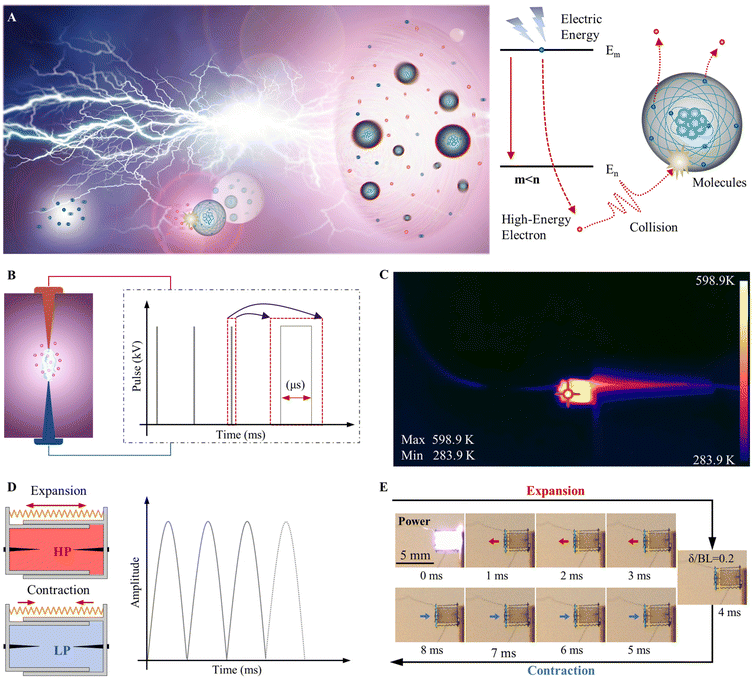
In order to overcome the lack of output power in millimetre-sized actuators, in this work we have proposed a novel electric stimulus-responsive micro-actuator, which has a chamber to expand under the action of plasmonic thermal energy. As depicted in Fig. 1(A), upon being stimulated by an electric field, the electrons in the lower levels of the molecule gain energy and are converted into high-energy electrons. Once the energy acquired by the electrons fits the energy level of the leap, the electrons will leave their previous energy-level orbits. The electrons in the excited state will, in turn, collide with other molecules to excite even more high-energy particles, leading to an electron avalanche. A large amount of energy is released during this process. This form of plasmonic thermal energy can be applied to drive the millimetre-sized actuator to produce a potent output.
In our previous studies,5 we conducted experiments that demonstrated the impressive driving capability of electrical pulsed micro-actuators. In this work, we further study and measure the operation characteristics of the micro-actuators, such as the temperature field, vibration frequency, electric power, and energy efficiency. The operating mechanism and output performance of the actuator are analysed in detail from the dynamic model and experiment. In addition, application of the novel micro-actuator will be explored and discussed by comparing it with existing micro-actuators or biological animals.
Results and discussion
Working principles of the micro-actuator
During the generation of the plasma, we adopted a pulsed signal as the electric stimulation, as shown in Fig. 1(B). The temperature of the actuator during the vibration was recorded using infrared thermometers (FLUKE TIS60+), as shown in Fig. 1(C), where the maximum temperature of the actuator chamber was recorded at 598.9 K for plasma-generating heat and 283.9 K for ambient room temperature. Once the electric pulse signal excites the plasma to generate an arc, the released thermal energy increases the pressure in the chamber, allowing the actuator chamber to expand and perform work. Constrained by the elastic elements, the chamber then contracts back to complete a cycle of vibration. As pictured in Fig. 1(D), the vibration amplitude of the actuator is a sinusoidal function within a half cycle and the vibration frequency is related to the stimulation frequency of the pulse signal. The captured real vibration process is shown in Fig. 1(E) and Movie S1,† where the micro-actuator is powered by a 4 kV electric signal with a pulse width of 1 μs (high-voltage pulse generator, HVP-B10K/IRE). After being stimulated by a pulsed electric signal, the micro-actuator exhibits an expansion movement followed by a contraction movement, completing a vibration cycle, where the frequencies of the electric pulse signal and the actuator vibration are both 120 Hz. The detailed vibration output characteristics are discussed in the following section.Effect of the electric signal on plasma temperature
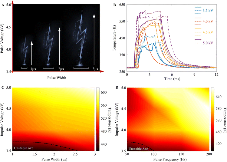
In the system, the electric signal affects the thermal energy carried by plasma in the micro-actuator chamber, where the pulse voltage amplitude and width are two essential parameters that determine the energy introduced into the system. In the test, the amplitude of the stimulation voltage was set to vary from 3.5 kV to 5 kV with an interval of 0.5 kV, and the pulse width was set to vary from 1 μs to 3 μs, as shown in Fig. 2(A). Three identical micro-actuators were fabricated and tested separately under the same conditions. Temperature changes in the actuator chamber were recorded in the all-time domain using an infrared thermometer. The changing temperature of the micro-actuator after an electric stimulation is shown in Fig. 2(B). As the stimulation voltage increases, the temperature inside the actuator chamber rises.In addition, we have investigated the interactive contribution of pulse voltage amplitude and pulse width to the temperature variation of the micro-actuator. As shown in Fig. 2(C), the maximum temperature of 613.8 K occurs when a pulse voltage of 5 kV with a width of 3 μs is applied. At the same 5 kV pulse voltage, the temperature of the micro-actuator chamber decreases by less than 1% when the pulse width is reduced to 2 μs. In the test, the actuator chamber generates a stable high temperature under pulsed signal stimulation when the voltage amplitude is higher than 3.5 kV and the pulse width is longer than 2 μs. Otherwise, the unstable arc will reduce the thermal effect of the plasma. In future applications, the micro-actuator should be kept from being stimulated by undesirable electric signals to achieve a reliable thermal output.
The frequency of the electric pulse determines how much energy is introduced into the actuator per unit of time, which is also critical to the operating state of the actuator. In Fig. 2(D), the effect of the stimulation frequency on the temperature of the actuator chamber is illustrated at different voltages, where the maximum temperature of 686.4 K appears at a pulse frequency of 200 Hz and a voltage of 4.5 kV. As the voltage and frequency increase, the temperature of the actuator chamber increases linearly.
Materials and preparation for the micro-actuator
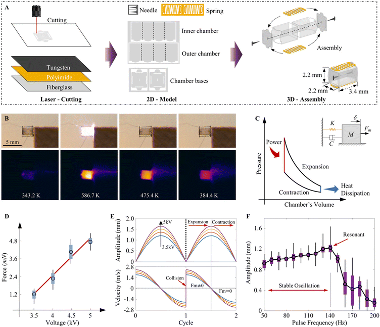
To enable the good operation of a micro-actuator, fabrication is the critical step, especially for millimetre-sized actuators, where the manufacturing accuracy must be on the order of micro or even nano. In addition, the materials of the actuator need to satisfy the characteristics of high-temperature resistance, good insulation, low thermal resistance and high strength; in particular, the electrode material must be resistant to high temperature and electric erosion. In the fabrication of the micro-actuator, we have selected fibreglass plates (thickness 0.1 mm) as the material for the actuator chamber, tungsten plates (0.05 mm) for the electrode and polyimide film (0.05 mm) for the elastic element. To reduce processing errors, all materials are cut using a laser (HANS LASER EP-15-THG-S, cutting accuracy of 20 nm) for greater fabrication accuracy. As shown in Fig. 3(A), the cut two-dimensional structures are changed into a three-dimensional model using the origami method,39 and the assembly is further completed using the positioning holes and the mortise and tenon structure. A clearance fit of 0.01 mm is used in mortise and tenon machining to accommodate the positioning of the installation. The cumulative assembly error of the actuator is controlled to be within 0.02 mm. All assembly processes are performed in the micromechanical testing system (FT-MAT02, Femto Tools, Germany) for higher assembly accuracy. In addition, to reduce the friction between the inner and outer chambers of the actuator, a clearance allowance of 0.1 mm is set in the structural design. Through numerous experimental observations, we set a factor of 10% as a correction for the friction process (because friction does not occur continuously). An approximate damping coefficient CD = 0.001 can be obtained. The total size of the micro-actuator is 2.2 mm in width, 2.2 mm in height and 3.4 mm in length. The fibreglass plates can be chosen in different colours, such as black or white, to enhance the visualisation of the micro-actuator.Vibration characteristics of the micro-actuator
When stimulated by the pulse signal, the temperature inside the actuator chamber rises, causing its expansion to perform work, as shown in Fig. 3(B). The micro-actuator works similarly to a piston engine in that electric energy is converted into thermal energy, which drives the expansion of the actuator chamber to perform its work, followed by a drop in temperature and then contraction to complete a full cycle of vibration. As shown in Fig. 3(C), the vibration of the micro-actuator can be described by a simplified dynamic model based on a rigid body joined to spring damping systems.The dynamic model of the micro-actuator is given in eqn (1), where the vibration process is divided into the expansion phase  and the contraction phase
  . The associated parameters can be obtained from eqn (2), where Fm is the external force generated by the electric stimulation, K is the equivalent stiffness of the elastic element, Fa is the damping force of the system, M is the equivalent mass of the micro-actuator, and δ is the vibration amplitude.
 | (1) |
 | (2) |
Based on the conservation of energy, the relationship between the system-inputted electric energy Qin and thermal-mechanical energy is expressed in eqn (3). The driving force Fm can be obtained as shown in eqn (4).
 | (3) |
 | (4) |
The Elenbaas–Heller equation can be used to solve the Joule-thermal model of the electric pulse micro-actuator in this paper, which has almost the same arc column size as the cavity diameter (Fig. 1E),
 | (5) |
In the calculation, let  , and we can obtain the first-order differential equation for the phase trajectory, as shown in eqn (6). The vibration formula in eqn (7) can be obtained by solving eqn (6), where the parameters α0 and β0 can be calculated by the initial conditions.
 | (6) |
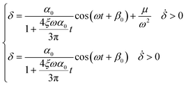 | (7) |
As depicted in Fig. 3(D), the driving force Fm exhibits an approximately linear relationship with the voltage amplitude. A maximum force of 5.1 mN appears when a 5 kV driving voltage is applied. Based on the theoretical model (eqn (7)), the vibration profiles of the micro-actuator can be obtained in Fig. 3(E), where all the amplitudes are above 1 mm and the maximum vibration velocity reaches the level of metres per second. The micro-actuator exhibits a powerful output performance. Moreover, we have conducted the vibration amplitude test under different driving frequencies. As the electric pulse frequency increases, the vibration amplitude increases linearly and reaches the maximum amplitude of 1.68 mm at the resonant frequency, as shown in Fig. 3(F). The micro-actuator operates well over a wide frequency range (from 50 Hz to 140 Hz) and exhibits powerful output characteristics at both low- and high-frequency drives. The vibration performance of the proposed millimetre-sized actuator is better than that of existing actuators that can achieve a greater amplitude only in the resonant frequency; however, the amplitude will significantly degrade in the lower driving frequencies.
Effect on actuator vibration characteristics of thermal accumulation under continuous electric stimulation
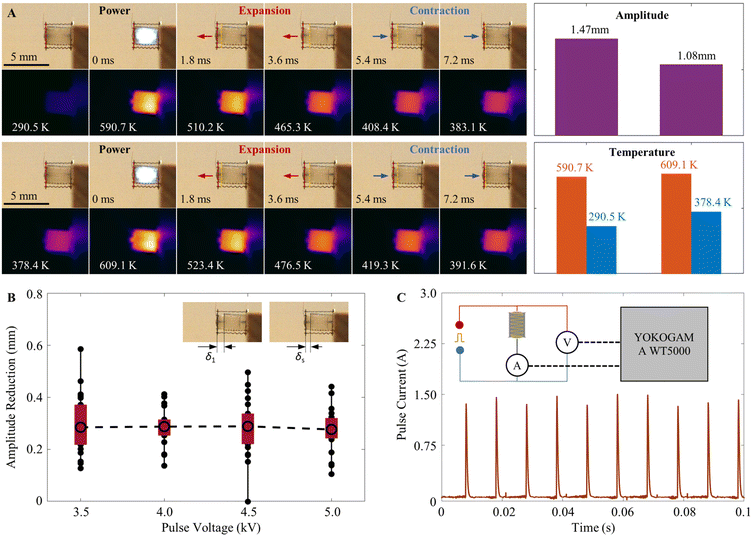
During the operation of the micro-actuator, the continuous electric pulse signal keeps the temperature inside the actuator chamber from cooling down completely, and the accumulated thermal energy will have an impact on the vibration amplitude of the actuator. As shown in Fig. 4(A), we have tested the vibration amplitude and temperature field variation of the actuator chamber under the initial electric signal drive and the continuous drive, respectively. It is demonstrated that the vibration amplitude decreases from 1.47 mm to 1.08 mm, a decrease of 26.5%, and the temperature of the actuator at the completion of one vibration cycle increases from 290.5 K to 378.4 K, an increase of 30.3%.In addition, we have tested the effect of the temperature accumulation of the micro-actuator under different electric pulses. As shown in Fig. 4(B), the amplitude difference between the initial amplitude δ1 and the stable amplitude δs driven by the continuous electric signal is about 0.3 mm at different electric pulses. This reduction is independent of the voltage amplitude. Although the reduction has some effect on the maximum amplitude of the actuator, it will have no further effect on the stable vibration, and the actuator can maintain a stable amplitude above the mm level.
Performance of the micro-actuator
In order to estimate the performance of the micro-actuator, we measured the power consumed during the operation using TEST&MEASUREMENT (YOKOGAMA, WT5000). The transient high currents in circuit systems were measured using Hall sensing, and the powering voltage remains consistent with the high-voltage pulse generator. This shows the instantaneous current values at a voltage of 4 kV and a pulse frequency of 100 Hz, as shown in Fig. 4(C), where the maximum current is up to 1.5 A with the stimulation time of μs level. The detailed tested transient current value is listed in the ESI.† In the calculation, we chose the transient current from a continuous ten cycles and multiplied these data by the powering voltage of 4 kV and the stimulation period of 1 μs. Then, the resultant value was averaged to obtain the electric power. The electric power, mechanical power, and energy efficiency of the micro-actuator for a single vibration are listed in Table 1.| Type | Value |
|---|---|
| All test results were measured at a voltage of 4 kV and a width of 1 μs. | |
| Actuator mass | 15.5 (mg) |
| Electric power | 2.25 (mW) |
| Mechanical power | 0.848 (mW) |
| Power density | 54.71 (W kg−1) |
| Energy efficiency | 37.7 (%) |
Although the instantaneous electric power reaches the kW level, the average power acting on the micro-actuator is only 2.25 mW. The mechanical output power is up to 0.848 mW, so the energy efficiency of the actuator can be estimated at 37.7%. Furthermore, the actuator has an output power density of 54.71 W kg−1 due to the quality of the milligram level. The proposed actuator is more powerful than electrostatic actuators,4 and the energy efficiency matches or even exceeds those of the PZT actuator, the DEA actuator and natural muscle.12,40
A millimetre-sized crawling robot driven by the micro-actuator
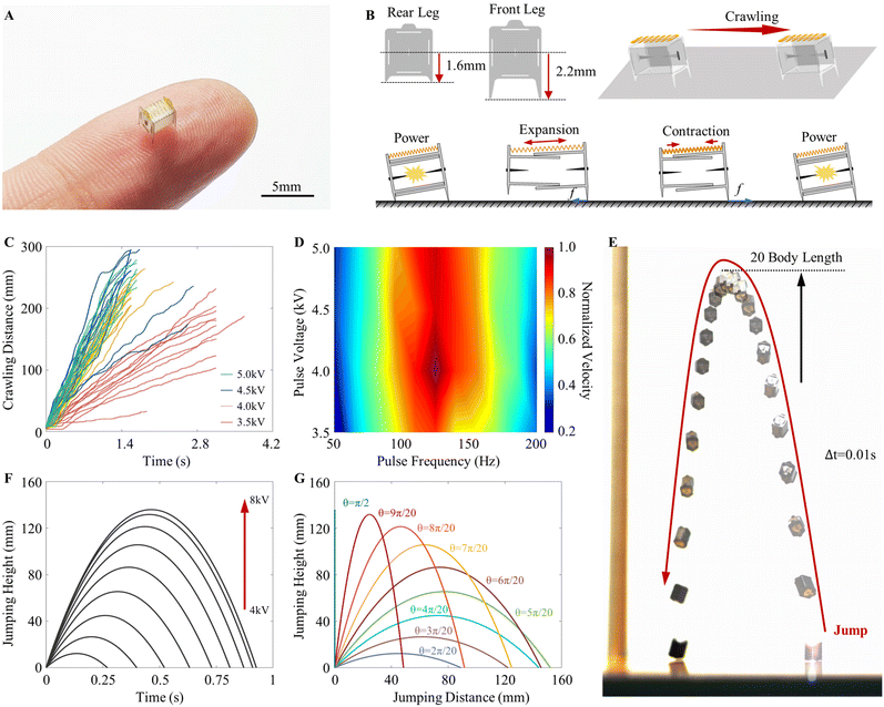
As illustrated in Fig. 5(A), we proposed a millimetre-sized crawling robot based on the micro-actuator. In the design of the robot's configuration, we have integrated the front and rear legs on the base of the actuator chamber, as shown in Fig. 5(B). The microrobot uses the frictional force f between the legs and the ground to achieve a crawling motion, whose crawl process is detailed in Movie S2.† In the test, the robot's crawling speed was measured under different electric signals. The crawling trajectory is shown in Fig. 5(C), where the robot crawls at a stable speed when the driving voltages are above 4 kV. At this moment, increasing the voltage does not significantly increase the crawling speed but will consume a large amount of electric power. In addition, we tested and verified that the electric pulse frequency has a greater influence on the crawling speed of the microrobot than on the voltage amplitude. Fig. 5(D) depicts the normalized crawling speed of the robot for different drive signals, with the maximum crawling speed occurring around the resonant frequency of the actuator. The fastest moving speed of the robot was measured to be up to 251.8 mm s−1 for an electric stimulation of 125 Hz. Micro-actuators exhibit considerable potential for millimetre-scale robotic driving applications.Powerful jumping ability of the micro-actuator
Except for the application of the micro-actuator to crawling robotics, the actuator also demonstrates great jumping capabilities. Fig. 5(E) exhibits that the micro-actuator can easily jump over 20 times its body length, and the detailed jumping process is shown in Movie S3.† In our research, we have investigated the impact factor of the actuator jumping height, such as driving voltages and jumping angles. In Fig. 5(F), as the voltage increases, the micro-actuator jumping height increases linearly, further confirming the linear relationship between voltages and the driving force Fm (Fig. 3(D)).In our previous study,5 the actuator could reach a maximum jumping height of 295 mm (87 times its body height), indicating that it can easily jump over obstacles ten times its size. In addition, the jumping height and jumping distance of the micro-actuator can be controlled by changing the jumping angle, as shown in Fig. 5(G). Whether it is active directional movement or passive casual movement in nature, the powerful output of the micro-actuator is the fundamental support for the fast movements of the microrobot. The jumping trajectories of the micro-actuator shown in Fig. 5(F) and (G) could be applied to achieve controlled motion in the robot's movement when exploring in a confined environment.
Comparison of the micro-actuator and related micro-robot with existing research
In nature, including mammals and arthropods, the relative crawling speed exhibits a strong negative scaling law with respect to body mass, indicating that the relative speed increases as the mass decreases. However, this scaling law does not seem to be accurate for robots and actuators, where lighter masses can also achieve fast relative crawling speeds. As shown in Fig. 6(A), the prototype of the microrobot proposed in this article can achieve the fastest measured crawling speed of up to 251.8 mm s−1 (74 body lengths per second). With its excellent crawling speed, the robot has approached or even surpassed the locomotion capabilities of many arthropods in nature. The micro-robot is currently the fastest-moving robot on milligram and millimetre scales, demonstrating the powerful performance of the novel actuator. All of the crawling speed data shown in Fig. 6(A) are from ref. 41.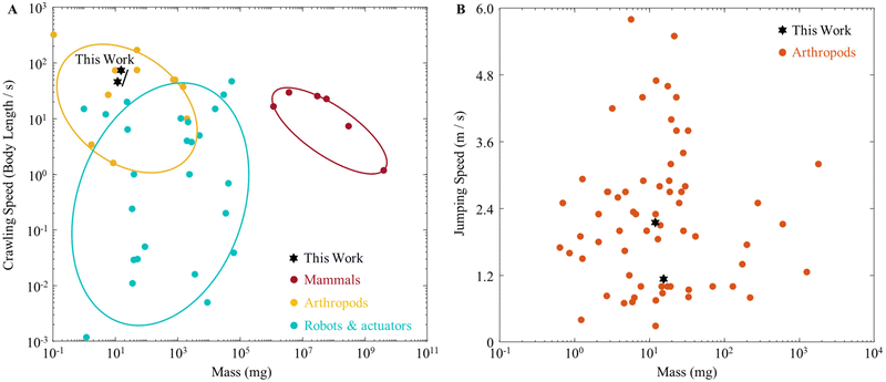 | ||
| Fig. 6 The comparison of crawling speed and jumping speed versus body mass. (A) Relative crawling speeds of some mammals, arthropods, soft robots, and actuators versus body mass. (B) A comparison of jumping speeds between the micro-actuator and arthropods in nature. The data on arthropods are from ref. 42. | ||
Mechanical performance, whether in animals or robots, is limited by the universal, physical trade-off between force and speed. However, in challenging environments and over a wide range of size scales, many biological systems use force-amplifying mechanisms to achieve unprecedented speeds. There are few actuators that can perform jumping movements on their own,33 and current research often relies on the additional use of elastic mechanisms as energy storage mechanisms to achieve jumping.1,24,31,42 Above a certain size (centimetre), the added elastic elements do improve the jumping ability; however, at smaller sizes (millimetre), the kinematic performance will drop significantly. The research in this paper overcomes this difficulty by relying solely on the propulsion of the actuator to achieve the jump. As shown in Fig. 6(B), the maximum jumping speed measured by the actuator reached 2.15 m s−1 and a steady jumping speed could be maintained at 1.133 m s−1. The excellent jumping ability of the micro-actuator exceeds the locomotion ability of many arthropods.
The work performance of our prototype micro-actuator is high as the simple structure has no redundant energy-consuming components. Some soft robots powered by magnetic fields, humidity, heat or light sources can have fast locomotion speeds, but their motions are severely limited by slow responses and a bulky structure to generate external power. The light mass and millimetre size of the micro-actuator can exceed the biologically demonstrated jumping ability without external amplification, making the actuator promising for use in the field of millimetre robot drives.
Future application and discussion
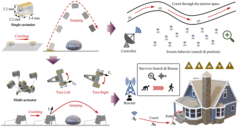
In the tests, the instantaneous voltage amplitude reaches the kV level and the current reaches the A level. Although the duration is only at the μs level, the robot's power consumption is large enough, which proposes a significant challenge to achieve untethered motion with the onboard circuit. Milligram and millimetre scale chip-based boost circuits are difficult to implement in a short time. Inspired by the existing literature,35,43 we will try to integrate the micro-actuator with a micro drive circuit to achieve wireless energy transfer by utilizing the laser or radiofrequency power. As shown in Fig. 7, the millimetre-sized and milligram-scale robots could cross through the confined space and also could jump over the obstacle using their powerful jumping abilities. In addition, due to the low cost of the robots, we can use a large number of robots to generate swarm behaviour for environmental search and detection. Moreover, we will focus on the multi-drive microrobot and achieve robot motion trajectory control using the operating duty cycle of different actuators. The multi-motor modes allow the robot to have both crawling and jumping locomotion, as shown in Fig. 7, and it can be used to enter a house in a dangerous scenario to guide the survivor out of the situation.Conclusions
In conclusion, we have proposed a novel electric micro-actuator based on plasmonic thermal energy. The operating mechanism is similar to that of a traditional piston engine. Once the plasmonic thermal energy is released, the chamber will expand to perform work and then contract under the restraint of elastic elements. The prepared micro-actuator responds to the kV-level pulse voltages. It can vibrate well from lower to higher frequencies and can also have significant amplitude during vibrations. In addition, we have designed the legs to be integrated with the micro-actuator to obtain a millimetre-sized crawling robot. The biomimetic crawling locomotion of the micro-actuator can achieve the fastest crawling speed of 251.8 mm s−1 (74 body lengths per second), and it can also easily jump over ten times its body length. Although our proposed micro-actuator loses some application scenarios compared to some soft actuators, it has the advantages of powerful power output, high energy conversion efficiency, milligram mass and millimetre size. We believe that this design of the novel micro-actuator, driven by the stimulus response of electric energy, will inspire the design and application of millimetre-sized robots in future detection and reconnaissance tasks.Author contributions
R. Yun proposed the idea, developed and conducted the experiments, and prepared the original manuscript. J. Che and Z. Liu helped with the experimental data collection. X. Yan and M. Qi reviewed and edited the original manuscript, and supervised the project. All the authors read, verified, and approved the final manuscript.Conflicts of interest
There are no conflicts to declare.Acknowledgements
This research was supported by the National Natural Science Foundation of China/Research Grant (52272384).References
- D. W. Haldane, M. M. Plecnik, J. K. Yim and R. S. Fearing, Sci. Robot., 2016, 1, eaag2048 CrossRef PubMed.
- Y. Ruan, A. S. Konstantinov, G. Shi, Y. Tao, Y. Li, A. J. Johnson, X. Luo, X. Zhang, M. Zhang, J. Wu, W. Li, S. Ge and X. Yang, Zookeys, 2020, 915, 87–105 CrossRef PubMed.
- Y. Pan, L. H. Lee, Z. Yang, S. U. Hassan and H. C. Shum, Nanoscale, 2021, 13, 18967–18976 RSC.
- R. Yun, L. Zhang, Y. Zhu, H. Zhang, W. Zhan, Z. Liu, X. Yan and M. Qi, Adv. Intell. Syst., 2023, 2200393 CrossRef.
- R. Yun, Z. Liu, J. Leng, J. Huang, Y. Cui, X. Yan and M. Qi, IEEE Robot. Autom. Lett., 2023, 8, 2868–2873 Search PubMed.
- E. Acome, S. K. Mitchell, T. G. Morrissey, M. B. Emmett, C. Benjamin, M. King, M. Radakovitz and C. Keplinger, Science, 2018, 359, 61–65 CrossRef CAS PubMed.
- P. Ohta, L. Valle, J. King, K. Low and Y. L. Park, Soft Robot., 2018, 5, 204–215 CrossRef PubMed.
- N. R. Sinatra, C. B. Teeple, D. M. Vogt, K. K. Parker, D. F. Gruber and R. J. Wood, Sci. Robot., 2019, 4, eaax5425 CrossRef PubMed.
- Y. Tang, Y. Chi, J. Sun, T.-H. Huang, O. H. Maghsoudi, A. Spence, J. Zhao, H. Su and J. Yin, Sci. Adv., 2020, 6, eaaz6912 CrossRef PubMed.
- D. Drotman, S. Jadhav, D. Sharp, C. Chan and M. T. Tolley, Sci. Robot., 2021, 6, eaay2627 CrossRef PubMed.
- T. Park, K. Kim, S. R. Oh and Y. Cha, Soft Robot., 2020, 7(1), 68–75 CrossRef PubMed.
- Y. Guo, L. Liu, Y. Liu and J. Leng, Adv. Intell. Syst., 2021, 3, 2000282 CrossRef.
- H. Meng and G. Li, J. Mater. Chem. A, 2013, 1, 7838–7865 RSC.
- J. Shang, X. Le, J. Zhang, T. Chen and P. Theato, Polym. Chem., 2019, 10, 1036–1055 RSC.
- P. Xie and R. Zhang, J. Mater. Chem., 2005, 15, 2529–2550 RSC.
- X. Ji, X. Liu, V. Cacucciolo, M. Imboden and H. Shea, Sci. Robot., 2019, 4, eaaz6451 CrossRef PubMed.
- D. L. Thomsen, P. Keller, J. Naciri, R. Pink, H. Jeon, D. Shenoy and B. R. Ratna, Macromolecules, 2001, 34, 5868–5875 CrossRef CAS.
- S.-J. Jeon, A. W. Hauser and R. C. Hayward, Acc. Chem. Res., 2017, 50, 161–169 CrossRef CAS PubMed.
- L. K. Rivera-Tarazona, V. D. Bhat, H. Kim, Z. T. Campbell and T. H. Ware, Sci. Adv., 2020, 6, eaax8582 CrossRef CAS PubMed.
- S. Kim, C. Laschi and B. Trimmer, Trends Biotechnol., 2013, 31, 287–294 CrossRef CAS PubMed.
- L. Hines, K. Petersen, G. Z. Lum and M. Sitti, Adv. Mater., 2016, 29, 1603483 CrossRef PubMed.
- L. Ricotti, B. Trimmer, A. W. Feinberg, R. Raman and K. K. Parker, Sci. Robot., 2017, 2, eaaq0495 CrossRef PubMed.
- G. Gu, Z. Jiang, R. Zhao, X. Zhao and X. Zhu, Sci. Robot., 2018, 3, eaat2874 CrossRef PubMed.
- Z. Zhakypov, K. Mori, K. Hosoda and J. Paik, Nature, 2019, 571, 381–386 CrossRef CAS PubMed.
- M. Karpelson, G.-Y. Wei and R. J. Wood, Sens. Actuators, A, 2012, 176, 78–89 CrossRef CAS.
- X. Liu, Z. Liu, Y. Zhu, J. Leng, M. Qi, J. Huang and X. Yan, J. Bionic Eng., 2021, 18, 662–673 CrossRef.
- C. Ahn, X. Liang and S. Cai, Adv. Mater. Technol., 2019, 4, 1900185 CrossRef CAS.
- K. L. Hoffman and R. J. Wood, Auton. Robots, 2011, 31, 103–114 CrossRef.
- B. Goldberg, N. Doshi, K. Jayaram and R. J. Wood, Bioinspiration Biomimetics, 2017, 12, 046005 CrossRef PubMed.
- W. Zhan, M. Qi, Z. Liu, J. Leng, H. Zhang, R. Yun and X. Yan, IEEE Robot. Autom. Lett., 2022, 7, 12483–12490 Search PubMed.
- E. W. Hawkes, C. Xiao, R.-A. Peloquin, C. Keeley, M. R. Begley, M. T. Pope and G. Niemeyer, Nature, 2022, 604, 657–661 CrossRef CAS PubMed.
- C. Zhang, W. Zou, L. Ma and Z. Wang, Robot. Auton. Syst., 2020, 124, 103362 CrossRef.
- W. Hu, G. Z. Lum, M. Mastrangeli and M. Sitti, Nature, 2018, 554, 81–85 CrossRef CAS PubMed.
- N. T. Jafferis, E. F. Helbling, M. Karpelson and R. J. Wood, Nature, 2019, 570, 491–495 CrossRef CAS PubMed.
- T. Ozaki, N. Ohta, T. Jimbo and K. Hamaguchi, Nat. Electron., 2021, 4, 845–852 CrossRef.
- M. Karásek, F. T. Muijres, C. De Wagter, B. D. W. Remes and G. C. H. E. de Croon, Science, 2018, 361, 1089–1094 CrossRef PubMed.
- H. Ishihara, F. Arai and T. Fukuda, IEEE/ASME Trans. Mechatron., 1996, 1, 68–79 CrossRef.
- W. S. N. Trimmer, Sens. Actuators, 1989, 19, 267–287 CrossRef.
- W. Kim, J. Byun, J. K. Kim, W. Y. Choi and K. J. Cho, Sci. Robot., 2019, 4, eaay3493 CrossRef PubMed.
- P. Brochu and Q. Pei, Macromol. Rapid Commun., 2010, 31, 10–36 CrossRef CAS PubMed.
- Y. Wu, J. K. Yim, J. Liang, Z. Shao, M. Qi, J. Zhong, Z. Luo, X. Yan, M. Zhang, X. Wang, R. S. Fearing, R. J. Full and L. Lin, Sci. Robot., 2019, 4, eaax1594 CrossRef PubMed.
- M. Ilton, M. S. Bhamla, X. Ma, S. M. Cox, L. L. Fitchett, Y. Kim, J.-s. Koh, D. Krishnamurthy, C.-Y. Kuo, F. Z. Temel, A. J. Crosby, M. Prakash, G. P. Sutton, R. J. Wood, E. Azizi, S. Bergbreiter and S. N. Patek, Science, 2018, 360, eaao1082 CrossRef PubMed.
- J. James, V. Iyer, Y. Chukewad, S. Gollakota and S. B. Fuller, Liftoff of a 190 mg Laser-Powered Aerial Vehicle: The Lightest Wireless Robot to Fly, IEEE International Conference on Robotics and Automation (ICRA), Brisbane, QLD, Australia, 2018, pp. 3587–3594 Search PubMed.
Footnote |
| † Electronic supplementary information (ESI) available. See DOI: https://doi.org/10.1039/d3nr01866k |
| This journal is © The Royal Society of Chemistry 2023 |


