 Open Access Article
Creative Commons Attribution 3.0 Unported Licence
A new two-dimensional luminescent Ag12 cluster-assembled material and its catalytic activity for reduction of hexacyanoferrate(III)†
Riki
Nakatani‡
 a,
Sourav
Biswas‡
 a,
Tsukasa
Irie
 a,
Jin
Sakai
a,
Daisuke
Hirayama
a,
Tokuhisa
Kawawaki
a,
Jin
Sakai
a,
Daisuke
Hirayama
a,
Tokuhisa
Kawawaki
 a,
Yoshiki
Niihori
 b,
Saikat
Das
 *b and
Yuichi
Negishi
 *ab
*ab
aDepartment of Applied Chemistry, Faculty of Science, Tokyo University of Science, Kagurazaka, Shinjuku-ku, Tokyo 162-8601, Japan. E-mail: negishi@rs.tus.ac.jp
bCarbon Value Research Center, Research Institute for Science & Technology, Tokyo University of Science, Tokyo 162-8601, Japan. E-mail: saikatdas@rs.tus.ac.jp
First published on 11th September 2023
Abstract
Silver cluster-assembled materials (SCAMs) have garnered significant interest as promising platforms for different functional explorations. Their atomically precise structures, intriguing chemical/physical properties, and remarkable luminescent capabilities make them highly appealing. However, the properties of these materials are primarily determined by their structural architecture, which is heavily influenced by the linker molecules used in their assembly. The choice of linker molecules plays a pivotal role in shaping the structural characteristics and ultimately determining the unique properties of SCAMs. To this end, the first SCAM with an intriguing (3,6)-connected kgd topology, [Ag12(StBu)6(CF3COO)6(TPBTC)6]n (termed TUS 3), TPBTC = benzene-1,3,5-tricarboxylic acid tris-pyridin-4-ylamide, has been synthesized by reticulating C6-symmetric Ag12 cluster cores with C3-symmetric tripodal pyridine linkers. Due to the structutural architecture of the linker molecule, TUS 3 posseses a luminescent porous framework structure where each two-dimensional (2D) layers are non-covalently linked with each other to form a three dimensional (3D) framework and ultimately offers uniaxial open channels. The compact mesoporous structural architecture not only gives the excellent surface area but also offers impressive stability of this material even in water medium. Taking advantage of these properties, TUS 3 shows brilliant catalytic activity in the reduction of hexacyanoferrate(III) using sodium borohydride in aqueous solutions.
Introduction
Since the advent of noble metal nanocluster (NC) synthesis, the pursuit of stability has become a paramount concern.1 Despite the remarkable correlation between their structure and properties, these NCs have posed significant challenges in maintaining their stability.2,3 However, researchers have made considerable strides in tackling this issue by employing a diverse range of methods aimed at achieving the highest level of stability possible.1,4,5 One particularly promising approach that has garnered attention is the utilization of organic linkers in the assembly of cluster nodes.1,6 This innovative technique has opened up new horizons for exploring the fascinating properties that emerge within the assembly network.7 By connecting individual NCs through organic linkers, scientists have been able to create intricate architectures that not only retain the discrete characteristics of the NCs but also exhibit enhanced and captivating properties arising from their collective behavior.The introduction of organic linkers has bestowed researchers with a wider scope to delve into the realm of NC assembly, enabling them to probe and manipulate the unique features and interactions that arise within these systems.6 This sophisticated approach has provided a platform for studying and optimizing properties such as optical, electronic, and catalytic behavior, among others. By carefully designing the organic linkers and controlling the assembly process, scientists can tailor the properties of the resulting NC assemblies to meet specific requirements and applications. Moreover, the exploration of these assembly networks offers valuable insights into the fundamental principles governing nanoscale self-assembly.8,9 By studying the interactions between the NCs and the organic linkers, researchers gain a deeper understanding of the underlying mechanisms that dictate the stability and behavior of these nanoscale systems.10
In a seminal work, Wang et al. introduced pyrazine linker to construct one-dimensional (1D) assemblies of fcc-Ag14 cluster nodes which were protected by 1,2-dithiolate-o-carborane.11 Furthermore, by substituting the linker molecule with trans-bipyridyl, they obtained a two-dimensional (2D) extended framework of the same cluster node. Lastly, by employing 4,4′-bipyridine as the linker molecule, they were able to obtain a three-dimensional (3D) framework. Therefore, the dimensional nature of the framework is contingent upon the geometric properties of the linker molecules. Subsequently, different linker molecules such as 3-amino-4,4′-bipyridine,12,13 4-pyridine carboxylic hydrazide,14 4,4′-azopyridine,15–17 [tris(4-pyridylphenyl)-amine],18 [5,10,15,20-tetra(4-pyridyl)porphyrin],19,20 (1,4-bis(pyrid-4-yl)benzenenamine,21 1,4-bis(pyridin-4-ylethynyl)benzene),22 1,2-bis(4-pyridyl)ethane,23 1,1,2,2-tetrakis(4-(pyridin-4-ylethynyl)phenyl)ethene,24 9,10-bis(2-(pyridin-4-yl)vinyl)anthracene25 were utilized to create various silver cluster-assembled materials (SCAMs) by assembling different Ag(I) cluster nodes. Notably, the utilization of Ag12 cluster nodes as a model system revealed an intriguing observation: the dimensionality of the resulting structures consistently correlated with the structural architecture of the linker molecule.13,19,26–28
The quest for stability is a crucial prerequisite when it comes to assembling cluster nodes, as it enhances their potential for practical applications.1 Nevertheless, in many cases, the primary focus has been on establishing synthetic routes for these materials and elucidating the correlation between their structure and properties.29,30 Although there are some exceptions where these materials have been used for suitable applications, their number is relatively limited.1 Therefore, given the significant progress in this field, it is imperative to synthesize new SCAMs that exhibit sustainable stability and offer exceptional applicability.
Based on the aforementioned observations, we present the utilization of a novel N-containing tridentate linker molecule, benzene-1,3,5-tricarboxylic acid tris-pyridin-4-ylamide (TPBTC), for the construction of a 2D assembly of Ag12 cluster nodes. This unique arrangement contributes to the structural integrity and opens up possibilities for diverse applications. While concerns regarding the solubility persist, its exceptional stability in aqueous environments greatly expands its potential for practical use. One striking aspect of this material is the abundance of catalytic active sites that contributes to its excellent catalytic activity in the reduction of Fe(CN)63− using NaBH4 in aqueous solutions. This noteworthy performance underscores its effectiveness as a catalyst for this specific reaction. Furthermore, its outstanding reusability further enhances its value, as it demonstrates consistent catalytic performance even after undergoing multiple cycles. Thus, the stability of this material, both in terms of its structural integrity and its catalytic performance, provides a new avenue for exploration in various fields. The stability of this material, serving as a fundamental attribute, paves the way for exciting advancements and opportunities in scientific research and technological innovation.
Results and discussion
TUS 3 was synthesized and crystallized by using a facile reaction method. The initial reaction involved combining [AgStBu]n and CF3COOAg in ethanol/acetonitrile (EtOH/MeCN) solution medium. On the other side, the linker was dissolved in an N-methyl-2-pyrrolidone (NMP) solution and placed at the bottom of a cent tube. Carefully, the initial reactant mixture was then added on top of the linker solution, resulting in the formation of two distinct layers (Fig. 1). The cent tube was subsequently placed in a dark environment to facilitate crystallization. After a period of 3 days, block-shaped crystals with an off-white color were produced at the junction of the inorganic and organic layers with a yield of ∼22% (based on Ag metal). Thus, the initial reaction between [AgStBu]n and CF3COOAg yields the Ag cluster nodes, which gradually connected with the linker molecules during the process of carefully placing them to separate the two liquid interfaces. The optical microscope and scanning electron microscope (SEM) images confirm the growth of the crystal three-dimensionally along with its block-shaped morphology (Fig. S1† and Fig. 1). Since we did not use any reducing agent in this reaction, so we expect that all the Ag atoms are positively charged. We confirmed this information through additional experiments, which we discussed in the later section.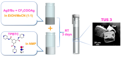 | ||
| Fig. 1 Schematic illustration of the preparation route to TUS 3 single crystals. The SEM image of the obtained crystals is depicted in the magnified view. | ||
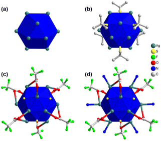
In order to obtain a more comprehensive understanding of the detailed structure of the crystal, single-crystal X-ray diffraction (SCXRD) was employed for characterization. The crystallographic analysis revealed that the single crystal has a trigonal crystal system and belongs to the R![[3 with combining macron]](https://www.rsc.org/images/entities/char_0033_0304.gif) (no. 148) space group (Table S1†). Through this analysis, it was determined that each cluster node within the crystal consists of twelve Ag(I) atoms, six thiolate ligands, six trifluoroacetate auxiliary ligands, and six linker molecules. An intriguing observation is that the twelve Ag(I) atoms are arranged in a hollow cuboctahedral geometry (Fig. 2a), with an average Ag–Ag distance of approximately 3.2961 Å. This average distance falls within the range of twice the van der Waals radius of Ag, suggesting that the geometric arrangement of Ag(I) atoms is governed by the argentophilic interaction.31 In terms of geometry, this arrangement corresponds to an Archimedean solid with eight triangular facets and six trapezoidal facets. To establish a connection between the Ag12 structural architecture and the Archimedean solid geometry, the structure can be divided into three distinct planes (Fig. S2†). Two equatorial triangular planes, each consisting of three Ag(I) atoms, are situated at the top and bottom of the structure in opposite directions, with an Ag–Ag distance of 3.0962 Å. The middle layer is composed of another six Ag(I) atoms, with a similar Ag–Ag distance of approximately 3.8249 Å. Although this distance is slightly greater than twice the van der Waals radius of Ag atoms, the interconnections between the planes maintain the structural integrity. By considering the connections among the three planes, a total of fourteen facets can be identified, resembling the hollow cuboctahedron-like geometry described earlier (Fig. S2†).
(no. 148) space group (Table S1†). Through this analysis, it was determined that each cluster node within the crystal consists of twelve Ag(I) atoms, six thiolate ligands, six trifluoroacetate auxiliary ligands, and six linker molecules. An intriguing observation is that the twelve Ag(I) atoms are arranged in a hollow cuboctahedral geometry (Fig. 2a), with an average Ag–Ag distance of approximately 3.2961 Å. This average distance falls within the range of twice the van der Waals radius of Ag, suggesting that the geometric arrangement of Ag(I) atoms is governed by the argentophilic interaction.31 In terms of geometry, this arrangement corresponds to an Archimedean solid with eight triangular facets and six trapezoidal facets. To establish a connection between the Ag12 structural architecture and the Archimedean solid geometry, the structure can be divided into three distinct planes (Fig. S2†). Two equatorial triangular planes, each consisting of three Ag(I) atoms, are situated at the top and bottom of the structure in opposite directions, with an Ag–Ag distance of 3.0962 Å. The middle layer is composed of another six Ag(I) atoms, with a similar Ag–Ag distance of approximately 3.8249 Å. Although this distance is slightly greater than twice the van der Waals radius of Ag atoms, the interconnections between the planes maintain the structural integrity. By considering the connections among the three planes, a total of fourteen facets can be identified, resembling the hollow cuboctahedron-like geometry described earlier (Fig. S2†).
Now let us consider the attachment of ligands and linker molecules to the Ag12 cluster node. As previously mentioned, each cluster node is associated with six thiolate ligands. It is noteworthy that these thiolate ligands are positioned at the trapezoidal facets, extending outward from the cluster node (Fig. 2b). Consequently, each thiolate ligand forms connections with four Ag(I) atoms located within each trapezoidal facet. The connection between the upper plane and the middle plane comprises three thiolate ligands. Each of these thiolate ligands is linked to two Ag(I) atoms from the upper plane and two Ag(I) atoms from the middle plane. Similarly, the connection between the bottom plane and the middle plane involves an additional three thiolate ligands. Each of these ligands is connected to two Ag(I) atoms from the lower plane and two Ag(I) atoms from the middle plane. Consequently, the average distances between the S and Ag atoms in the middle plane, S and the upper plane, and S and the lower plane are 2.5743 Å, 2.4653 Å, and 2.4653 Å, respectively. Interestingly, a similar number of auxiliary ligands (–CF3COO−) are also present on the Ag(I) cluster node, in addition to the main thiolate ligand, serving to safeguard the surface (Fig. 2c). These auxiliary ligands are attached to the six triangular facets on the outer part of the middle layer. Each –CF3COO− ligand is linked to three Ag(I) atoms through oxygen atoms, utilizing η1 bridging mode. However, the two O atoms establish distinct connections: one O atom links the auxiliary ligands to the middle plane of the cluster node, while the other O atom connects them to either the upper or lower plane. Regarding the connection with the middle layer, the Ag–O bond distance measures 2.6489 Å. However, in the case of the connection with the upper or lower layers, the distance measures 2.4891 Å. Consequently, all twelve facets on the outer surface of the cluster node are now capped by ligands, effectively protecting it. To further enhance the protective properties, linker molecules are exclusively attached at the edges of the middle plane (Fig. 2d). Therefore, six linker molecules form Ag–N bonds with the six Ag(I) atoms on the middle plane of the cluster node, exhibiting a bond distance of 2.2761 Å. It is intriguing to observe that despite the distinct structural architectures of linker molecules, the attachment of six linker molecules does not interfere with the formation and connectivity of Ag cluster nodes.
Fascinatingly, each linker molecule possesses three coordinating sites with three nitrogen atoms located at its ends, allowing it to connect with three adjacent cluster nodes (Fig. 3a). Due to the planar structure of the linker molecule, it facilitates the connection of cluster nodes within the same plane. As a result, each cluster node is linked to six other cluster nodes on the same plane through the linker molecules (Fig. 3a). This arrangement creates a well-defined network within the system, where the linker molecules serve as bridges, effectively connecting multiple cluster nodes and contributing to the overall stability and structure of the system. Hence, TUS 3 could be identified as binodal (3,6)-connected 2D network adopting the kgd (kagome dual) layered topology formed from the combination of three-connected C3-symmetric TPBTC linker with six-connected C6-symmetric Ag12 cluster node (Fig. S3†).32 Moreover, facilitated by the non-covalent interactions between the linker molecules, the layers are stacked in a 3D architecture, giving rise to 1D open channels conducive to mass transport (Fig. 3b). The separation distance between these layers measures 17.2 Å (Fig. S4†). Consequently, the Ag12 cluster nodes contribute to the formation of a 3D architectural framework. Notably, the structural characteristics of the linker molecule result in the presence of pore spaces within its arrangement. The SCXRD experiment revealed the presence of solitary solvent molecules within these empty regions, drawing attention to the fascinating structural design of the system (Fig. S5†).
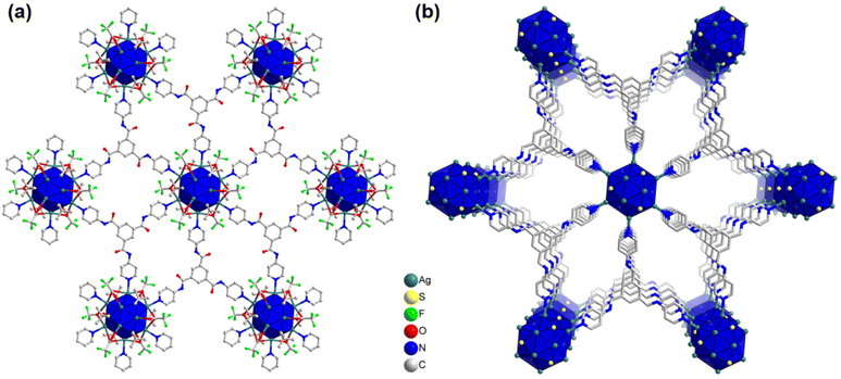 | ||
| Fig. 3 (a) Planar 2D architecture of TUS 3 where Ag12 cluster nodes are linked with the linker molecules, (b) 3D architecture of TUS 3. For clarity, linker part occasionally and H atoms are omitted. | ||
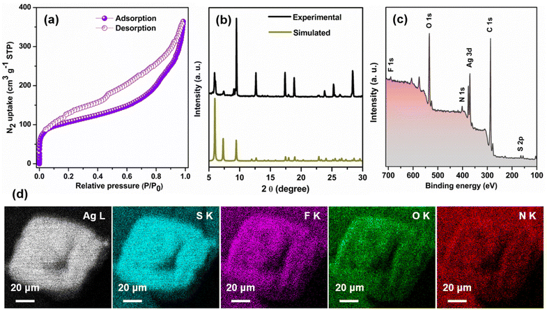
Nevertheless, subjecting the system to degassing at a temperature 50 °C for a duration of 8 hours prior to N2 sorption measurements at 77 K effectively eliminates the solvent molecules from the pores. As evident from Fig. 4a, TUS 3 displayed type-IV isotherms, indicative of its mesoporous character.33 Utilization of the Brunauer–Emmett–Teller (BET) theory furnished a specific surface area of 394 m2 g−1 (Fig. S6†). The non-local density functional theory (NLDFT) calculations demonstrated a distribution of pore size centered at 2.58 and 7.03 nm (Fig. S7†). While the experimentally derived pore size of 7.03 nm is in conformity with the calculated pore size of ∼8 nm, the pore size centered at 2.58 nm is owing to the partial occupancy of TUS 3 pores by NMP molecules. To thoroughly assess the purity of the crystals, an extensive analysis was conducted. Firstly, a comparison between the experimental powder X-ray diffraction (PXRD) and simulated patterns was performed. The excellent matching observed, particularly in the lower angle peaks, provides strong evidence supporting the stability and high purity of the crystal in its powdered state (Fig. 4b). However, the presence of another crystalline phase in the powdered TUS 3 could be linked to two minor peaks, approximately at 6.08° and 9.08°. To further investigate and confirm the elemental composition of the TUS 3 crystals, X-ray photoelectron spectroscopy (XPS) measurements were carried out on the dried and degassed samples. The survey spectrum obtained from the XPS analysis revealed the presence of several elements, including Ag, S, F, O, N, and C (Fig. 4c). This comprehensive elemental confirmation provides valuable insights into the composition of the crystals. Moreover, the results obtained from XPS were effectively corroborated by scanning electron microscopy with energy-dispersive X-ray spectroscopy (SEM-EDS) analysis. By utilizing SEM-EDS, the distribution of these elements throughout the crystal structure was accurately mapped (Fig. 4d). This detailed mapping of the elemental composition further supports the earlier findings and enhances our understanding of the internal structure of this crystal. In addition to this, the high-resolution binding energy spectrum of each element offers valuable insights into the oxidation state of individual elements (Fig. S8†). The presence of corresponding peaks in the spectrum serves as confirmation of the existence of Ag(I) atoms, along with the −1-oxidation state of S. The thermogravimetric analysis (TGA) confirms its thermal stability up to 100 °C (Fig. S9†).
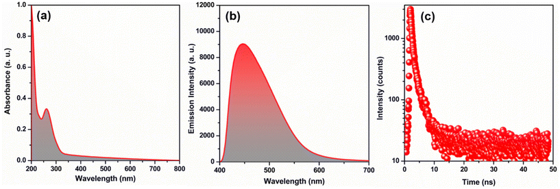
Despite the satisfactory stability of TUS 3, its solubility is limited, which can impact its practical usability. The solubility of a substance, especially in water, plays a crucial role in determining its applicability. Therefore, in order to enhance its practical utility, it becomes essential to verify the structural integrity of TUS 3 in water medium. This was achieved by comparing the PXRD patterns obtained before and after immersing the TUS 3 crystals in water. The presence of well-matched PXRD patterns indicates the retention of crystalline structure of TUS 3 even after exposure to water (Fig. S10a†). This confirmation provides assurance regarding its suitability for use in water-based applications, thereby enhancing its overall applicability. Nevertheless, we have also ascertained the stability of TUS 3 in dichloromethane and ethanol solvents; yet it exhibits comparatively lower stability in NaOH and HCl solutions (Fig. S10b†). To find the suitable applicability we have to understand its property which is correlated with its structural architecture. As the material is quite stable in water medium, so we conducted a comprehensive study by dispersing it in water. During UV-Vis absorbance study, we observed a prominent peak in the 261 nm region, which remained consistent even when we replaced the water solvent with NMP, our reactant solvent (Fig. 5a and Fig. S11†). To further validate the absorption property of the material, we compared our findings with the UV-Vis absorbance of the TPBTC linker molecule alone (Fig. S11†). A distinct observation emerged from this comparison: a noteworthy blue shift of 25 nm. This shift clearly indicates that the observed peak originates exclusively from TUS 3 and not from the linker molecule alone. Additionally, we conducted an analysis of the emission properties of TUS 3 when dispersed in a water medium. Upon excitation at 330 nm, we observed a distinct emission peak at 445 nm, with an absolute luminescence quantum yield of 0.55 (Fig. 5b). Remarkably, this emission property exhibited consistency with its solid-state emission behavior, where the emission maximum occurs in the 436 nm region (Fig. S12†). This subtle variance in the emission maximum can be ascribed to the interaction occurring between the cluster and the solvent, elucidating their influence on the emission properties. To gain further insight into the emission characteristics of TUS 3 in a water medium, we employed time-correlated single-photon counting (TCSPC) techniques. We conducted measurements to determine the emission lifetime of TUS 3, revealing a value of 1.34 ns as illustrated in Fig. 5c. The emission lifetime was accurately fitted with bi-exponential factors, providing a comprehensive understanding of the decay kinetics (Table S2†). These two components are likely attributed to electronic transitions occurring between the metal and the ligand or linker molecules. These detailed observations and measurements provide a comprehensive understanding of the emission properties of TUS 3 in a water medium.
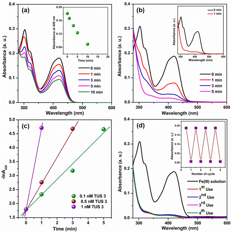
Given the extensive optical properties of TUS 3, we decided to explore its potential applications in a water medium. Upon reviewing existing literature, we found that the fluorescence properties of SCAMs have already been employed in sensing various substances and photo degradation of pollutants. Building upon this knowledge, we aimed to investigate the effectiveness of this type of unique structural architecture as a catalyst for the reduction of Fe(CN)63− using NaBH4 in a water medium. Previous studies have utilized various nanoparticles for this particular catalytic process.34–36 However, those nanoparticles often suffer from aggregation issues during the catalytic reaction, which can impede their performance.34 In contrast, by utilizing an extended framework such as TUS 3, we anticipate overcoming these aggregation-related drawbacks. The extended framework of TUS 3 offers promising advantages, including enhanced stability and minimized aggregation tendencies during catalytic reactions. To monitor the catalytic reaction process, we employed UV-Vis absorbance measurements. The reduction of Fe(CN)63− by BH4− ions in a water medium proceeds at a relatively slow rate, which is evident from the depletion of the Fe(CN)63− peak at 420 nm (Fig. 6a).35 We observed a decline in absorbance at 420 nm with time (Fig. 6a, inset). However, an intriguing discovery occurred when TUS 3 was introduced at a specific concentration into the reaction mixture, resulting in a significantly accelerated reaction (Fig. 6b and Fig. S13†). We obtained a first-order rate constant value at 25 °C by plotting −ln![[thin space (1/6-em)]](https://www.rsc.org/images/entities/char_2009.gif) A420 against time.35 In addition, the obtained rate constant was found to be dependent on the concentration of TUS 3. By gradually increasing the concentration of TUS 3 from 0.1 to 1 nM, we observed a corresponding increase in the rate constant, from 55.9 × 10⁻² min−1 to 291.9 × 10⁻² min−1 (Fig. 6c). Remarkably, the calculated half-life (t1/2) decreased significantly, reaching 14 s with the incorporation of 1 nM TUS 3, compared to an initial t1/2 of 74 s with 0.1 nM TUS 3. The effectiveness of this catalyst becomes apparent when we compared our results with those of its nanoparticle counterpart (Table S3†). Upon examining the mechanistic pathway of this reaction, it becomes evident that following the charging of the TUS 3 framework surface through the addition of a reducing agent (NaBH4), the stored electrons can be liberated upon the introduction of an electron acceptor into the system. Thus, it demonstrate that the addition of TUS 3 can lead to a potential breakthrough in the reduction of Fe(CN)63− using NaBH4 in water medium. This novel application holds tremendous promise for addressing existing challenges and advancing catalytic processes, particularly in the realm of environmental remediation. Furthermore, we evaluated the reusability of TUS 3 in the catalytic reaction and found that it maintained consistent performance even after the 4th cycle. The Fourier-transform infrared (FT-IR) spectrum analysis of TUS 3 before and after catalysis across multiple cycles, displayed a remarkable degree of conformity, affirming the chemical integrity of TUS 3 (Fig. S14a†). Furthermore, the congruent PXRD patterns of TUS 3 before and after catalysis underscored the structural stability maintained during the catalytic activity (Fig. S14b†). As observable from high-resolution transmission electron microscopy (HRTEM) imaging, the crystalline structure of TUS 3 was well-maintained after catalysis (Fig. S15†). Additionally, EDS analysis confirmed that no adsorption of foreign ions occurred within the framework during catalytic process, further emphasizing the stability of the TUS 3 framework (Fig. S16†). This comprehensive analysis demonstrates the immense potential of TUS 3 in catalytic reactions, especially in the reduction of Fe(CN)63− using NaBH4 in aqueous solutions. Moreover, the structural integrity, reusability, and stability of TUS 3 highlight its suitability for a wide range of applications in environmental remediation and related fields.
A420 against time.35 In addition, the obtained rate constant was found to be dependent on the concentration of TUS 3. By gradually increasing the concentration of TUS 3 from 0.1 to 1 nM, we observed a corresponding increase in the rate constant, from 55.9 × 10⁻² min−1 to 291.9 × 10⁻² min−1 (Fig. 6c). Remarkably, the calculated half-life (t1/2) decreased significantly, reaching 14 s with the incorporation of 1 nM TUS 3, compared to an initial t1/2 of 74 s with 0.1 nM TUS 3. The effectiveness of this catalyst becomes apparent when we compared our results with those of its nanoparticle counterpart (Table S3†). Upon examining the mechanistic pathway of this reaction, it becomes evident that following the charging of the TUS 3 framework surface through the addition of a reducing agent (NaBH4), the stored electrons can be liberated upon the introduction of an electron acceptor into the system. Thus, it demonstrate that the addition of TUS 3 can lead to a potential breakthrough in the reduction of Fe(CN)63− using NaBH4 in water medium. This novel application holds tremendous promise for addressing existing challenges and advancing catalytic processes, particularly in the realm of environmental remediation. Furthermore, we evaluated the reusability of TUS 3 in the catalytic reaction and found that it maintained consistent performance even after the 4th cycle. The Fourier-transform infrared (FT-IR) spectrum analysis of TUS 3 before and after catalysis across multiple cycles, displayed a remarkable degree of conformity, affirming the chemical integrity of TUS 3 (Fig. S14a†). Furthermore, the congruent PXRD patterns of TUS 3 before and after catalysis underscored the structural stability maintained during the catalytic activity (Fig. S14b†). As observable from high-resolution transmission electron microscopy (HRTEM) imaging, the crystalline structure of TUS 3 was well-maintained after catalysis (Fig. S15†). Additionally, EDS analysis confirmed that no adsorption of foreign ions occurred within the framework during catalytic process, further emphasizing the stability of the TUS 3 framework (Fig. S16†). This comprehensive analysis demonstrates the immense potential of TUS 3 in catalytic reactions, especially in the reduction of Fe(CN)63− using NaBH4 in aqueous solutions. Moreover, the structural integrity, reusability, and stability of TUS 3 highlight its suitability for a wide range of applications in environmental remediation and related fields.
Conclusions
We presented the facile one-pot construction of the first (3,6)-connected SCAM with a 2D kgd net. Intriguingly, the stitching of Ag12 cluster nodes with tripodal pyridine linkers resulted in a 2D layered framework wherein the layers are stacked in a 3D architecture, generating open 1D mesoporous channels that serve as pathways for mass transport. The obtained structural architecture not only demonstrates remarkable stability and distinct fluorescence characteristics, but also exhibits outstanding catalytic activity in the reduction of Fe(CN)63− using NaBH4 in aqueous solutions. The transition from a zeroth-order to a first-order rate constant indicates the ability of TUS 3 to transfer negative charge to the reactant molecule, with the help of its mesoporous framework structure. Thus, our research contributes to a deeper understanding of how rational design strategies, optimized synthesis conditions, and systematic tuning of pore environments in SCAMs can effectively control targeted catalytic pathways, leading to the development of high-performance catalysts.Experimental
Synthesis of TUS 3
Initially, AgStBu (24 mg, 0.12 mmol) and CF3COOAg (24 mg, 0.11 mmol) were mixed together in presence of a mixed solvent of ethanol and acetonitrile (1![[thin space (1/6-em)]](https://www.rsc.org/images/entities/char_2009.gif) :
:![[thin space (1/6-em)]](https://www.rsc.org/images/entities/char_2009.gif) 1, 5 mL) under stirring. On the other hand, TPBTC (26.8 mg, 0.06 mmol) linker was dissolved in a separate glass vial containing 5 mL of NMP. Later on, 1 mL from each vial was transferred to a cent tube and kept for crystallization at room temperature in a dark environment. After a period of 3 days, off-white block-shaped crystals (2.7 mg) were obtained at the interface between the inorganic and organic phases.
1, 5 mL) under stirring. On the other hand, TPBTC (26.8 mg, 0.06 mmol) linker was dissolved in a separate glass vial containing 5 mL of NMP. Later on, 1 mL from each vial was transferred to a cent tube and kept for crystallization at room temperature in a dark environment. After a period of 3 days, off-white block-shaped crystals (2.7 mg) were obtained at the interface between the inorganic and organic phases.
Author contributions
R. N.: synthesis, characterization, and application. S. B.: characterization, application, and writing manuscript. T. I.: characterization. J. S.: synthesis and SCXRD measurement. D. H.: XPS measurement and analysis. T. K.: XPS measurement and analysis. Y. Niihori: SCXRD measurement. S. D.: conceptualization, supervision, and writing manuscript. Y. Negishi: conceptualization, supervision, and writing manuscript.Conflicts of interest
There are no conflicts to declare.Acknowledgements
The authors thank Sayaka Furumoto for assisting in the synthesis and SCXRD measurements. Funding provided by the JSPS KAKENHI (grant no. 20H02698, 20H02552), Ogasawara Foundation for the Promotion of Science and Engineering, Yazaki Memorial Foundation for Science and Technology, and “Aquatic Functional Materials” (grant no. 22H04562).References
- S. Biswas, S. Das and Y. Negishi, Coord. Chem. Rev., 2023, 492, 215255 CrossRef CAS.
- R. Jin, C. Zeng, M. Zhou and Y. Chen, Chem. Rev., 2016, 116, 10346–10413 CrossRef CAS PubMed.
- I. Chakraborty and T. Pradeep, Chem. Rev., 2017, 117, 8208–8271 CrossRef CAS PubMed.
- Y. Jin, C. Zhang, X.-Y. Dong, S.-Q. Zang and T. C. W. Mak, Chem. Soc. Rev., 2021, 50, 2297–2319 RSC.
- P. Chakraborty, A. Nag, A. Chakraborty and T. Pradeep, Acc. Chem. Res., 2019, 52, 2–11 CrossRef CAS PubMed.
- A. Ebina, S. Hossain, H. Horihata, S. Ozaki, S. Kato, T. Kawawaki and Y. Negishi, Nanomaterials, 2020, 10, 1105 CrossRef CAS PubMed.
- S. Biswas, P. Sun, X. Xin, S. Mandal and D. Sun, in Atomically Precise Nanochemistry, 2023, pp. 453–478, DOI:10.1002/9781119788676.ch15.
- S. A. Claridge, A. W. Castleman Jr., S. N. Khanna, C. B. Murray, A. Sen and P. S. Weiss, ACS Nano, 2009, 3, 244–255 CrossRef CAS PubMed.
- A. W. Castleman Jr. and S. N. Khanna, J. Phys. Chem. C, 2009, 113, 2664–2675 CrossRef.
- X. Kang and M. Zhu, Coord. Chem. Rev., 2019, 394, 1–38 CrossRef CAS.
- Z.-Y. Wang, M.-Q. Wang, Y.-L. Li, P. Luo, T.-T. Jia, R.-W. Huang, S.-Q. Zang and T. C. W. Mak, J. Am. Chem. Soc., 2018, 140, 1069–1076 CrossRef CAS PubMed.
- X.-H. Ma, J.-Y. Wang, J.-J. Guo, Z.-Y. Wang and S.-Q. Zang, Chin. J. Chem., 2019, 37, 1120–1124 CrossRef CAS.
- X.-Y. Dong, Y. Si, J.-S. Yang, C. Zhang, Z. Han, P. Luo, Z.-Y. Wang, S.-Q. Zang and T. C. W. Mak, Nat. Commun., 2020, 11, 1–9 CrossRef PubMed.
- S.-H. Lu, Y. Li, S.-X. Yang, R.-D. Zhao, Z.-X. Lu, X.-L. Liu, Y. Qin, L.-Y. Zheng and Q.-E. Cao, Inorg. Chem., 2019, 58, 11793–11800 CrossRef CAS PubMed.
- A. K. Das, S. Biswas, A. Thomas, S. Paul, A. S. Nair, B. Pathak, M. S. Singh and S. Mandal, Mater. Chem. Front., 2021, 5, 8380–8386 RSC.
- A. K. Das, S. Biswas, S. S. Manna, B. Pathak and S. Mandal, Inorg. Chem., 2021, 60, 18234–18241 CrossRef CAS PubMed.
- S. Biswas, A. K. Das, A. Nath, S. Paul, M. S. Singh and S. Mandal, Nanoscale, 2021, 13, 17325–17330 RSC.
- X.-S. Du, B.-J. Yan, J.-Y. Wang, X.-J. Xi, Z.-Y. Wang and S.-Q. Zang, Chem. Commun., 2018, 54, 5361–5364 RSC.
- M. Cao, R. Pang, Q.-Y. Wang, Z. Han, Z.-Y. Wang, X.-Y. Dong, S.-F. Li, S.-Q. Zang and T. C. W. Mak, J. Am. Chem. Soc., 2019, 141, 14505–14509 CrossRef CAS PubMed.
- M. Zhao, S. Huang, Q. Fu, W. Li, R. Guo, Q. Yao, F. Wang, P. Cui, C.-H. Tung and D. Sun, Angew. Chem., Int. Ed., 2020, 59, 20031–20036 CrossRef CAS.
- Y.-M. Wang, J.-W. Zhang, Q.-Y. Wang, H.-Y. Li, X.-Y. Dong, S. Wang and S.-Q. Zang, Chem. Commun., 2019, 55, 14677–14680 RSC.
- S. Das, T. Sekine, H. Mabuchi, S. Hossain, S. Das, S. Aoki, S. Takahashi and Y. Negishi, Chem. Commun., 2023, 59, 4000–4003 RSC.
- J.-Y. Wang, R.-W. Huang, Z. Wei, X.-J. Xi, X.-Y. Dong and S.-Q. Zang, Chem. – Eur. J., 2019, 25, 3376–3381 CrossRef CAS PubMed.
- J. Sakai, S. Biswas, T. Irie, H. Mabuchi, T. Sekine, Y. Niihori, S. Das and Y. Negishi, Nanoscale, 2023, 15, 12227–12234 RSC.
- T. Sekine, J. Sakai, Y. Horita, H. Mabuchi, T. Irie, S. Hossain, T. Kawawaki, S. Das, S. Takahashi, S. Das and Y. Negishi, Chem. – Eur. J., 2023, 29, e202300706 CrossRef CAS PubMed.
- R.-W. Huang, Y.-S. Wei, X.-Y. Dong, X.-H. Wu, C.-X. Du, S.-Q. Zang and T. C. W. Mak, Nat. Chem., 2017, 9, 689–697 CrossRef CAS PubMed.
- W. A. Dar, A. Jana, K. S. Sugi, G. Paramasivam, M. Bodiuzzaman, E. Khatun, A. Som, A. Mahendranath, A. Chakraborty and T. Pradeep, Chem. Mater., 2022, 34, 4703–4711 CrossRef CAS.
- R.-W. Huang, X.-Y. Dong, B.-J. Yan, X.-S. Du, D.-H. Wei, S.-Q. Zang and T. C. W. Mak, Angew. Chem., Int. Ed., 2018, 57, 8560–8566 CrossRef CAS PubMed.
- M. J. Alhilaly, R.-W. Huang, R. Naphade, B. Alamer, M. N. Hedhili, A.-H. Emwas, P. Maity, J. Yin, A. Shkurenko, O. F. Mohammed, M. Eddaoudi and O. M. Bakr, J. Am. Chem. Soc., 2019, 141, 9585–9592 CrossRef CAS PubMed.
- Z. Wang, H.-F. Su, L.-P. Zhang, J.-M. Dou, C.-H. Tung, D. Sun and L. Zheng, ACS Nano, 2022, 16, 4500–4507 CrossRef CAS PubMed.
- H. Schmidbaur and A. Schier, Angew. Chem., Int. Ed., 2015, 54, 746–784 CrossRef CAS PubMed.
- H. Bhambri, S. Khullar, Sakshi and S. K. Mandal, Mater. Adv., 2022, 3, 19–124 RSC.
- M. Thommes, K. Kaneko, A. V. Neimark, J. P. Olivier, F. Rodriguez-Reinoso, J. Rouquerol and K. S. W. Sing, Pure Appl. Chem., 2015, 87, 1051–1069 CrossRef CAS.
- P. Hervés, M. Pérez-Lorenzo, L. M. Liz-Marzán, J. Dzubiella, Y. Lu and M. Ballauff, Chem. Soc. Rev., 2012, 41, 5577–5587 RSC.
- D. Jana, A. Dandapat and G. De, Langmuir, 2010, 26, 12177–12184 CrossRef CAS PubMed.
- S. Carregal-Romero, J. Pérez-Juste, P. Hervés, L. M. Liz-Marzán and P. Mulvaney, Langmuir, 2010, 26, 1271–1277 CrossRef CAS PubMed.
Footnotes |
| † Electronic supplementary information (ESI) available. CCDC 2277175. For ESI and crystallographic data in CIF or other electronic format see DOI: https://doi.org/10.1039/d3nr03343k |
| ‡ These authors contributed equally. |
| This journal is © The Royal Society of Chemistry 2023 |

