pH-Responsive swimming behavior of light-powered rod-shaped micromotors†
Srikanta
Debata
 a,
Suvendu Kumar
Panda
a,
Satyaprakash
Trivedi
a,
William
Uspal
*b and
Dhruv Pratap
Singh
a,
Suvendu Kumar
Panda
a,
Satyaprakash
Trivedi
a,
William
Uspal
*b and
Dhruv Pratap
Singh
 *a
*a
aDepartment of Physics, IIT Bhilai, Kutelabhata, Durg, Chhattisgarh 491001, India. E-mail: dhruv@iitbhilai.ac.in
bDepartment of Mechanical Engineering, University of Hawai'i at Mānoa, 2540 Dole Street, Holmes Hall 302, Honolulu, HI 96822, USA. E-mail: uspal@hawaii.edu
First published on 5th October 2023
Abstract
Micromotors have emerged as promising devices for a wide range of applications e.g., microfluidics, lab-on-a-chip devices, active matter, environmental monitoring, etc. The control over the activity of micromotors with the ability to exhibit multimode swimming is one of the most desirable features for many of the applications. Here, we demonstrate a rod-shaped light-driven micromotor whose activity and swimming behavior can easily be controlled. The rod-shaped micromotors are fabricated through the dynamic shadowing growth (DSG) technique, where a 2 μm long arm of titanium dioxide (TiO2) is grown over spherical silica (SiO2) particles (1 μm diameter). Under low-intensity UV light exposure, the micromotors exhibit self-propulsion in an aqueous peroxide medium. When activated, the swimming behavior of micromotors greatly depends on the pH of the medium. The swimming direction, i.e., forward or backward movement, as well as swimming modes like translational or rotational motion, can be controlled by changing the pH values. The observed dynamics has been rationalized using a theoretical model incorporating chemical activity, hydrodynamic flow, and the effect of gravity for a rod-shaped active particle near a planar wall. The pH-dependent translational and rotational dynamics of micromotors provide a versatile platform for achieving controlled and responsive behaviors. Continued research and development in this area hold great promise for advancing micromotors and enabling novel applications in microfluidics, micromachining, environmental sciences, and biomedicine.
1. Introduction
Micromotors are micrometer-size artificial agents that can swim through a fluid medium. Considering their potential applications in various important areas, e.g., targeted drug delivery,1 cargo transportation in microfluidic channels,2 environmental monitoring,3 dynamic self-assembly,4 active matter,5–7etc., the design and fabrication of micromotors have received significant interest from researchers in recent years. One of the key prerequisites of the design of functional micromotors is stimuli–responsive behavior. Several micromotor designs that respond to external stimuli such as light,8 electric fields,9 magnetic fields,10 and sound11 have been reported. When stimulated, these micromotors show interesting dynamics, ranging across tactic responses,12,13 self-organization,14,15 guided swimming,16 manipulation or transportation of microparticles,17etc. All these features are interesting for several promising applications. However, it is to be noted that these stimulations need an external source and control, which limits their autonomy. Here, one possibility is to think about designs that are responsive to the surrounding medium, which is a behavior typically seen in microorganisms as they modify their activity, swimming dynamics, or organizational behavior in response to changes in the properties, e.g., pH value or ion concentration, of the fluid medium.18–20Recently, some experimental studies have demonstrated pH-responsive micromotor designs, e.g., Singh et al. showed that light-driven micromotors form dynamic clusters at high pH values.21 Möller et al. reported self-assembly-driven multi-particle micromotors that swim in pH gradients and help in mapping the pH field in the medium.22,23 By working on bio-hybrid systems and incorporating E. coli bacteria, Zhuang et al. formed pH-tactic micromotors.24 Similarly, in another study, Heckel et al. demonstrated star-shaped light-driven microparticles that exhibit pH-dependent swimming behavior.25 These studies exhibit pH-responsive behavior; however, they involve complex micromotor structures, limited dynamics, or tedious experimental procedures, which limit their applications. The role of pH in governing the dynamics has also not been thoroughly discussed.
In this study, we present light-driven rod-shaped micromotors that show bimodal motility and swimming direction reversibility, depending on the pH value of the medium. The rod-shaped micromotors are fabricated by taking advantage of Dynamic Shadowing Growth (DSG) in an e-beam evaporation chamber equipped with a glancing angle deposition (GLAD)15,26–29 system. The design consists of a microrod-like shape having silica (SiO2) and titania (TiO2) materials as passive (head) and active (tail) components, respectively. When illuminated with a low intensity (76 mW cm−2) UV light (320–400 nm), the micromotors show motility in an aqueous peroxide medium. However, the swimming behavior greatly depends on the pH of the medium. At low (acidic) pH values, the micromotors swim towards the passive head and exhibit linear or translational motion. However, at higher pH (basic) values, they reverse the swimming direction to move towards the active tail and interestingly switch to rotational motion. The observed pH-dependent dynamics are rationalized using a theoretical model incorporating chemical activity, hydrodynamic flow, and the effect of gravity for a rod-shaped active particle near a planar wall. The study presents a simple experimental design that is supported by theoretical modeling for the light-controlled and pH-responsive micromotors. We believe that these micromotors could be interesting for applications like pH sensing or mapping in microfluidic systems, on-demand local mixing of fluids, targeted drug delivery, etc.
2. Materials and methods
2.1 Fabrication of rod-shaped micromotors
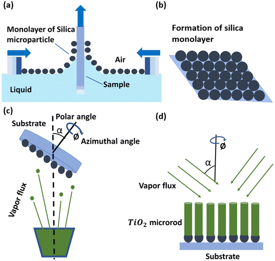
The rod-shaped micromotors are fabricated by taking advantage of dynamic shadowing growth (DSG).28–34 The schematic in Fig. 1 shows the steps involved in the fabrication. Briefly, first, a close-packed monolayer of silica particles (1 μm diameter, Micromod) was formed upon the silicon substrate using the Langmuir–Blodgett (LB) technique. For the LB technique, the silica particles were made hydrophobic by treating their surface with the allyltrimethoxysilane (Sigma Aldrich) chemical. The chemically treated microparticles were dispersed over the water surface in an LB trough to form a monolayer at the interface. The formed monolayer was transferred over the silicon (Si) substrates by slowly pulling the substrates out of the LB trough as shown in Fig. 1a. The monolayer over the silicon substrate (see Fig. 1b) acts like a seed layer for the dynamic shadowing growth. For the growth, the patterned substrate was then transferred into a high-vacuum chamber (∼10−6 Torr) consisting of a glancing angle deposition (GLAD) assisted e-beam evaporation system. The substrates were mounted on a specially designed sample holder that holds the substrates making a very high angle (86°) between the substrate normal and the direction of the incident vapor flux, and rotates (10 RPM) them in the azimuthal plane.35–37 We evaporated titanium dioxide (TiO2) in the chamber at a deposition rate of 0.1 nm s−1. The dynamic shadowing at the tilted and rotating substrates allows TiO2 to form vertical rods over the individual seeds (see Fig. 1c and d). The as-grown TiO2 is normally amorphous, and to convert it into the active anatase phase, the fabricated Janus micromotors were annealed at 450 °C for 30 min in air. The formation of the anatase phase was confirmed through powder X-ray diffraction (PXRD, Bruker D8) and UV-vis absorbance spectra (see Fig. S1, ESI†). The formation of the rod-like shape and elemental distribution over its surface were confirmed using field-emission scanning electron microscopy (Fe-SEM, Zeiss Gemini 500) imaging and energy dispersive X-ray spectroscopy (EDX) analysis, respectively.2.2 Sample preparation
Once the microrods were formed, they were transferred to an aqueous medium by sonicating the substrates in water. When they were transferred, a small amount of hydrogen peroxide (H2O2) was added to make an aqueous solution of 5% (v/v) H2O2. For changing the pH of the solution to make it basic or acidic, a small amount of diluted tetramethyl ammonium hydroxide or sulfuric acid was added, respectively.2.3 Illumination and observation
A sessile droplet of the microrods with 5% (v/v) aqueous hydrogen peroxide (H2O2) solution was deposited on a plasma-cleaned glass coverslip and the particles were allowed to sediment. The experiment was performed under a 63× objective lens arranged in the inverted geometry mode of an optical microscope (Leica DMi8). A mercury lamp (HBO 103) in an epifluorescence-type arrangement served as the light source for the photocatalytic excitation and a white LED in transmittance mode was used for the sample imaging. A set of optical filters was used to allow light of wavelengths 320 nm to 400 nm for the excitation and above 400 nm white light for the imaging of the micromotors, respectively. The intensity of excitation light was maintained at 76 mW cm−2 throughout the experiment. The images were captured at frame rates ranging from 10 to 20 fps. To calculate the Mean Squared Displacement (MSD), we recorded a video of each particle, capturing hundreds of frames within a field of view measuring approximately 125 μm × 125 μm. Particle tracking provides the position data of each particle in the captured frames. By using the data points, MSD was calculated mathematically and plotted at different time intervals.38 A self-written Python code based on the CSRT tracker provided in the Open-Source Computer Vision Library was used for tracking and measuring the speed of micromotors, and the details are provided somewhere else.172.4 Theoretical model
Section 3 of the ESI† provides the detailed mathematical formulation of the model. Briefly, we adapted a continuum model common in the active colloid literature that resolves the shape of the particle, the distribution of catalytic activity on the particle surface, and the chemical and flow fields sourced by the particle.39,40The particle is assumed to produce a chemical product (“solute”) on TiO2 at a uniform rate. Using the boundary element method, we numerically solve for the concentration of the solute . For a particle in the vicinity of a hard planar substrate (i.e., “wall”), we include the effect of the wall on
  . The interfacial gradients of the solute concentration on the particle surface are assumed to drive an interfacial fluid flow
  (“slip velocity”) via a phoretic mechanism.41 We assume Stokes flow and solve for the flow field
  and particle velocities
  and
and  numerically, including the effect of the no-slip wall. We also include the effect of gravity and a short-ranged repulsive potential between the particle and the wall.42
3. Results and discussion
3.1 Light-powered rod-shaped micromotors
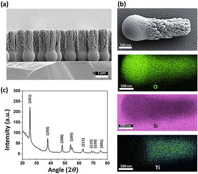
The rod-shaped micromotors are fabricated using dynamic shadowing growth (DSG). DSG occurs in the glancing angle deposition (GLAD) system, where the substrate is placed so that its normal has a very high angle (α ≥ 85°) with respect to the incident vapor flux direction.26,27 The details of the fabrication process are given in the ‘Materials and methods’ section. The fabrication technique allows the fabrication of a large number of uniform, vertically standing, and close-packed microrods of length ∼3 μm and diameter ∼1 μm over the silicon (Si) substrate. The presence of a spherical seed particle and a grown rod-like component over it can be seen in the SEM image (see Fig. 2a).The EDX mapping (see Fig. 2b) confirms the growth of TiO2 material over the silica seed particles, showing the material distribution. They can be considered as the head (silica) and tail (TiO2) parts of the microrods. Previously, it has been observed that the crystalline phase of TiO2 shows a better photo-response.12,43 Here, the post-fabrication sample treatment converts the as-grown amorphous TiO2 column into the crystalline anatase phase. The phase transformation is verified through the XRD analyses as shown in Fig. 2c. It is to be noted that the present fabrication technique allows the formation of a large number of micromotors in a single deposition. Typically, a 4-inch diameter Si substrate can be coated with micromotors at a number density of around 106 mm−2. This number suggests that a sufficient quantity of micromotors can be fabricated in a single batch that might be required for any typical application.Once the characterization is done, the rod-shaped micromotors were transferred into water through sonication for performing the experiments. The grown rod-shaped micromotors show Brownian fluctuations when immersed in an aqueous peroxide solution (5% v/v) under no light illumination. Upon turning on the UV light (320–400 nm, 76 mW cm−2 intensity), the photocatalytic decomposition of peroxide occurs on the TiO2 surface according to the reaction scheme shown in eqn (1).
 | (1) |
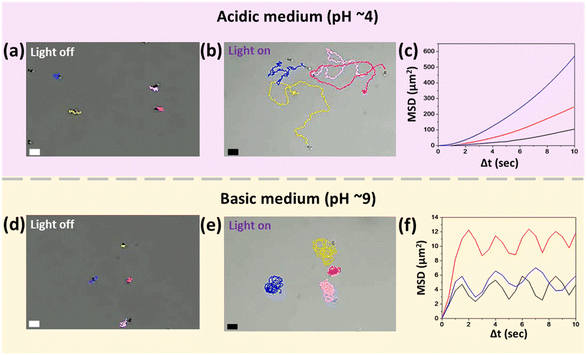
Consequently, the asymmetric chemical activity over the microrods drives the solution out of the chemical equilibrium, and the formed gradient in the surrounding chemical composition results in a self-phoretic motion of the microrods.17,21 The observed swimming behavior of the fabricated rod-shaped micromotors is discussed in the following section. Since the chemical activity over TiO2 is driven by light, the micromotors swim only when the light is turned on. Under no light, they remain idle and exhibit Brownian motion (see Fig. 3a). In addition to the light conditions, the swimming behavior of these light-driven rod-shaped micromotors is found to vary significantly upon changing the pH of the medium.
3.2 pH-Dependent dynamics of rod-shaped micromotors
The pH of the aqueous peroxide medium (5% v/v) is slightly acidic (∼5.5). In this medium, when illuminated with UV light, the micromotors swim in random directions, making long trajectories at an average speed of 3.7 ± 0.75 μm s−1. This motion can be considered translational for short ranges, because for longer times, the thermal fluctuations lead to deviations from the straight-line motion. The microscopic images show that the motion of micromotors is toward the silica head, i.e., away from the active TiO2 tail. On reducing the pH to 4, the overall swimming behavior remains the same; however, the average translational speed increases to around 4.5 ± 1.2 μm s−1, which is close to 1.5 times the body length per second (see Video S1, ESI†). The trajectories and mean square displacement (MSD) versus time interval plot of micromotors at pH 4 are shown in Fig. 3b and c, respectively. They confirm that the micromotor exhibits random trajectories with high directional persistence. In Fig. 3c, each MSD plot is for an individual micromotor produced by averaging the displacement of particles over the progression of time intervals. A detailed discussion on the nature of the MSD plot38,44 and associated features like persistence length and time scale for transition to the diffusive regime is provided in the ESI† (see section 2.3, ESI†).On increasing the pH, we initially observe a reduction in speed. Interestingly, above the neutral value, i.e., pH 7, the direction of motion is reversed, and the micromotors swim toward the active TiO2 tail, i.e., away from the inert silica head. In addition to the change in the swimming direction, on increasing the pH, it was observed that when activated, instead of making long trajectories, the micromotors remain confined to the small region around their initial positions (see Video S2, ESI†). This effect becomes more pronounced and changes into rotational motion on further increasing the pH (see Video S3, ESI†). Fig. 3e shows that the micromotors perform the rotational motion at pH 9. The MSD vs. time interval plot with multiple peaks also indicates the cyclic or rotational motion of the micromotors (see Fig. 3f). It can be noticed that, while the micromotors are rotating, thermal fluctuations or asymmetry in the shape or the flows around the micromotors may cause slight variations in the rotational path, and that is why they slightly deviate from repeating the same path around a fixed point. This is evident from the trajectories and MSD plot given in Fig. 3e and f, respectively.
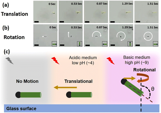
To compare the two cases, i.e., pH 4 and pH 9, the images of a micromotor moving in media at these pH values for a given time interval are shown in Fig. 4a and b, respectively. The images clearly indicate that for the given time interval, at low pH, the micromotor exhibits translational motion, while at high pH, it rotates and completes a full rotation about its own body axis. The schematic in Fig. 4c shows a cartoon representing this overall swimming behavior of the micromotors, i.e., no motion when light is turned off, translational motion under light illumination at low pH, and rotational motion under light illumination and high pH conditions (see section 2.4, ESI†). The observed direction of movement at different pH values is highlighted with the brown color arrows. At low pH, it is towards the head, while at high pH (9), it reverses toward the tail. The length of the arrows is kept different to highlight the dominating mode, i.e., translation or rotational at different pH values.
To understand the mechanisms behind this phenomenology and in particular the dependencies on the pH of the medium, in the next section, we develop and study a theoretical model that phenomenologically accounts for the pH-dependent interactions of the chemical species (reactant/product) with the micromotor's surface. These interactions govern the strength and direction of flows around them.
3.3 Theoretical model
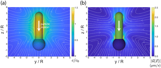
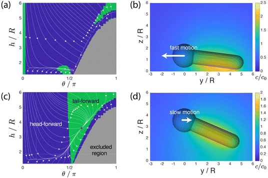
We aim to develop a simple phenomenological model that recovers the pH-dependent transition from fast “head-forward” motion, with the rod axis parallel to the substrate, to slow “tail-forward” motion, with a tilted angle of the rod axis. Our model resolves the complex shape of the particle, the difference in the material composition between the two particle segments, the chemical activity of the particle, particle-generated flows, and the effect of the confining wall. For simplicity, we assume that there is uniform, steady production of a product molecule (i.e., oxygen) over the TiO2 segment of the particle, i.e., we neglect the details of the reaction scheme in eqn (1). As discussed in detail in the ESI†, spatial variations in the product molecule concentration along the surface of the particle lead to fluid flow in a thin interfacial region, modeled as an effective slip velocity on the particle surface. This slip velocity drives the flow in the surrounding solution, leading to particle motion. Importantly, the slip velocity at a location on the particle surface is proportional to a material-dependent parameter, the so-called surface mobility. This parameter provides the details of the effective interaction between the product molecule and the particle surface.45 Here, we assume that the surface mobility takes constant values on the “head” and “tail” of the particle. Our model additionally includes the effect of gravity (force and torque) on the particle. We show that the pH-driven transition can be recovered in the model as an effective change in the surface mobilities, i.e., the particle surface chemistry. on the surface of the particle and in the surrounding fluid for a particle in unbound solution (i.e., the particle is far away from binding surfaces). In our model, the surface chemistry of the particle is parameterized by two dimensionless quantities, bi and bc, corresponding to the inert “head” and the catalytic “tail”, respectively. Specifically, they parameterize the interaction between the reaction product and the surface. When a surface mobility parameter is negative, the interaction is effectively repulsive; when it is positive, the interaction is effectively attractive. In terms of the characteristic velocity U0 (see the ESI†), we calculated that the velocity of the particle in free space is Ufs/U0 = 0.0943bi − 0.0298bc, where a positive velocity corresponds to “tail-forward” motion. Thus, negative (i.e., repulsive) bi would contribute to driving the particle in the negative z direction, away from the catalytic tail. Intuitively, for repulsive bi, the spherical head is driven away from the high concentration of the solute in the region of the tail. Likewise, positive (i.e., attractive) bc would contribute to driving the particle in the negative z direction, away from the catalytic tail. This is less intuitive, but can be understood from the fact that the solute concentration is high along the sides of the rod and low at the tip. In Fig. 5a and b, we also show the streamlines of the flow for the specific values bc = 1 and bi = 0.25. (Note that the concentration field does not depend on the values of bi and bc.) These parameters correspond to “head-forward” motion, as indicated by the large white arrows. From the pattern of streamlines, it can be inferred that the particle is a hydrodynamic “pusher” for these parameters.46 In particular, the particle draws fluid into the rod-like center region, and pushes fluid away from its two poles. The overall strength of the product/surface interaction is characterized with a characteristic surface mobility b0, which has units of m5 s−1 and contributes to the determination of U0 = |b0κ/D|, where κ is the rate of catalytic activity, and D is the diffusion coefficient of the product molecule (see the ESI†). In Fig. 5b, the background color in the fluid surrounding the particle shows the magnitude of the flow velocity for the value U0 = 160 μm s−1. Note that the velocity magnitude is on the order of μm s−1, consistent with experimental velocities. Interestingly, the flow is the strongest near the rod tip and the sphere/rod junction, indicating that these are the most important regions of the particle surface in driving particle motion. Additionally, in Fig. 5b, the colors on the surface of the particle show the catalytic region (green) and the inert region (blue).
We have shown that the transition can be reproduced in a simple phenomenological model with a simple change in parameters. Firstly, the product/particle interaction is changed from effectively attractive to effectively repulsive – but the relative magnitudes of the oxygen/silica and oxygen/titania interactions are left unchanged. In our model, this corresponds to a simple sign inversion of two parameters. Secondly, the characteristic swimming speed U0 = |b0κ/D| is reduced by a factor of five. Since a change in pH has little effect on the diffusion coefficient D of oxygen, this change in U0 corresponds to a reduction of catalytic activity, a reduction of the magnitude of the surface/product interaction, or both. We suggest that both the sign inversion and the change in U0 are consistent with a pH-induced change in the zeta potential on the surface of the particle. In this interpretation, the sign inversion corresponds to a change in the sign of the zeta potential, and a reduction of b0 (thereby reducing U0) corresponds to a change in the magnitude of the zeta potential.
The transition from a wall-parallel configuration to a tilted configuration with the sign inversion of the bi and bc parameters is consistent with the previously noted change from a hydrodynamic “pusher” to a hydrodynamic “puller”. It is known from the literature that a pusher will tend to align its axis of propulsion to be within the plane of a no-slip wall through hydrodynamic interactions with the wall. Likewise, a puller will tend to align its axis to be perpendicular to the wall.47
Our modeling also demonstrates that, to reproduce the two surface-bound “sliding” states, it is sufficient to consider only a few essential physical parameters: the particle's weight and bottom-heaviness, and the activity-induced hydrodynamic and chemical interaction of the particle with the wall. Our results do not exclude the possibility that another choice of parameters, or a more detailed model, may reproduce the same transition, or even show better quantitative agreement with the experimental data. For instance, for a more finely tuned set of “high pH” parameters (bc = −0.5, bi = −0.2, U0 = 190 μm s−1), we obtain an attractor with an even stronger tilt angle, θ = 139°, and a slow velocity of |Uy| = 0.53 μm s−1, as shown in Fig. S2 (ESI†).† As an example of more detailed physics omitted from our model, we did not consider the chemiosmotic slip at the wall. Consideration of this effect could improve quantitative agreement with the experimental data but would introduce another free parameter (the surface mobility of the wall). Overall, our aim was to reproduce the steady states and the transition between them in the framework of a minimally featured model. The minimalism of our model suggests that pH-induced transitions between sliding states may be a generic phenomenon in active colloidal systems.
We briefly comment on the implications of our model for the interpretation of the data in Nicholls et al.'s study. Nicholls et al. hypothesize that a reversal in the direction of motion with changing tail length is due to the role of chemiosmotic flow on the wall. In the present study, for simplicity, we neglected the consideration of this chemiosmotic flow. Nevertheless, in the framework of our model, we find that it is possible to obtain a reversal of direction with a change of tail length for a particle in unbound solution (ESI Fig. S5†). On the other hand, for the tail lengths considered, this reversal effect occurs only within a relatively narrow band of surface mobility parameters. Overall, these findings point to the need for further studies that combine experiments and theoretical modeling in order to unravel the dependence of motion reversal and other phenomena on the various physical mechanisms that contribute to particle propulsion.
4. Conclusion
We have designed simple rod-shaped micromotors that can be fabricated inexpensively and very easily by using the dynamic shadowing growth (DSG) technique, and also large quantities can be obtained simultaneously. The structure comprises a TiO2 microrod (2 μm) over a SiO2 microsphere (1 μm diameter) which is activated through low intensity (76 mW cm−2) UV light (320–400 nm) illumination in an aqueous peroxide medium. Interestingly, the micromotors exhibit multimode swimming behavior based on the pH of the medium. At lower pH (acidic ∼ 4), they show translatory motion with the swimming direction towards the silica head. On increasing the pH to around 9 (basic), they switch to rotational motion with the swimming direction reversed to the tail (TiO2) side. The trajectories of motion and the mean square displacement (MSD) plots confirm the observed multimode swimming behavior of the micromotors in different pH media under UV light exposure. The pH-dependent multimode swimming has been rationalized using a theoretical model incorporating chemical activity, hydrodynamic flow, and the effect of gravity for a rod-shaped active particle near a planar wall. Experimental studies combined with theoretical modeling provides valuable insights into the role of the micromotor's structure, its surface properties, chemical activity, and the surrounding pH environment. This knowledge can be leveraged to optimize the design and performance of micromotors, tailoring them for specific applications in the field of environmental monitoring, lab-on-a chip devices, and microfluidics, and improving their overall efficiency.Author contributions
D. P. S. conceptualized the problem statement; S. D. performed the experiments; S. D., S. K. P., and S. T. analyzed the data; W. U. conceptualized and performed the theoretical modeling; S. D., S. K. P., W. U., and D. P. S. wrote the manuscript. Credits: Srikanta Debata: investigation (lead), methodology (equal), validation (lead), writing – original draft (lead), and writing – review & editing (lead); Suvendu Kumar Panda: formal analysis (supporting), investigation (supporting), and writing – original draft (supporting); Satyaprakash Trivedi: formal analysis (supporting) and investigation (supporting); William Uspal: theoretical investigation (lead), conceptualization (supporting), writing – original draft (supporting), and writing – review & editing (supporting); Dhruv Pratap Singh: conceptualization (lead), investigation (supporting), methodology (supporting), project administration (lead), resources (lead), supervision (lead), writing – original draft (supporting), and writing – review & editing (supporting).Conflicts of interest
The authors declare that they have no conflicts of interest.Acknowledgements
Funding support by the SERB through the startup research grant (SRG/2020/001885) is greatly acknowledged. The authors SD and SP are grateful to MHRD, India for its financial support. We gratefully acknowledge technical support and advanced computing resources from University of Hawaii Information Technology Services – Cyberinfrastructure, funded in part by the National Science Foundation, Campus Cyberinfrastructure awards #2201428 and #2232862.References
- W. Gao and J. Wang, Nanoscale, 2014, 6, 10486–10494 RSC.
- J. Palacci, S. Sacanna, A. Vatchinsky, P. M. Chaikin and D. J. Pine, J. Am. Chem. Soc., 2013, 135, 15978–15981 CrossRef CAS PubMed.
- S. K. Panda, N. A. Kherani, S. Debata and D. P. Singh, Mater. Adv., 2023, 4, 1460–1480 RSC.
- X. Peng, M. Urso, M. Ussia and M. Pumera, ACS Nano, 2022, 16, 7615–7625 CrossRef CAS PubMed.
- A. Ziepke, I. Maryshev, I. S. Aranson and E. Frey, Nat. Commun., 2022, 13, 6727 CrossRef CAS PubMed.
- K. K. Dey and A. Sen, J. Am. Chem. Soc., 2017, 139, 7666–7676 CrossRef CAS PubMed.
- A. Zöttl and H. Stark, J. Phys.: Condens. Matter, 2016, 28, 253001 CrossRef.
- S. Palagi, D. P. Singh and P. Fischer, Adv. Opt. Mater., 2019, 7, 1900370 CrossRef.
- J. G. Lee, A. Al Harraq, K. J. M. Bishop and B. Bharti, J. Phys. Chem. B, 2021, 125, 4232–4240 CrossRef CAS PubMed.
- S. Yu, N. Ma, H. Yu, H. Sun, X. Chang, Z. Wu, J. Deng, S. Zhao, W. Wang, G. Zhang, W. Zhang, Q. Zhao and T. Li, Nanomaterials, 2019, 9, 1672 CrossRef CAS PubMed.
- C. Dillinger, N. Nama and D. Ahmed, Nat. Commun., 2021, 12, 6455 CrossRef CAS PubMed.
- D. P. Singh, W. E. Uspal, M. N. Popescu, L. G. Wilson and P. Fischer, Adv. Funct. Mater., 2018, 28, 1706660 CrossRef.
- B. Dai, J. Wang, Z. Xiong, X. Zhan, W. Dai, C.-C. Li, S.-P. Feng and J. Tang, Nat. Nanotechnol., 2016, 11, 1087–1092 CrossRef CAS PubMed.
- B. Yigit, Y. Alapan and M. Sitti, Soft Matter, 2020, 16, 1996–2004 RSC.
- S. Palagi and P. Fischer, Nat. Rev. Mater., 2018, 3, 113–124 CrossRef CAS.
- V. Garcia-Gradilla, J. Orozco, S. Sattayasamitsathit, F. Soto, F. Kuralay, A. Pourazary, A. Katzenberg, W. Gao, Y. Shen and J. Wang, ACS Nano, 2013, 7, 9232–9240 CrossRef CAS PubMed.
- S. Debata, N. A. Kherani, S. K. Panda and D. P. Singh, J. Mater. Chem. B, 2022, 10, 8235–8243 RSC.
- K. Selvig and J. A. Alspaugh, Mycobiology, 2011, 39, 249–256 CrossRef CAS PubMed.
- P. A. Lund, D. De Biase, O. Liran, O. Scheler, N. P. Mira, Z. Cetecioglu, E. N. Fernández, S. Bover-Cid, R. Hall, M. Sauer and C. O'Byrne, Front. Microbiol., 2020, 11, 556140 CrossRef PubMed.
- N. M. Martinez-Rossi, G. F. Persinoti, N. T. A. Peres and A. Rossi, Mycoses, 2012, 55, 381–387 CrossRef CAS PubMed.
- D. P. Singh, U. Choudhury, P. Fischer and A. G. Mark, Adv. Funct. Mater., 2017, 29, 1701328 Search PubMed.
- N. Möller, S. Seiffert, T. Palberg and R. Niu, ChemNanoMat, 2021, 7, 1145–1160 CrossRef.
- N. Möller, B. Liebchen and T. Palberg, Eur. Phys. J. E, 2021, 44, 41 CrossRef PubMed.
- J. Zhuang, R. W. Carlsen and M. Sitti, Sci. Rep., 2015, 5, 11403 CrossRef PubMed.
- S. Heckel and J. Simmchen, Advanced Intelligent Systems, 2019, vol. 1, p. 1900093 Search PubMed.
- B. Ai and Y. Zhao, Nanophotonics, 2018, 8, 1–26 CrossRef.
- M. T. Taschuk, M. M. Hawkeye and M. J. Brett, Handbook of Deposition Technologies for Films and Coatings, Elsevier, 2010, pp. 621–678 Search PubMed.
- Y.-P. Zhao, D.-X. Ye, G.-C. Wang and T.-M. Lu, Nano Lett., 2002, 2, 351–354 CrossRef CAS.
- Y. He and Y. Zhao, Nanoscale, 2011, 3, 2361 RSC.
- J. G. Gibbs and P. Fischer, Chem. Commun., 2015, 51, 4192–4195 RSC.
- P. Fischer and A. Ghosh, Nanoscale, 2011, 3, 557–563 RSC.
- D. P. Singh and J. P. Singh, Appl. Phys. A, 2014, 114, 1189–1193 CrossRef CAS.
- D. P. Singh, S. Kumar and J. P. Singh, RSC Adv., 2015, 5, 31341–31346 RSC.
- C. M. Maier, M. A. Huergo, S. Milosevic, C. Pernpeintner, M. Li, D. P. Singh, D. Walker, P. Fischer, J. Feldmann and T. Lohmüller, Nano Lett., 2018, 18, 7935–7941 CrossRef CAS PubMed.
- J. G. Gibbs and Y.-P. Zhao, Small, 2009, 5, 2304–2308 CrossRef CAS PubMed.
- P. Basnet and Y. Zhao, J. Mater. Chem. A, 2014, 2, 911–914 RSC.
- S. Ghosh and A. Ghosh, Nat. Commun., 2019, 10, 4191 CrossRef PubMed.
- G. Dunderdale, S. Ebbens, P. Fairclough and J. Howse, Langmuir, 2012, 28, 10997–11006 CrossRef CAS PubMed.
- R. Golestanian, T. B. Liverpool and A. Ajdari, New J. Phys., 2007, 9, 126–126 CrossRef.
- W. E. Uspal, M. N. Popescu, S. Dietrich and M. Tasinkevych, Soft Matter, 2015, 11, 434–438 RSC.
- J. L. Moran and J. D. Posner, Annu. Rev. Fluid Mech., 2017, 49, 511–540 CrossRef.
- A. Rashidi, S. Razavi and C. L. Wirth, Phys. Rev. E, 2020, 101, 042606 CrossRef CAS PubMed.
- R. Dong, Q. Zhang, W. Gao, A. Pei and B. Ren, ACS Nano, 2016, 10, 839–844 CrossRef CAS PubMed.
- J. R. Howse, R. A. L. Jones, A. J. Ryan, T. Gough, R. Vafabakhsh and R. Golestanian, Phys. Rev. Lett., 2007, 99, 048102 CrossRef PubMed.
- J. J. Anderson and L. John, Annu. Rev. Fluid Mech., 1989, 21, 61–99 CrossRef.
- D. Saintillan, Annu. Rev. Fluid Mech., 2018, 50, 563–592 CrossRef.
- S. E. Spagnolie and E. Lauga, J. Fluid Mech., 2012, 700, 105–147 CrossRef.
- D. Nicholls, A. DeVerse, R. Esplin, J. Castañeda, Y. Loyd, R. Nair, R. Voinescu, C. Zhou, W. Wang and J. G. Gibbs, ACS Appl. Mater. Interfaces, 2018, 10, 18050–18056 CrossRef CAS PubMed.
Footnote |
| † Electronic supplementary information (ESI) available: Videos S1–S3 and Fig. S1–S5. See DOI: https://doi.org/10.1039/d3nr03775d |
| This journal is © The Royal Society of Chemistry 2023 |

