pH-controlled assembling of POM-based metal–organic frameworks for use as supercapacitors and efficient oxidation catalysts for various sulfides†
Yujiao
Hou
 *,
Peilin
Han
,
Like
Zhang
,
Hao
Li
and
Zhihong
Xu
Key Laboratory of Chemo/Biosensing and Detection, College of Chemical and Materials Engineering, Xuchang University, Xuchang 461000, P. R. China. E-mail: Houyj@xcu.edu.cn
First published on 8th November 2022
Abstract
The development of electrode materials for supercapacitors is a significant issue for future energy storage devices. In addition, the selective oxidation of sulfides to sulfoxides that serve as key intermediates for synthesizing medically and chemically active molecules is still a critical challenge. In this study, two novel 3D POM-based metal–organic frameworks, formulated as [Cu3(bty)3][BW12O40]·4H2O (1) and [Cu2.5(bty)5][BW12O40]·7H2O (2) (bty = bis(1,2,4-triazol-1-yl)ethane), were obtained via a one-step synthesis strategy by adjusting the pH value under solvothermal conditions. In compound 1, {BW12} as a 2-connected node is located between 2D Cu–organic sheets to yield a novel 3D POM-based metal–organic framework. There are 1D channel structures constructed with Cu–organic sheets in compound 2. Then, {BW12} as a 4-connected node merged into the orifice of the Cu–organic framework forming a glamorous 3D framework. Moreover, the 3D Cu–organic framework of 2 displays the fascinating shape of vase structures. These two compounds could be applied as electrode materials for supercapacitors with specific capacitances of 214.59 F g−1 and 189.17 F g−1 at 0.48 A g−1 respectively, as well as efficient heterogeneous catalysts for selective oxidation of sulfides to their corresponding sulfoxides.
1 Introduction
Supercapacitors (SCs) play an important role in energy storage systems, which is mainly due to their high capability, remarkable cycle life and low cost, attracting increasing attention for meeting the low-carbon and sustainable economy.1–5 However, electrode materials suffer from a major disadvantage of shortage of energy density, which is far from satisfying the practical application requirements of large-scale energy storage systems. Therefore, searching for high-energy density electrode materials is meaningful to satisfy future energy demands for practical applications.Polyoxometalates (POMs), a unique class of multimetal oxide clusters, have been regarded as prospective electrode materials for SCs, which is mainly owing to their abundant electron storage capacity, considered as “electron sponge”, peculiar electrochemical behavior and high acidic stability. In light of this, much effort has been contributed to investigate the application of electrode materials based on POMs.6,7 Unfortunately, the intrinsic drawbacks of POMs such as low conductivity, smaller superficial area and high solubility, easily resulting in poor cycling life, limit their practical applications as electrode materials for SCs. Thus, it was still a big challenge to design and fabricate POMs to obtain excellent electrode materials with remarkable cycle stability and superior specific capacitance. To overcome these defects, one of the approaches is assembling from POMs and various host materials such as carbon nanoparticles, grapheme, carbon nanotubes, TiO2 and polypyrrole, improving the stability and increasing the energy density of the POM-based electrode material.8–14 Another efficient strategy is the incorporation of POMs into a metal–organic framework to obtain POM-based metal–organic frameworks. This approach can combine the advantages of POMs and metal–organic frameworks; meanwhile, POMs can also change the equilibriums between metal cations and organic ligands to affect the reaction and further control the nucleation and resulting shape and structure. Based on the above-mentioned analysis, the combination of some classic-type POMs {XM12}(X = Si, P, As or B; M = W or Mo) with a metal–organic framework, has been obtained and applied to the application of electrode materials.15–19 These investigations verify that the combination of POMs with metal–organic frameworks can enhance the stability and improve the electrochemical capability of electrode materials.
Additional, oxidative transformation of sulfides into their homologous sulfoxides and sulfones is also a meaningful issue for their widespread application in the preparation of medically and chemically active molecules.20–29 As we know, POMs have been extensively applied to catalyze various organic substrates because of their unique redox performances and high thermal stability. In the oxidation of sulfides, some homogeneous catalysts based on POMs, such as [H2N(CH3)2]14[As4W40O140{Ru2(CH3COO)}2]·22H2O, TBA4H2[BW11Mn(H2O)O39]·H2O, and [(CH3)4N]4[{Re(CO)3}4(Mo4O16)]·H2O, have been investigated and display excellent catalytic activity.30–32 Although the above-mentioned catalysts exhibit remarkable catalytic performance, intrinsic drawbacks such as high solubility and difficult separation of these catalytic system restrict their further applications and investigations. To solve the recyclable issue, one alternative approach is to anchor the POMs to a proper carrier such as metal–organic frameworks. In 2021, Liu et al. have isolated a POM-based metal–organic framework (POV-MOF), [Ni(bix)2]{V4O11} (bix = 1,4-bis(imidazol-1-ylmethyl)benzene), which can efficiently catalyze various sulfides to their corresponding sulfones under mild conditions.33 In the above-mentioned study, the reason for the high catalytic oxidation activity was also investigated via density functional theory (DFT) calculations, which is mainly attributed to the vanadium cluster. Recently, An's group successively obtained several POMOFs, {[ε-PMoV8MoVI4O37(OH)3][Zn2(C10N2H8)(H2O)2]2}2·8H2O and TBA2H2[Zn4(im)(Him)2][ε-PMoV8MoVI4O40·3H2O (Him = 1H-imidazole), which exhibited excellent catalytic performances for the selectivity oxidation of various sulfides.34,35 Thus, it can be seen that investigators have been seeking higher activity catalysts based on POMs for the selectivity oxidation of multifarious sulfides to their homologous sulfoxides and sulfones.
The above-mentioned analysis revealed that POM-based metal–organic frameworks exhibit excellent electrochemical performance and catalytic activity. Inspired by this idea, we expect the combination of POMs and metal–organic frameworks to yield novel structures and fabulous electrochemical and catalytic performances. In this study, we adopted Keggin-type POMs {BW12} as templates, Cu ions as metallic nodes and bis(1,2,4-triazol-1-yl)ethane (bty) as the multidentate bridging ligand to isolate two novel crystal materials, namely [Cu3(bty)3][BW12O40]·4H2O (1) and [Cu2.5(bty)5][BW12O40]·7H2O (2). Both compounds display 3D frameworks, in which {BW12} polyoxoanions are located between the 2D Cu–organic sheets in compound 1. In compound 2, {BW12} polyoxoanions are situated in the channels of Cu–organic frameworks. It is remarkable that the Cu–organic frameworks of 2 exhibit the beautiful shape of vase structures. The two compounds were used for the electrode materials and selective oxidation of various sulfides. The results indicated that both compounds not only exhibited excellent electrochemical performance as electrode materials for SCs but also displayed good activity as heterogeneous catalysts for the selectivity oxidation of sulfides.
2 Experimental sections
2.1 Synthesis of [Cu3(bty)3][BW12O40]·4H2O 1
The precursor K5BW12O40·xH2O was synthesized according to the procedure reported in the literature.36 CuCl2 (0.3 mmol), K5BW12O40·xH2O (0.05 mmol) and bty (0.05 mmol) were mixed together in a mixed solution of H2O (10 mL) and ethanol (4 mL), and stirred for 30 min. The pH value of the mixture was adjusted to 2.5 with diluted HCl. Then, the resulting suspension was stirred for another 30 min, which was decanted into a 30 mL Teflon-lined steel autoclave and maintained at 150 °C for 5 days. Green strip-shaped crystals were obtained by filtration and washed with distilled water. The yield is 35% based on K5BW12O40·xH2O. Elemental analyses found (calcd) for C18H32BCu3N18O48W12 (M = 3676.16): C, 5.88 (6.02); H, 0.88 (0.92); Cu, 5.19 (5.42); B, 0.29 (0.25); W, 60.00 (60.35). IR (KBr pellet): 3429(s), 3126(w), 1621(m), 1535(s), 1436(m), 1381(w), 1296(s), 1225(w), 1139(s), 999(s), 995(s), 821(s), 666 (w), 530(w) cm−1.2.2 Synthesis of [Cu2.5(bty)5][BW12O40]·7H2O 2
The synthetic method of complex 2 was analogous to complex 1 except for adjusting the pH value of the mixed solution to 4.4. After 5 days, blue bulk crystals were obtained by cooling to room temperature and the rate of production of 2 is 30% (based on K5BW12O40·xH2O). Elemental analyses found (calcd) for C30H44BCu2.5N30O47W12 (M = 3952.81): C, 9.12 (9.62); H, 1.20 (1.52); Cu, 4.02 (4.32); B, 0.27 (0.25); W, 55.80 (55.35). IR (KBr pellet): 3450(s), 3120(w), 1623(m), 1530(s), 1441(w), 1370(w), 1285(s), 1215(m), 1129(s), 998(m), 950(s), 900(m), 821 (s), 652 (w), 528(w) cm−1.2.3 General methods of electrochemical measurements
The electrochemical performance was examined on a CHI660E electrochemical workstation using 0.1 M H2SO4 solution in a usual three-electrode system. The working electrodes were prepared by a mixture of compound 1 or 2, graphite powder and polyvinylidene fluoride (PVDF) in a certain ratio, which was ground in an agate mortar for 0.5 h and coated onto the treated carbon cloth (CC). The CC was pretreated based on the reported method.37 Then, the CC was dried under vacuum after the addition of 100 μL of N-methylpyrrolidone. The Ag/AgCl (3 M KCl) electrode acted as the reference electrode and a Pt wire as the counter electrode.2.4 General methods of the selective oxidation of methyl phenyl sulfide (MPS)
MPS oxidation: MPS (0.25 mmol), catalyst (2 μmol), oxidant (30% H2O2, 0.4 mmol), internal standard (naphthalene, 0.25 mmol) and solvent (methanol: 0.5 mL) were mixed in the reaction vessel. The catalytic reaction was carried out at 45 °C. After the catalytic reaction was finished, gas chromatography (GC) and gas chromatography-mass spectrometry (GC-MS) were used to analyze and identify the resulting mixture.3 Results and discussion
3.1 Syntheses and characterization
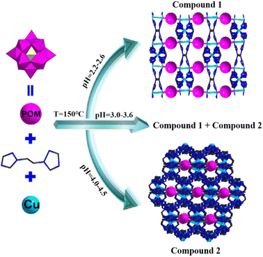
The selection of appropriate metal ions or organic ligands and suitable conditions is the key to the establishment of novel POM-based metal–organic frameworks. Among these derivatives, 3D crystalline inorganic–organic hybrid complexes are especially attractive for their novel structures and widespread applications. For this purpose, we attempt to introduce the Cu–organic complex into the {BW12O40} system to obtain a hybrid derivative. Compounds 1 and 2 were solvothermally synthesized from the reactions of Keggin-type polyanions [BW12O40]5−, bty ligands and Cu2+ in a blended solvent of H2O and ethanol at pH values of 2.5–4.5 (Scheme 1). A large number of parallel experiments without ethanol were also performed; however, no corresponding crystals were obtained, which indicated that the solvent was important in the construction of compounds 1 and 2. In addition, the pH values were also significant for building these compounds. To investigate the influence of pH, a lot of parallel experiments were conducted. We repeated the experiments at 0.05 interval of the pH value from 1 to 7 between two parallel experiments. Detailed experiments show that compound 1 can be synthesized at pH values of 2.2 to 2.6, whereas compound 2 requires a little high pH value (4–4.5); moreover, compounds 1 and 2 were obtained at the same time at pH ranging from 3.0 to 3.6. In addition, at the pH ranging from 2.5 to 3.0 or 3.6 to 4.0, very few crystals and more precipitates were obtained. In the parallel reaction system, transition metal ions (Co2+/Ni2+/Mn2+/Cd2+) and rare earth ions (La3+/Ce3+/Nd3+/Gd3+) were also introduced into the reactions, no similar corresponding compounds were obtained, and only some low dimension structures were obtained, which will also be reported in the subsequent articles. In the meantime, when other Keggin-type polyanions replaced {BW12O40} such as {PW12O40}, {PMo12O40} and {SiW12O40}, only some reported low-dimension compounds were obtained. In a word, reaction conditions (solvent or pH values), metal ions, organic ligands and POM anions play crucial roles in the establishment of POM-based metal–organic frameworks.IR spectra of two compounds are displayed in Fig. S1,† the characteristic vibrational bonds of B–O, W![[double bond, length as m-dash]](https://www.rsc.org/images/entities/char_e001.gif) O and W–O are around 998, 951, 901, 882, 635 and 530 cm−1, respectively. The peaks of 1624, 1530, 1441, 1371, 1286, 1214 and 1129 cm−1 are ascribed to C–C, C–N, N–N, C–H and N–H vibrations of the organic ligands bty. Fig. S2† exhibits the diffuse reflectance spectra of two compounds, the UV region (200–400 nm) exists several absorption peaks, 225, 255, and 290 nm for 1, 218, 248, 292 and 390 nm for 2, which are assigned to O → W charge transfer. One absorption bond distributed in the visible region is ascribed to the electronic transition of POMs. The PXRD patterns and the calculated peaks of two compounds indicate the phase purities (Fig. S3†). The TGA proves that two compounds successively miss lattice and coordinated water, and organic ligands bty from 30 to 750 °C (Fig. S4†). In addition, compounds 1 and 2 were also verified by SEM, EDS and EDX (Fig. S5 and S6†). The elemental mapping (Fig. S5c–h and S6c–h†) indicates the uniform distribution of W, O, C, Cu, N and B throughout the compounds, which is in consistent with energy-dispersive X-ray spectrometry (Fig. S5b and S6b†).
O and W–O are around 998, 951, 901, 882, 635 and 530 cm−1, respectively. The peaks of 1624, 1530, 1441, 1371, 1286, 1214 and 1129 cm−1 are ascribed to C–C, C–N, N–N, C–H and N–H vibrations of the organic ligands bty. Fig. S2† exhibits the diffuse reflectance spectra of two compounds, the UV region (200–400 nm) exists several absorption peaks, 225, 255, and 290 nm for 1, 218, 248, 292 and 390 nm for 2, which are assigned to O → W charge transfer. One absorption bond distributed in the visible region is ascribed to the electronic transition of POMs. The PXRD patterns and the calculated peaks of two compounds indicate the phase purities (Fig. S3†). The TGA proves that two compounds successively miss lattice and coordinated water, and organic ligands bty from 30 to 750 °C (Fig. S4†). In addition, compounds 1 and 2 were also verified by SEM, EDS and EDX (Fig. S5 and S6†). The elemental mapping (Fig. S5c–h and S6c–h†) indicates the uniform distribution of W, O, C, Cu, N and B throughout the compounds, which is in consistent with energy-dispersive X-ray spectrometry (Fig. S5b and S6b†).
3.2 Crystal structures
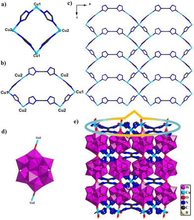
Compounds 1 and 2 are composed of the same Keggin building block, [BW12O40]5−, metal ions Cu and bty ligands; however, single-crystal X-ray diffraction analysis reveals that these two compounds pertain to different space groups. Compound 1 belongs to the Pccn space group of the orthorhombic system. The intrinsic unit of compound 1 includes half one polyoxoanion [BW12O40]5−, one and half one Cu ions and bty ligands (Fig. S7†). In compound 1, two crystallographically independent Cu centers show different coordination geometries, Cu1 adopts a four coordinated “tetrahedral” geometry with four N atoms from two bty ligands with bond distances Cu–N 1.976(3)–2.048(3) Å and angle N–Cu–N of 102.2(18)–115.1(18)°; Cu2 employed a six-coordinated “octahedral” geometry with three N atoms from three different bty ligands (Cu–N 2.002(3)–2.068(4) Å, N–Cu–N of 93.1(14)–169.8(15)°), one O atom from [BW12O40]5−, and two coordinated water (Cu–O 2.010(3)–2.588, O–Cu–O of 80.1(14)–160.1(11)°, O–Cu–N of 88.3(13)–169.2(13)°) (Fig. S8†). In addition, the bty ligands adopt tridentate and bidentate coordination modes (Fig. S9†). Owing to the diversity coordination modes of bty ligands and Cu ions, adjacent Cu ions are connected by bridging bty ligands to construct two different cyclic structures. Two Cu1 and two Cu2 are joined together with four bridging bty ligands to construct a four-membered ring {Cu4bty4} (Fig. 1a). Two Cu1 and four Cu2 are linked together with six bridging bty ligands to form another six-membered ring {Cu6bty6} (Fig. 1b).Interestingly, the same subunits {Cu4bty4} connected by sharing Cu1 ions constructed a Cu-bty chain in compound 1 (Fig. S10a†). Other subunits {Cu6bty6} are jointed together by sharing Cu2 ions to form a different Cu-bty chain (Fig. S10b†). Another interesting feature is that two neighbouring different Cu-bty chains are further joined together by sharing Cu2 ions to produce a 2D coordination complex layer along the b axis (Fig. 1c). Furthermore, the {BW12} polyanion joins two Cu2 ions from two {Cu6bty6} subunits via O atoms located on the {BW12} (Fig. 1d). Then, the 2D Cu–organic sheets are further connected through Keggin-type polyoxoanion {BW12} to yield the 3D POM-based metal–organic framework (Fig. 1e).
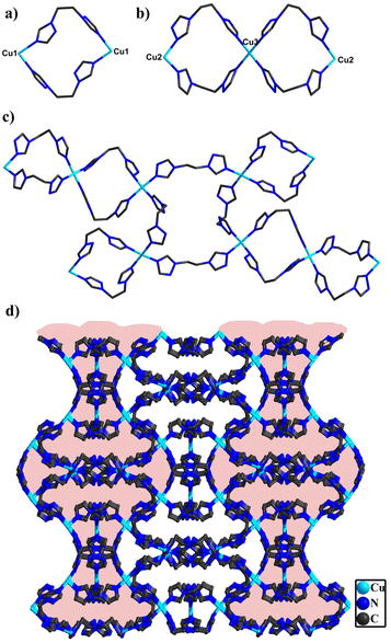
In compound 2, single-crystal X-ray diffraction analysis manifests that 2 belongs to the C2/c space group of the monoclinic system. The asymmetric structural unit is made up of two half one crystallographically independent polyanion [BW12O40]5−, two and half one Cu ions and five bty ligands (Fig. S11†). Three Cu centers all adopt a six-coordinated “octahedral” geometry and are defined by two O atoms from [BW12O40]5− and coordinated water (Cu–O 2.368(2)–2.460(2) Å, O–Cu–O of 91.2(9)–172.7 (7)°) and four N atoms from four different bty ligands (Cu–N 1.980(2)–2.046(3) Å, N–Cu–N of 86.8(11)–172.2(12)°) (Fig. S12†). Additionally, the bty ligands are employed in three different bidentate ligands (Fig. S13†). Despite holding similar coordination modes of Cu ions and bty ligands, they can be joined together to form different subunits. Two Cu1 ions are connected by bridging bty ligands and a two-membered ring {Cu2bty2} was constructed (Fig. 2a). Two Cu2 and one Cu3 are joined together by four bty ligands to form two three-membered rings {Cu3bty4} (Fig. 2b). In addition, two Cu1 and two Cu2 can be combined together with four bridging ligands to yield a four-membered ring {Cu4bty4} (Fig. S14†).
Significantly, the adjacent subunits {Cu2bty2} and {Cu3bty4} were connected via bty linkage to form a Cu-bty chain (Fig. S15†). The neighbouring 1D Cu-bty chains can be further combined with another subunits {Cu4bty4} to shape a 2D Cu-bty layer (Fig. 2c). Surprisingly, parallel 2D layers bridged the Cu-bty linkage, generating a 3D structure with several features (Fig. 2d). In the pilotaxitic 3D framework, the outline of a vase can be clearly observed. From another orientation, there are large 1D channels in which symmetrical {BW12} polyoxoanions are occupied and linked with four Cu ions (two Cu1 and two Cu2) of 3D Cu-bty MOFs (Cu–organic frameworks built by Cu ions and bty ligands) as inorganic ligands (Fig. 3 and S16†).
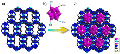 | ||
| Fig. 3 (a) View of the 3D framework constructed from Cu–organic ligands. (b) View of tetracapped polyoxoanion {BW12Cu4}. (c) View of the 3D POM-based metal–organic framework. | ||
Bond valence sum (BVS) calculations manifest that B and W atoms display the oxidation states of +3 and +6 in compounds 1 and 2. Two Cu ions are +2 oxidation states and one Cu ion is +1 oxidation state in compound 1 and all Cu ions display +2 oxidation states in compound 2, which are proved by XPS, BVS and charge balance (Fig. S17†).
3.3 Capacitive performance of compounds 1 and 2
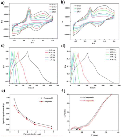
In view of their excellent supercapacitor performance, a large of POM-based compounds have been investigated. Hence, compounds 1 and 2 as electrode materials were also studied, which were evaluated by cyclic voltammetry (CV), galvanostatic charge/discharge (GCD), and electrochemical impedance spectroscopy (EIS). As a result, they displayed good electrochemical behaviors as electrode materials.The electrochemical capability of compounds 1 and 2 was tested in a three-electrode system with 0.1 M H2SO4 aqueous solution. The CV curves are exhibited in Fig. 4a and b, which were measured in the potential voltage window ranging from −0.25 to 0.6 V based on the correlational research. According to the CV curves, compounds 1 and 2 displayed good faradaic capacitive characteristics with two obvious pairs of redox peaks, suggesting that the two compounds can be regarded as electrode materials for pseudocapacitance (Fig. 4a and b).
CV curves scarcely change significantly, though the increase in scan rate generates the obvious increase in current intensities, indicating that these two electrode materials hold high capabilities. In addition, the half-wave potentials of redox peaks E1/2 = (Epa + Epc)/2 are 0.05 V and 0.32 V for 1 and 0.03 V and 0.33 V for 2. The redox peaks of compound 1 observed at 0.40–0.24 V and 0.11–0.01 V at 20 mV are ascribed to two reversible one-electron peaks originating from the WVI/WV centers in the {BW12} subunit (BW12O405− + 6e− + 5H+ = HBW12O406−, and BW12O406− + 6e− + 5H+ = H2BW12O407−), respectively,15,38 which compared the CV curves of empty glassy carbon electrodes (Fig. S18†). Meanwhile, the scan rate and redox peak exhibit a good linear relationship, which manifests that the redox system is surface-controlled and the two compounds can be good capacitor-type materials (Fig. S19†). Moreover, the current (i) and scan rate (v) comply with the following relationship:
| i = avb | (1) |
log![[thin space (1/6-em)]](https://www.rsc.org/images/entities/char_2009.gif) i = log i = log![[thin space (1/6-em)]](https://www.rsc.org/images/entities/char_2009.gif) a + b a + b![[thin space (1/6-em)]](https://www.rsc.org/images/entities/char_2009.gif) log log![[thin space (1/6-em)]](https://www.rsc.org/images/entities/char_2009.gif) v v | (2) |
![[thin space (1/6-em)]](https://www.rsc.org/images/entities/char_2009.gif) i vs. log
i vs. log![[thin space (1/6-em)]](https://www.rsc.org/images/entities/char_2009.gif) v. In theory, the electrochemical process is mainly assigned to the faradaic insertion process. While the value of b is 1.0, the process of the current belongs to the capacitive-controlled relation. Just as in Fig. S20,† both the capacitive controlled and faradaic insertion process exist in the electrode process according to b = 0.81. In order to evaluate the capacitive controlled charge storage contributions, the current (i) and scan rate (v) also comply with the following equation:
v. In theory, the electrochemical process is mainly assigned to the faradaic insertion process. While the value of b is 1.0, the process of the current belongs to the capacitive-controlled relation. Just as in Fig. S20,† both the capacitive controlled and faradaic insertion process exist in the electrode process according to b = 0.81. In order to evaluate the capacitive controlled charge storage contributions, the current (i) and scan rate (v) also comply with the following equation:| i(V) = k1v + k2v1/2 | (3) |
In addition, it can be rearranged for analytical purpose:
| i(V)/v1/2 = k1v1/2 + k2 | (4) |
In eqn (3), k1v belong to the capacitive process and k2v1/2 correspond to the faradaic insertion process, respectively. The value of k1 and k2 can be obtained through the linear fitting in eqn (4). Fig. S20† displays the capacitive and faradaic contribution of compound 1 at different scan rates, which indicates that the capacitive contribution increases from 50.7% to 75.9% with the increase in scan rates from 2 to 20 mV s−1.39–41
To further investigate the capacitive properties of the two compounds, GCDs were also carried out in a 0.1 M H2SO4 aqueous solution within the identical voltage ranging from −0.25 to 0.6 V, at diverse current densities to access their electrochemical capacitive performance (Fig. 4c and d). The evident bending slop lines of the GCD curves caused by the faradaic redox processes of two electrodes manifest the characteristics of pseudocapacitive materials. Additionally, the specific capacitances calculated by the equation C = I × Δt/m × ΔV are 214.59, 173.23, 145.29, 127.41 and 114.01 F g−1 at current densities of 0.48, 0.95, 1.90, 2.85 and 4.76 A g−1, respectively, for 1-based electrode materials and 189.17, 165.41, 140.82, 120.70, and 106.40 F g−1 for 2-based electrode materials at the identical current densities. Furthermore, the specific capacitance of the 1-based electrode material is a little higher than that of the 2-based electrode material, as observed from Fig. 4e, which is also comparable to those of the reported POM-based electrode materials listed in Table S1.†
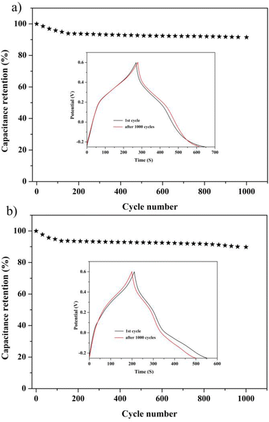
To get a further understanding of the electrochemical performance of two electrode materials, EIS of compounds 1 and 2 were measured, as shown in Fig. 4f. One can easily observe that the 1-based electrode possesses lower ohmic resistance than that of the 2-based electrode. In addition, the equivalent circuit displayed in Fig. S21† can be applied to fit the impedance spectra, the two semicircles are ascribed to charge-transfer resistance (R2 and R3) from POM-based metal–organic frameworks (1 and 2), and the Warburg resistance (Ws) locates in the tail line.13,14 Meanwhile, the life and stability of two electrodes as the electrochemical capacitors were evaluated by proceeding multiple charge–discharge cycle tests. The capacitance retention rates of two electrode materials can still remain at 91.55% and 90.2% after 1000 cycles, which can clearly indicate that two electrodes display still better capacitance retention, as shown in Fig. 5.
3.4 Catalytic oxidation study
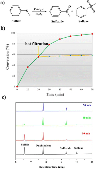
It is well known that sulfones and sulfoxides have a wide variety of applications in bioresearch, medicinal chemistry and chemical industry. Therefore, seeking for excellent catalysts to complete the selective oxidation of sulfides to their homologous sulfones and sulfoxides is a meaningful and significant topic in the catalyst research. POMs and their derivatives are known to serve on oxidation catalysts; herein, the selective oxidation of multifarious sulfides to their homologous sulfones was investigated.First, MPS was selected as the standard catalytic reaction to assess the catalytic oxidation activities in the presence of 1 and 2. To carry on the catalytic oxidation system, MPS (0.25 mmol), oxidant H2O2 (0.4 mmol), internal standard naphthalene (0.25 mmol) and the catalysts (2 μmol) were mixed in methanol (0.5 mL) at 45 °C, and the catalytic performance was detected by gas chromatography (GC). As expected, compounds 1 and 2 exhibit good catalytic capacities, and the substrate MPS can be almost oxidized to corresponding methyl phenyl sulfoxide (MPSO). Just as in Fig. 6b, compound 1 can oxidize 98.2% of MPS into MPSO with 94.6% selectivity. In addition, the recorded progress of the catalytic oxidation of MPS in the presence of 1 through GC signals is displayed in Fig. 6c, which can deduce that MPS was almost catalyzed to corresponding MPSO. Table S2† indicates that compounds 1 and 2 were also comparable to those of the reported POM-based catalysts for MPS oxidation. We also studied the catalytic oxidation of MPS using other catalysts (Table S3†). The catalytic results indicated that both catalysts {BW12} and Cu site together can catalyze oxidation of MPS, which can also explain that compound 1 shows a little higher catalytic performance than that of compound 2. The catalytic reaction kinetics of MPS was also studied. Just as in Fig. S23,† a plot of the catalytic reaction time versus ln(Ct/C0) exhibits a linear correlation, which indicates that the catalytic oxidation of MPS is the first-order reaction (k1 = 0.06019 min−1, R2 = 0.99027 and k2 = 0.04607 min−1, R2 = 0.99027) (Fig. S23†). After a reaction time of 20 min, catalyst 1 was removed via a hot filtration experiment, and the oxidative conversion of MPS increases a little as time goes on (Fig. 6b and S22†). The above-mentioned results suggest that this catalytic system is heterogeneous. Therefore, we further studied the recyclability and stability of 1. The conversion and selectivity of MPS remained almost constant in the following repeated cycles under similar conditions (Fig. S24†). The cyclic catalyst was separated by simple filtration, washed with methanol, dried and reused for the next cycle. Furthermore, in this report, the comparison of IR spectra and PXRD patterns remaining constant before and after catalytic reactions can also conclude that the catalytic system is heterogeneous (Fig. S25†).
Then, encouraged by the catalytic performances of compounds 1 and 2 for the oxidation of MPS in methanol, a sequence of parallel experiments were further performed under optimal conditions to investigate the catalytic universality of 1 and 2. Gratifyingly, similar and excellent catalytic performances toward various sulfides with different electronic and steric effects can be observed from Table 1. The catalytic results of compounds 1 and 2 did not obviously decrease no matter introducing the electron donor (such as methyl or methoxy group) or acceptor units (such as chlorine or fluorine group) into MPS. Additionally, dibenzyl sulfide and diphenyl sulfide with large steric hindrance can also be efficiently oxidized to corresponding sulfones. These catalytic reactions further indicated that compounds 1 and 2 possessed catalytic universality in the oxidation of sulfides.
| Ca | Substrates | Products | Con (%) | Selb (%) |
|---|---|---|---|---|
| a Reaction conditions: sulfide (0.25 mmol), catalysts (0.8 mol%), H2O2 (4 mmol), methanol (0.5 mL). b Selectivity to sulfoxides. | ||||
| 1/2 |

|

|
98.2/95.6 | 94.6/93.5 |
| 1/2 |

|

|
96.8/94.5 | 94.2/93.8 |
| 1/2 |

|

|
96.5/94.1 | 92.8/91.1 |
| 1/2 |

|

|
95.6/92.4 | 91.4/91.2 |
| 1/2 |

|

|
95.3/91.7 | 90.1/90.5 |
| 1/2 |

|

|
78.9/75.8 | 89.4/85.9 |
| 1/2 |

|

|
92.6/91.8 | 88.5/86.4 |
| 1/2 |

|

|
90.9/87.9 | 87.1/84.7 |
In the light of previous investigations, we know that the peroxo-metal group derived from POMs with the oxidizing agent H2O2 is the actual catalyst. Therefore, the possible mechanism for the catalytic oxidation of MPS was proposed (Fig. 7a). To testify the existence of the peroxo species, we examine the UV-Vis spectra of the dimethyl sulfoxide (DMSO) solution of compounds 1 or 2 before and after the addition of the oxidizing agent H2O2 (Fig. 7b and c). Obvious red shifts were observed after compounds were mixed H2O2 in the ultraviolet region (290 nm → 297 nm 1, 294 nm → 300 nm 2), which can indicate the formation of peroxo species.
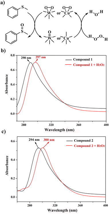 | ||
| Fig. 7 (a) Proposed mechanism of the selective oxidation of MPS; (b and c) UV-vis spectra of compound 1 and 2 in DMSO with H2O2 in the UV region. | ||
4. Conclusions
In summary, we have designed and isolated two POM-based metal–organic frameworks via a simple one-step solvothermal reaction by adjusting the pH value and fully characterized them. Both compounds exhibit charming 3D framework structures, in particular the Cu–organic framework of 2 shows the fascinating shape of vase structures. Compounds 1 and 2 displayed good specific capacitance of 214.59 F g−1 and 189.17 F g−1 at 0.48 A g−1, respectively, and capacitance retention rates of compounds 1 and 2 can still remain at 91.55% and 90.2% after 1000 cycles. In addition, the two compounds can efficiently and selectively convert MPS into their corresponding MPSO. These results represent a hopeful strategy for investigating POM-based metal–organic complexes as supercapacitors and catalysts for selective oxidation of sulfides.Conflicts of interest
There are no conflicts to declare.Acknowledgements
This work is financially supported by the Major Research Program of High Education of Henan Province (21B150017; 21B150019); the Joint Program for Fostering Talents of National Natural Science Foundation of China and Henan Province (U1304202), State Scholarship Fund, Henan Province Science and Technology Project (222300420523) and The Scientific Research Innovation Team of Xuchang University (2022CXTD001).References
- D. W. Xiao, Q. Y. Dou, L. Zhang, Y. L. Ma, S. Q. Shi, S. L. Lei, H. Y. Yu and X. B. Yan, Optimization of organic/water hybrid electrolytes for high-rate carbon-based supercapacitor, Adv. Funct. Mater., 2019, 42, 1904136 CrossRef.
- S. Zheng, H. Xue and H. Pang, Supercapacitors based on metal coordination materials, Coord. Chem. Rev., 2017, 373, 2–21 CrossRef.
- M. Salanne, B. Rotenberg, K. Naoi, K. Kaneko, P. L. Taberna, C. P. Grey, B. Dunn and P. Simon, Efficient storage mechanisms for building better supercapacitors, Nat. Energy, 2016, 1, 16070–16079 CrossRef CAS.
- Z. Y. Liu, Z. P. Chen, C. Wang, H. I. Wang, M. Wuttke, X. Y. Wang, M. Bonn, L. F. Chi, A. Narita and K. Müllen, Bottom-Up, on surface-synthesized armchair graphene nanoribbons for ultra-high power micro-supercapacitors, J. Am. Chem. Soc., 2020, 142, 17881–17886 CrossRef CAS PubMed.
- Y. D. Wang, C. Shen, L. Y. Niu, R. Z. Li, H. T. Guo, Y. X. Shi, C. Li, X. J. Liu and Y. Y. Gong, Hydrothermal synthesis of CuCo2O4/CuO nanowire arrays and RGO/Fe2O3 composites for high-performance aqueous asymmetric supercapacitors, J. Mater. Chem. A, 2016, 4, 9977–9985 RSC.
- A. Yamada and J. B. Goodenough, Keggin-Type Heteropolyacids as Electrode Materials for Electrochemical Supercapacitors, J. Electrochem. Soc., 1998, 145, 737–743 CrossRef CAS.
- S. Herrmann, N. Aydemir, F. Nägele, D. Fantauzzi, T. Jacob, J. Travas-Sejdic and C. Streb, Enhanced capacitive energy storage in polyoxometalate-doped polypyrrole, Adv. Funct. Mater., 2017, 27, 1700881 CrossRef.
- J. J. Lin, S. Yan, X. J. Zhang, Y. R. Liu, J. Lian, H. L. Lin, W. Wei, D. L. Lu and S. Han, Facile preparation of holey anderson-type polyoxometalate polyaniline graphene nanocomposites for supercapacitors, Nano, 2019, 14, 1950049 CrossRef CAS.
- J. Suárez-Guevara, V. Ruiz and P. Gomez-Romero, Hybrid Energy Storage: High voltage aqueous supercapacitors based on activated carbon–phosphotungstate hybrid materials, J. Mater. Chem. A, 2014, 2, 1014–1021 RSC.
- A. A. Vannathan, T. Kella, D. Shee and S. S. Mal, One-Pot Synthesis of Polyoxometalate decorated polyindole for energy storage supercapacitors, ACS Omega, 2021, 6, 11199–11208 CrossRef CAS.
- P. P. Shi, L. Li, L. Hua, Q. Q. Qian, P. F. Wang, J. Y. Zhou, G. Z. Sun and W. Huang, Design of amorphous manganese oxide@ multiwalled carbon nanotube fiber for robust solid-state supercapacitor, ACS Nano, 2017, 11, 444–452 CrossRef CAS PubMed.
- H. N. Wang, M. Zhang, A. M. Zhang, F. C. Shen, X. K. Wang, S. N. Sun, Y. J. Chen and Y. Q. Lan, Polyoxometalate-based metal–organic frameworks with conductive polypyrrole for supercapacitors, ACS Appl. Mater. Interfaces, 2018, 10, 32265–32270 CrossRef CAS PubMed.
- L. Yang, J. Lei, J. M. Fan, R. M. Yuan, M. S. Zheng, J. J. Chen and Q. F. Dong, The intrinsic charge carrier behaviors and applications of polyoxometalate clusters based materials, Adv. Mater., 2021, 33, 2005019 CrossRef CAS.
- J. Lei, X. X. Fan, T. Liu, P. Xu, Q. Hou, K. Li, R. M. Yuan, M. S. Zheng, Q. F. Dong and J. J. Chen, Single-dispersed polyoxometalate clusters embedded on multilayer graphene as a bifunctional electrocatalyst for efficient Li-S batteries, Nat. Commun., 2022, 13, 202 CrossRef CAS PubMed.
- Y. Hou, H. J. Pang, C. J. Gómez-García, H. Y. Ma, X. M. Wang and L. C. Tan, Polyoxometalate metal–organic frameworks: Keggin clusters encapsulated into silver-triazole nanocages and open frameworks with supercapacitor performance, Inorg. Chem., 2019, 8, 16028–16039 CrossRef.
- N. N. Du, L. G. Gong, L. Y. Fan, K. Yu, H. Luo, S. J. Pang, J. Q. Gao, Z. W. Zheng, J. H. Lv and B. B. Zhou, Nanocomposites containing Keggin anions anchored on pyrazine-based frameworks for use as supercapacitors and photocatalysts, ACS Appl. Nano Mater., 2019, 2, 3039–3049 CrossRef CAS.
- X. Wang, H. Li, J. F. Lin, C. Y. Wang and X. L. Wang, Capped Keggin type polyoxometalate-based inorganic–organic hybrids involving in situ ligand transformation as supercapacitors and efficient electrochemical sensors for detecting Cr(VI), Inorg. Chem., 2021, 60, 19287–19296 CrossRef CAS PubMed.
- G. N. Wang, T. T. Chen, C. J. Gómez-García, F. Zhang, M. Y. Zhang, H. Y. Ma, H. J. Pang, X. M. Wang and L. C. Tan, A high-capacity negative electrode for asymmetric supercapacitors based on a PMo12 coordination polymer with novel water-assisted proton channels, Small, 2020, 29, 2001626 CrossRef.
- M. R. Horn, A. Singh, S. Alomari, S. Goberna-Ferrón, R. BenagesVilau, N. Chodankar, N. Motta, K. Ostrikov, J. MacLeod, P. Sonar, P. Gomez-Romero and D. Dubal, Polyoxometalates (POMs): from electroactive clusters to energy materials, Energy Environ. Sci., 2021, 14, 1652–1700 RSC.
- R. T. Yang, A. J. Hernández-Maldonado and F. H. Yang, Desulfurization of transportation fuels with zeolites under ambient conditions, Science, 2003, 301, 79–81 CrossRef CAS PubMed.
- W. Zhao, C. Yang, Z. Cheng and Z. Zhang, A reusable catalytic system for sulfide oxidation and epoxidation of allylicalcohols in water catalyzed by poly (dimethyl diallyl) ammonium/polyoxometalate, Green Chem., 2016, 18, 995–998 RSC.
- T. Ishizuka, S. Ohkawa, H. Ochiai, M. Hashimoto, K. Ohkubo, H. Kotani, M. Sadakane, S. Fukuzumi and T. Kojima, A supramolecular photocatalyst composed of a polyoxometalate and a photosensitizing water-soluble porphyrin diacid for the oxidation of organic substrates in water, Green Chem., 2018, 20, 1975–1980 RSC.
- P. Mialane, C. Mellot-Draznieks, P. Gairola, M. Duguet, Y. Benseghir, O. Oms and A. Dolbecq, Heterogenisation of polyoxometalates and other metal-based complexes in metal–organic frameworks: from synthesis to characterisation and applications in catalysis, Chem. Soc. Rev., 2021, 50, 6152–6220 RSC.
- K. J. Liu, J. H. Deng, J. Yang, S.-F. Gong, Y.-W. Lin, J.-Y. He, Z. Cao and W.-M. He, Selective oxidation of (hetero)sulfides with molecular oxygen under clean conditions, Green Chem., 2020, 22, 433–438 RSC.
- M. Ahmadian and M. Anbia, Oxidative desulfurization of liquid fuels using polyoxometalate-based catalysts: a review, Energy Fuels, 2021, 35, 10347–10373 CrossRef CAS.
- J. Song, Y. Li, P. Cao, X. Jing, M. Faheem, Y. Matsuo, Y. Zhu, Y. Tian, X. Wang and G. Zhu, Synergic catalysts of polyoxometalate@cationic porous aromatic frameworks: reciprocal modulation of both capture and conversion materials, Adv. Mater., 2019, 31, 1902444 CrossRef CAS PubMed.
- H. Y. An, Y. J. Hou, S. Z. Chang, J. Zhang and Q. S. Zhu, Highly efficient oxidation of various thioethers catalyzed by organic ligand-modified polyoxomolybdates, Inorg. Chem. Front., 2020, 7, 169–176 RSC.
- Z. Chen, C. Liu, J. Liu, J. Li, S. Xi, X. Chi, H. Xu, I. H. Park, X. Peng, X. Li, W. Yu, X. Liu, L. Zhong, K. Leng, W. Huang, M. J. Koh and K. P. Loh, Cobalt single-atom-intercalated molybdenum disulfide for sulfide oxidation with exceptional chemoselectivity, Adv. Mater., 2020, 32, 1906437 CrossRef CAS PubMed.
- J. B. Yang, J. H. Pan, Y. H. Zhu, J. L. Wang, H. Mei and Y. Xu, Two 1D Anderson-Type polyoxometalate-based metal–organic complexes as bifunctional heterogeneous catalysts for CO2 photoreduction and sulfur oxidation, Inorg. Chem., 2022, 61, 11775–11786 CrossRef CAS PubMed.
- M. D. Han, Y. J. Niu, R. Wan, Q. F. Xu, J. K. Lu, P. T. Ma, C. Zhang, J. Y. Niu and J. P. Wang, A Crown-shaped Ru-substituted arsenotungstate for selective oxidation of sulfides with hydrogen peroxide, Chem. – Eur. J., 2018, 24, 11059–11066 CrossRef CAS PubMed.
- T. A. G. Duarte, S. M. G. Pires, I. C. M. S. Santos, M. M. Q. Simões, G. Neves, A. M. V. Cavaleirob and J. A. S. Cavaleiroa, A Mn(iii) polyoxotungstate in the oxidation of organosulfur compounds by H2O2 at room temperature: an environmentally safe catalytic approach, Catal. Sci. Technol., 2016, 6, 3271–3278 RSC.
- J. K. Lu, X. Y. Ma, V. Singh, Y. J. Zhang, P. T. Ma, C. Zhang, J. Y. Niu and J. P. Wang, An isotetramolybdate-supported rhenium carbonyl derivative: synthesis, characterization, and use as a catalyst for sulfoxidation, Dalton Trans., 2018, 47, 5279–5285 RSC.
- T. Y. Dang, R. H. Li, H. R. Tian, Q. Wang, Y. Lu and S. X. Liu, Tandem-like vanadium cluster chains in a polyoxovanadate-based metal–organic framework for efficient catalytic oxidation of sulfides, Inorg. Chem. Front., 2021, 8, 4367–4375 RSC.
- Y. H. Chen, S. Z. Chang, H. Y. An, Y. Q. Li, Q. S. Zhu, H. Y. Luo and Y. H. Huang, Two Polymorphic polyoxometalate-based metal–organic frameworks for the efficient synthesis of functionalized sulfoxides and detoxification of mustard gas simulants, ACS Sustainable Chem. Eng., 2021, 9, 15683–15693 CrossRef CAS.
- Y. H. Chen, H. Y. An, S. Z. Chang, Y. Q. Li, Q. S. Zhu, H. Y. Luo and Y. H. Huang, A POM-based porous supramolecular framework for efficient sulfide–sulfoxide transformations with a low molar O/S ratio, Inorg. Chem. Front., 2022, 9, 3282–3294 RSC.
- C. R. Deltcheff, M. Fournier and R. Franck, Vibrational investigations of polyoxometalates. Evidence for anion-anion interactions in molybdenum(VI) and tungsten(VI) compounds related to the Keggin structure, Inorg. Chem., 1983, 22, 207–216 CrossRef.
- S. Soni, K. Pareek, D. K. Jangid and R. Rohan, Carbon Clot-MnO2 nanotube composite for flexible supercapacitor, Energy Storage, 2020, 2, e189 CrossRef CAS.
- W. L. Zhou, J. Peng, Z. Y. Zhang, Z. Y. Shi, S. U. Khan and H. S. Liu, Assembly of hybrids based on polyoxotungstates and Cotris(imidazolyl) complexes with bifunctional electrocatalytic activities, RSC Adv., 2015, 5, 35753–35759 RSC.
- T. Brezesinski, J. Wang, J. Polleux, B. Dunn and S. H. Tolbert, Templated nanocrystal-based porous TiO2 films for next-generation electrochemical capacitors, J. Am. Chem. Soc., 2009, 131, 1802–1809 CrossRef CAS PubMed.
- J. Wang, J. Polleux, J. Lim and B. Dunn, Pseudocapacitive contributions to electrochemical energy storage in TiO2 (anatase) nanoparticles, J. Phys. Chem. C, 2007, 111, 14925–14931 CrossRef CAS.
- H. Li, L. J. Wu, S. G. Zhang, C. Yao, C. Y. Chao, H. W. Yue and H. H. Fan, Facile synthesis of mesoporous one-dimensional Fe2O3 nanowires as anode for lithium ion batteries, J. Alloys Compd., 2020, 832, 155008 CrossRef CAS.
Footnote |
| † Electronic supplementary information (ESI) available: IR spectra, UV–Vis diffuse reflective spectra, TG plots, PXRD figures, XPS, SEM, EDS for 1 and 2; crystal structure figures of 1 and 2; plots of the anodic and cathodic peaks current vs. scan rates; catalytic oxidation of MPS oxidation figures and table for 1 and 2; crystal data and structure refinement for 1 and 2; selected distances and angles for 1 and 2. CCDC 2205037 and 2205038. For ESI and crystallographic data in CIF or other electronic format see DOI: https://doi.org/10.1039/d2qi01922a |
| This journal is © the Partner Organisations 2023 |

