 Open Access Article
Creative Commons Attribution 3.0 Unported Licence
Magnetically separable triazine-based Cu(II)–vitamin B5 complex in nitromethane toward efficient heterogeneous cyanation reaction of aryl halides†
Farzaneh Karimi‡
,
Masoumeh Jadidi Nejad‡ ,
Arefe Salamatmanesh and
Akbar Heydari*
Chemistry Department, Tarbiat Modares University, P.O. Box 14155-4838, Tehran, Iran. E-mail: heydar_a@modares.ac.ir; Fax: +98-21-82883455; Tel: +98-21-82883444
First published on 5th January 2023
Abstract
In the current study, a highly efficient heterogeneous copper catalyst has been developed by supporting copper acetate on a magnetically separable triazine–vitamin B5 system. After the successful characterization of the prepared nanoparticles by various techniques such as FT-IR, FE-SEM, EDX/MAP, XRD, TEM, TGA, VSM, and ICP-OES, the catalytic efficiency of them were evaluated in the cyanation reaction of aryl halides in the presence of nitromethane as a non-toxic and cost-effective cyanation source. The cyanation products were obtained in desirable yields. Notably, the magnetic nanocatalyst can be easily recovered and reused at least five times without a significant decrease in its performance.
1 Introduction
Aromatic nitriles are an important class of versatile scaffolds present in natural compounds and many synthetic organic products, such as dyes, pharmaceuticals, agrochemicals, and herbicides.1 They can also be transformed into a variety of organic compounds such as imines, aldehydes, amines, amides, esters, carboxylic acids, and tetrazoles.2 In recent decades, novel methodologies have been developed for the introduction of a nitrile functional group into an aromatic framework. The diazotization of anilines followed by the Sandmeyer reaction3 and also the Rosenmund–von Braun reaction4 have been known as classic synthetic methods toward aryl nitriles. Since then, a series of transition metal-catalyzed protocols have been reported for the cyanation reactions by using diverse cyano sources such as KCN,5 NaCN,6 Zn(CN)2,7 CuCN,8 and TMSCN.9 Nevertheless, most of them are confronted with significant drawbacks including the use of toxic metal cyanides in stoichiometric amounts and the requirement of harsh reaction conditions. To overcome this problems, several less-toxic metal-free cyanide sources including malononitrile,10 butyronitrile,11 acetonitrile,12 benzyl cyanide,13 AIBN,14 etc. have been disclosed. Furthermore, some other organic compounds, which can generate cyano groups in situ have been employed as indirect cyanation sources. Explored examples of such cyanation reagents include NH4I/DMF,15 NH4HCO3/DMSO,16 NH4HCO3/DMF,17 t-BuNC,18 etc. Recently, nitromethane has also been introduced as a potentially valuable indirect organic cyano source for the cyanation of organic scaffolds, because of its chemical stability, and low-cost commercial availability. Nevertheless, there are very few reports on the use of nitromethane as a cyanation reagent in the field of metal-catalyzed aromatic CCN bond formation. So, it is still demanding to make attempts in this direction.19Over the recent past decades, various transition metals, such as Pd,20 Co,21 Ni,22 Cu,10 Rh23 and Zn24 have been utilized to catalyze cyanation reactions of aryls and aryl halides using different cyanation sources. Among them, the use of Cu as a readily available and inexpensive transition metal can be desirable.17,19 However, most of these reported metal-catalyzed cyanation reactions have adopted a homogeneous approach, which suffer from serious limitations including high expenses, problematic separation (in some cases non-separable), and non-reusability of metal catalysts. To meet these restrictions as well as minimize possible pollution caused by toxic metal discharge in some homogeneous protocols, a wide range of heterogeneous metal-incorporating catalytic systems have been developed for cyanation transformations.25 Magnetic nanoparticles have been well known as one of the most promising heterogeneous nanostructures, which have unique physicochemical features in addition to being easily recoverable and reusable.26
Until now, various reports have been presented about the use of ligands in the cyanidation reaction, and by examining the used ligands and the importance of ligands containing nitrogen and oxygen in binding to various metals and forming stable complexes,27–30,19a we chose vitamin B5 as a suitable ligand for this reaction.
To the best of our knowledge, no heterogeneous copper catalyst has been reported for the cyanation of aryl halides using nitromethane as an indirect organic nitrile source. In this work, we designed and synthesized a novel heterogeneous copper-incorporating nanocatalyst by loading copper acetate on a magnetically recyclable triazine–vitamin B5 system for the synthesis of aryl nitriles from aryl halide substrates in presence of nitromethane.
2 Experimental
2.1. General remarks
All required materials were purchased from Aldrich and Merck companies and were used without any further purification. The reaction was monitored by thin-layer chromatography. TLC was performed on glass plates incorporated with silica-gel 60 F-254. Infrared spectrums (IR) were determined by grade KBr on a Nicolet FT-IR 100 spectrometer. X-ray diffraction (XRD) data were obtained at room temperature by a Philips X-pert 1710. The size and morphology of the nanoparticles were determined by scanning electron microscopy (SEM) using a TESCAN MIRA III FE-SEM. Also, the elemental composition of the nanoparticles was studied by energy-dispersive X-ray (EDAX). Transmission electron microscopy (TEM) was performed using a Philips CM 120 at 120 kV. Thermal gravimetric analysis (TGA) was performed by a thermal analyzer with a heating rate of 10 °C min−1 in the range of 25–800 °C under the following air.2.2. Synthesis of TCT/B5
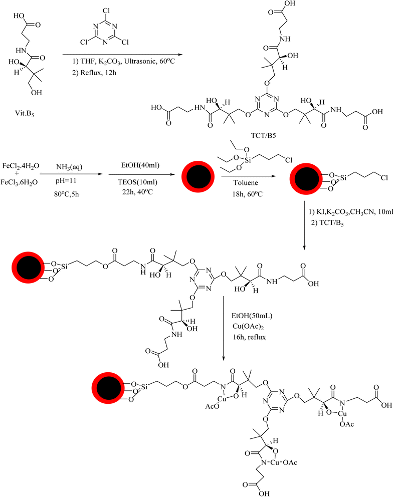
Cyanuric chloride (1 mmol or 0.18 g) was dissolved in 5 mL of anhydrous tetrahydrofuran (THF). The resulting solution was then slowly added to a solution of vitamin B5 in anhydrous THF (5 mL) and ultrasonicated at 60 °C. Potassium carbonate (1 mmol or 0.138 g) was added to the reaction mixture, and the solution was kept under the same conditions for 3 h and then stirred for 12 h at 70 °C. Finally, the reaction mixture was centrifuged, and the product was separated, washed with anhydrous THF, and dried in a vacuum oven at 70 °C.2.3. Synthesis of Fe3O4@SiO2
A mixture of FeCl3·6H2O (5 mmol or 1.35 g) and FeCl2·4H2O (2.5 mmol or 0.5 g) in 50 mL deionized water was ultrasonicated for 10 min to be completely dispersed. While the solution was being stirred at room temperature, 20 mL of ammonia solution (37%) was added dropwise until reaching pH = 11. The solution was then stirred under a nitrogen atmosphere at 80 °C for 5 h. Thereafter, the solution was cooled down to 40 °C, 40 mL of ethanol was added, and the reaction mixture was stirred for 30 min. Tetraethyl orthosilicate (10 mL) was gradually added to the reaction mixture and it was then placed under a nitrogen atmosphere at 40 °C for 22 h. The Fe3O4@SiO2 product was separated by applying an external magnetic field, washed several times with water and ethanol, and dried in a vacuum oven at 80 °C.2.4. Synthesis of Fe3O4@SiO2–TCT/B5
Anhydrous toluene (50 mL) was added to 0.2 g Fe3O4@SiO2, and the solution was ultrasonicated for 15 min to be completely dispersed. Then, (3-chloropropyl)trimethoxysilane (10 mL) was added to the dispersion, and the mixture was stirred at 60 °C for 18 h under a nitrogen atmosphere. The nanoparticles were separated by applying an external magnetic field, washed several times with anhydrous toluene, and dried in a vacuum oven at 80 °C. First, potassium iodide (2 mmol or 0.332 g), then potassium carbonate (2 mmol or 0.276 g), and, finally, TA/B5 (0.2 g) were added to Fe3O4@SiO2–Cl (0.2 g) dispersed in 10 mL acetonitrile, and the mixture was refluxed for 12 h. The nanoparticles were then separated by applying an external magnetic field, washed several times with water and ethanol, and dried in a vacuum oven at 80 °C.2.5. Synthesis of Fe3O4@SiO2–TCT/B5–Cu(II)
Fe3O4@SiO2–TCT/B5 (0.2 g) was dispersed in 50 mL ethanol through 15 min ultrasonication. Next, 1 mmol of copper(II) acetate monohydrate dissolved in ethanol was added dropwise to the dispersion. The resulting mixture was then refluxed for 16 h. The nanoparticles are separated by applying an external electric field, washed several times with ethanol, and dried in a vacuum oven at 60 °C.2.6. Procedure route for the synthesis of aryl cyanides
First, 4-iodoanisole (1 mmol or 0.234 g), nitromethane (3 mmol or 0.183 g), potassium carbonate (1 mmol or 0.138 g), and the catalyst (30 mg) were weighed and poured into a glass tube. Then, 3 mL dimethyl sulfoxide (solvent) was added and the mixture was stirred at 100 °C for 12 h. Thin-layer chromatography was used to monitor the progress of the reaction. Upon the completion of the reaction, the reaction mixture was cooled down to room temperature, and the catalyst was removed by a magnet. The reaction mixture was then extracted by water and ethyl acetate. After any remaining water droplets were removed from the organic phase by using anhydrous sodium sulfate, the solvent was evaporated under a vacuum. Finally, the purification process was carried out using silica gel plates and ethyl acetate![[thin space (1/6-em)]](https://www.rsc.org/images/entities/char_2009.gif) :
:![[thin space (1/6-em)]](https://www.rsc.org/images/entities/char_2009.gif) hexane (1
hexane (1![[thin space (1/6-em)]](https://www.rsc.org/images/entities/char_2009.gif) :
:![[thin space (1/6-em)]](https://www.rsc.org/images/entities/char_2009.gif) 9) solvent.
9) solvent.
3 Results and discussion
3.1. Catalyst preparation
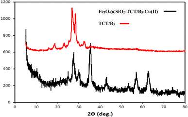
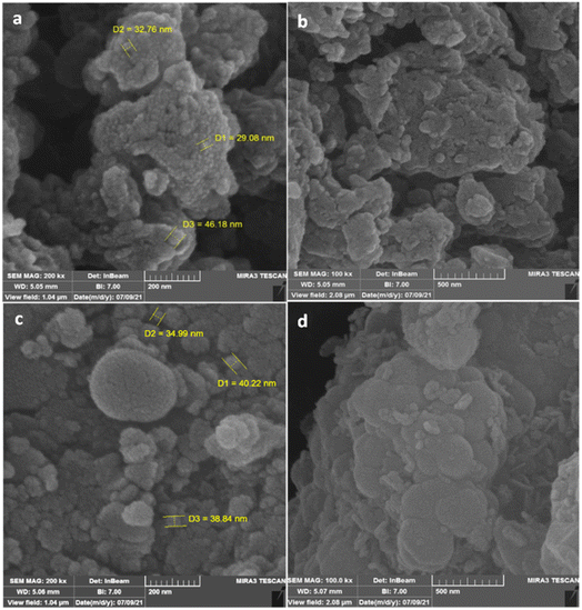
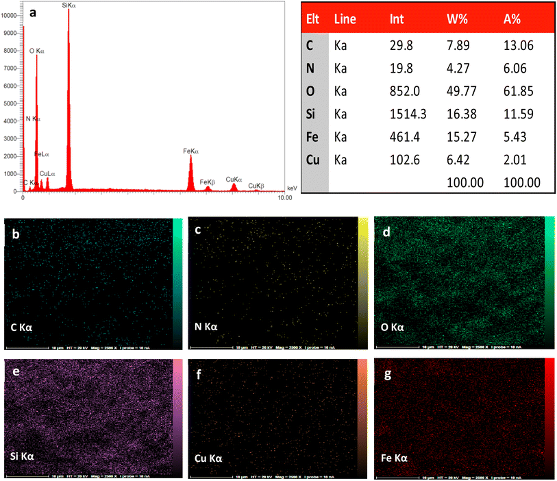
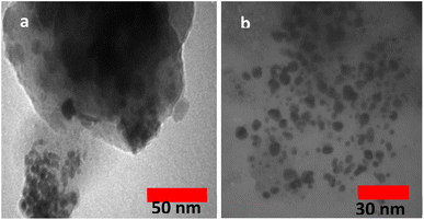
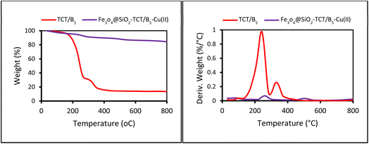
The preparation process of the proposed Fe3O4@SiO2–TCT/B5–Cu(II) nanocatalyst is illustrated in Scheme 1 as explained in the experimental section. Then to elucidate the structure of the prepared nanocatalyst, several analyses including FT-IR, XRD, SEM, TEM, EDX, TGA, and ICP were carried out.3.2. Catalyst characterization
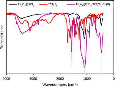
![[double bond, length as m-dash]](https://www.rsc.org/images/entities/char_e001.gif) N triazine ring, C–N, Si–O–Si and Fe–O bonds, indicating the successful attachment of TCT/B5 to the support. In addition, due to the coordination of some ligand groups with Cu(II) species, the intensity of some TCT/B5 peaks in the final catalyst has decreased.
N triazine ring, C–N, Si–O–Si and Fe–O bonds, indicating the successful attachment of TCT/B5 to the support. In addition, due to the coordination of some ligand groups with Cu(II) species, the intensity of some TCT/B5 peaks in the final catalyst has decreased.
3.3. Application of Fe3O4@SiO2–TCT/B5–Cu(II) catalyst in cyanation reaction
After characterization of the Fe3O4@SiO2–TCT/B5–Cu(II) catalyst, we studied its catalytic performance in the cyanation reaction of aryl halides using CH3NO2 as the cyanide resource (Scheme 2). In order to optimize the reaction conditions, we selected the cyanation of 4-iodoanisole with CH3NO2 as the model reaction (Table 1). First, the cyanation reaction was evaluated in the absence of a catalyst (entry 1), no product was obtained under this condition, confirming the need for a catalyst to afford the desired product. The reaction was also tested in the presence of Fe3O4@SiO2–TCT/B5 as a catalyst and no product was detected, indicating the necessity of copper for the formation an ideal product. The impacts of solvent, base, temperature, and amount of catalyst were studied to improve the reaction yield. To investigate the role of solvent in the cyanation reaction, a variety of solvents were applied in the reaction (entries 4–9). DMSO was chosen as the best solvent. Comparison between different bases used (entries 10–13), exhibited that K2CO3 has the best efficiency to form the cyanated product. Based on the catalyst loading study, various amounts of catalyst were tested in this reaction. The amount of 30 mg was found to be the best value of catalyst for high conversion under the reaction conditions. The model reaction in presence of lower values of the catalyst resulted in a decrease in the yield of the cyanation product (entries 14 and 15). Decreasing the reaction temperature to 90 °C brought down the yield to 81% (entry 18). By increasing the temperature to 110 °C (entry 17), no change in the yield of the product was observed. The cyanation reaction was carried out in the presence of copper on substrates Fe3O4 and Fe3O4@SiO2. These substrates are free of vitamin B5 to investigate the importance of the ligand in this reaction. According to the results, the importance of vitamin B5 in the prepared composite is concluded. The presence of vitamin B5 in the structure of catalyst is essential and enhances efficiency (entries 20 and 21).| Entry | Catalyst | Catalyst (mg) | Base | Solvent | Temp. (°C) | Yieldb (%) |
|---|---|---|---|---|---|---|
| a Reaction conditions: 4-iodoanisole (1 mmol or 0.234 g), nitromethane (3 mmol or 0.183 g), base (1 mmol), and catalyst (30 mg, 0.3 mol%), 12 h, 100 °C.b Isolated yield.c K2CO3 (2 mmol). | ||||||
| 1 | — | — | K2CO3 | DMSO | 100 | 0 |
| 2 | Cu(OAc)2 | 10 mol% | K2CO3 | DMSO | 100 | 38 |
| 3 | Fe3O4@SiO2–TCT/B5 | 30 | K2CO3 | DMSO | 100 | 0 |
| 4 | Fe3O4@SiO2–TCT/B5–Cu(II) | 30 | K2CO3 | DMSO | 100 | 94 |
| 5 | Fe3O4@SiO2–TCT/B5–Cu(II) | 30 | K2CO3 | K2CO3/glycerol (1![[thin space (1/6-em)]](https://www.rsc.org/images/entities/char_2009.gif) : :![[thin space (1/6-em)]](https://www.rsc.org/images/entities/char_2009.gif) 5) 5) |
100 | 10 |
| 6 | Fe3O4@SiO2–TCT/B5–Cu(II) | 30 | K2CO3 | CH3OH | 100 | 70 |
| 7 | Fe3O4@SiO2–TCT/B5–Cu(II) | 30 | K2CO3 | Toluene | 100 | 65 |
| 8 | Fe3O4@SiO2–TCT/B5–Cu(II) | 30 | K2CO3 | DMF | 100 | 85 |
| 9 | Fe3O4@SiO2–TCT/B5–Cu(II) | 30 | K2CO3 | CH3CN | 100 | 76 |
| 10 | Fe3O4@SiO2–TCT/B5–Cu(II) | 30 | NaHCO3 | DMSO | 100 | 51 |
| 11 | Fe3O4@SiO2–TCT/B5–Cu(II) | 30 | NaOH | DMSO | 100 | 82 |
| 12 | Fe3O4@SiO2–TCT/B5–Cu(II) | 30 | (CH3)2HN | DMSO | 100 | 59 |
| 13 | Fe3O4@SiO2–TCT/B5–Cu(II) | 30 | DABCO | DMSO | 100 | 68 |
| 14 | Fe3O4@SiO2–TCT/B5–Cu(II) | 20 | K2CO3 | DMSO | 100 | 84 |
| 15 | Fe3O4@SiO2–TCT/B5–Cu(II) | 10 | K2CO3 | DMSO | 100 | 71 |
| 16 | Fe3O4@SiO2–TCT/B5–Cu(II) | 40 | K2CO3 | DMSO | 100 | 94 |
| 17 | Fe3O4@SiO2–TCT/B5–Cu(II) | 30 | K2CO3 | DMSO | 110 | 94 |
| 18 | Fe3O4@SiO2–TCT/B5–Cu(II) | 30 | K2CO3 | DMSO | 90 | 81 |
| 19 | Fe3O4@SiO2–TCT/B5–Cu(II) | 30 | K2CO3 | DMSO | 100 | 95c |
| 20 | Fe3O4/Cu(II) | 30 | K2CO3 | DMSO | 100 | 33 |
| 21 | Fe3O4@SiO2–Cu(II) | 30 | K2CO3 | DMSO | 100 | 39 |
In order to evaluate the role of substituent groups, various aryl halides bearing both electron-rich and electron-poor groups were tested in this reaction (Table 2). Under the optimum reaction conditions, aryl iodides and bromides containing various substituents smoothly underwent the cyanation reaction to generate the corresponding benzonitriles in good to excellent yields. Aryl iodides provided higher reaction efficiency than aryl bromides due to the weakness of the C–I bond compared to C–Br. As shown in Table 2, O-substituted aryl halides (2f, 2k and 2l) gave lower yields compared to P-substitutes due to the hindrance effect.
| Entry | Substrate | Product | Yieldb (%) |
|---|---|---|---|
| a Reaction conditions: 4-iodoanisole (1 mmol or 0.234 g), nitromethane (3 mmol or 0.183 g), potassium carbonate (1 mmol or 0.138 g), and the catalyst (30 mg), 12 h, 100 °C.b Isolated yield. | |||
| 1 |  |
 |
X = I, 61 |
| X = Br, 45 | |||
| 2 |  |
 |
X = I, 80 |
| X = Br, 73 | |||
| 3 |  |
 |
67 |
| 4 |  |
 |
63 |
| 5 |  |
 |
X = I, 86 |
| X = Br, 78 | |||
| 6 |  |
 |
87 |
| 7 |  |
 |
43 |
| 8 |  |
 |
X = I, 78 |
| X = Br, 70 | |||
| 9 |  |
 |
X = I, 94 |
| X = Br, 88 | |||
The catalyst efficiency of Fe3O4@SiO2–TCT/B5–Cu(II) and effectiveness of the present approach were compared with the previous researches. As shown in Table 3, it benefits from the use of copper as an inexpensive and readily available transition metal along with a copper-based heterogeneous catalyst, which can be easily separated from the reaction mixture. As an important and considerable advantage of this approach, it can be mentioned the use of nitromethane as an inexpensive, available, non-metallic CN source with low toxicity, which is highly efficient for producing desirable products in the presence of the Fe3O4@SiO2–TCT/B5–Cu(II) catalyst.
| Entry | Catalyst | Condition | Yielda (%) | Recyclability (run) | Reference |
|---|---|---|---|---|---|
| a Isolated yield. | |||||
| 1 | γ-Fe2O3–Pd–NHC–n-butyl-SO3Na | Aryl halide (1 mmol), K4[Fe(CN)6]·3H2O (1.2 mmol), Et3N (4 mmol), H2O (6 mL), catalyst (0.2 mol%) | 94 | 6 | 31 |
| 2 | CuI/Pd(II)–AOFs | Aryl halide (10.0 mmol), potassium ferrocyanide (4.0 mmol), Cu(I)Pd(II)-AOFs (6 mol%), Na2CO3(10.0 mmol), DMAC, reflux | 98 | 4 | 32 |
| 3 | Fe3O4@PMDP/Pd | Aryl halide (1.0 mmol), K4[Fe(CN)6] (0.17 mmol), Fe3O4@PMDP/Pd (1.5 mol%), Na2CO3 (1.5 mmol), DMF(3 mL), 120 °C | 95 | 8 | 33 |
| 4 | Pd NPs@β-CD | Aryl halide (1.5 mmol), potassium ferrocyanide (0.2 mmol), Na2CO3(1.8 mmol), catalyst (0.05 mol%), DMF, 120 °C | 95 | 8 | 34 |
| 5 | Ni(acac)2 (5 mol%), AlCl3 (10 mol%), bpy (30 mol%) | Aryl halide (0.2 mmol), Ni(acac)2 (5 mol%), AlCl3 (10 mol%), Bpy (30 mol%), ZnO(1.0 equiv.), HCONH2(1.0 mL), 1,2-DME (1.5 mL), 145 °C | 90 | — | 35 |
| 6 | CuF2 | Aryl halide (0.2 mmol), CO(NH2)2 (4 equiv.), CuF2 (20 mol%), Li2CO3 (3 equiv.), O2, DMSO, 150 °C | 87 | — | 36 |
| 7 | Fe3O4@SiO2–TCT/B5–Cu(II) | Aryl halide (1 mmol), CH3NO2 (3 mmol), K2CO3 (1 mmol), catalyst (30 mg), 100 °C | 5 | This work | |
3.4. Mechanism
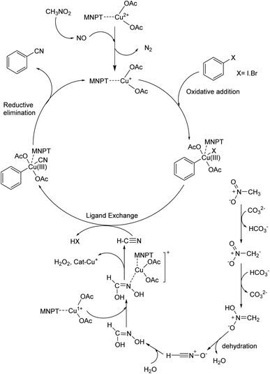
A possible mechanism for this reaction is proposed based on a similar previous report.19a,37,38 Thermochemical studies show that CH3NO2 can be decomposed into CO and NO at high temperatures. The released NO in the reaction medium interacts with Cu(II) in the catalyst and reduces Cu(II) to Cu(I). The 16-electron Cu(I) complex undergoes an oxidative addition reaction with aryl halide to form complex A. The 18-electron A complex performs ligand exchange in presence of HCN (generated from CH3NO2 using base) and produces B complex. Finally, complex B after a reductive elimination affords the cyanation product and the catalyst returns to the catalytic cycle (Scheme 3).3.5. Catalyst recyclability
We examined the recyclability and reusability of our catalyst in the cyanation reaction of 4-ome-iodobenzene in presence of CH3NO2 under the optimized conditions. The recyclability of the catalyst was evaluated for 5 consecutive runs. After each run of the reaction, catalyst was isolated by an external magnet, washed with EtOH and applied for the next run. As shown in Fig. 7, the catalytic activity has not changed significantly after 5 runs. The recycled catalyst in the 5th run was studied with SEM, XRD, and ICP analyses to investigate the catalyst stability under reaction conditions. The XRD pattern and SEM image have exhibited no significant difference with fresh catalyst. ICP analysis provided the Cu content of the recovered nanocatalyst after 5th run (0.65 mmol g−1) which did not show a significant decrease compared to that of the original catalyst.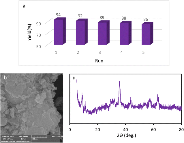 | ||
| Fig. 7 Recycling of the Fe3O4@SiO2–TCT/B5–Cu(II) nanocatalyst (a), SEM image (b) and XRD pattern (c) of the recovered Fe3O4@SiO2–TCT/B5–Cu(II) nanocatalyst. | ||
4 Conclusion
In conclusion, a novel and efficient catalytic approach for the synthesis of aryl nitriles in presence of Fe3O4@SiO2–TCT/B5–Cu(II) nanocatalyst and nitromethane as a non-toxic, inexpensive and readily available cyanating source has been developed. The aryl nitriles were obtained in moderate to good yields. The prepared heterogeneous nanocatalyst can be readily separated from the reaction mixture by magnetic filtration and recovered for at least five cycles without a significant loss of its activity.Ethical statement
This research does not involve human participants and/or animals.Data availability
The data that supports the findings of this study are available in the ESI† of this article.Author contributions
Conceptualization: Farzaneh Karimi, Masoumeh Jadidi Nejad; methodology: Farzaneh Karimi, Masoumeh Jadidi Nejad; formal analysis and investigation: Farzaneh Karimi and Masoumeh Jadidi Nejad; writing-original draft preparation: Masoumeh Jadidi Nejad, Arefe Salamatmanesh; writing-review and editing: Arefe Salamatmanesh, Masoumeh Jadidi Nejad; funding acquisition: Akbar Heydari; resources: Akbar Heydari; supervision: Akbar Heydari.Conflicts of interest
There are no conflicts of interest to declare.Acknowledgements
We are grateful to Tarbiat Modares University for financial support of this work.References
- (a) J. Magano and J. R. Dunetz, Chem. Rev., 2011, 111, 2177–2250 CrossRef CAS; (b) B. Patel, C. R. Firkin, E. W. Snape, S. L. Jenkin, D. Brown, J. G. K. Chaffey, P. A. Hopes, C. D. Reens, M. Butters and J. D. Moseley, Org. Process Res. Dev., 2012, 16, 447–460 CrossRef CAS; (c) A. Zanka, M. Nishiwaki, Y. Morinaga and T. Inoue, Org. Process Res. Dev., 1998, 2, 230–237 CrossRef CAS.
- (a) O. Kivrakidou, S. Bräse, F. Hülshorst and N. Griebenow, Org. Lett., 2004, 6, 1143–1146 CrossRef CAS; (b) R. C. Larock, Comprehensive organic transformations, Wiley Online Library, 1989 Search PubMed.
- T. Sandmeyer, Ber. Dtsch. Chem. Ges., 1884, 17, 2650–2653 CrossRef.
- (a) J. Von Braun and G. Manz, Justus. Liebigs Ann. Chem, 1931, 488, 111–126 CrossRef; (b) K. W. Rosenmund and E. Struck, Ber. Dtsch. Chem. Ges., 1919, 52, 1749–1756 CrossRef.
- C. Yang and J. M. Williams, Org. Lett., 2004, 6, 2837–2840 CrossRef CAS PubMed.
- B. A. Anderson, E. C. Bell, F. O. Ginah, N. K. Harn, L. M. Pagh and J. P. Wepsiec, J. Org. Chem., 1998, 63, 8224–8228 CrossRef CAS.
- F. Jin and P. N. Confalone, Tetrahedron Lett., 2000, 41, 3271–3273 CrossRef CAS.
- H.-Q. Do and O. Daugulis, Org. Lett., 2010, 12, 2517–2519 CrossRef CAS.
- X. Chen, X.-S. Hao, C. E. Goodhue and J.-Q. Yu, J. Am. Chem. Soc., 2006, 128, 6790–6791 CrossRef CAS.
- Z. Jiang, Q. Huang, S. Chen, L. Long and X. Zhou, Adv. Synth. Catal., 2012, 354, 589–592 CrossRef CAS.
- C. Qi, X. Hu and H. Jiang, Chem. Commun., 2017, 53, 7994–7997 RSC.
- Y. Zhu, M. Zhao, W. Lu, L. Li and Z. Shen, Org. Lett., 2015, 17, 2602–2605 CrossRef CAS PubMed.
- Q. Wen, J. Jin, B. Hu, P. Lu and Y. Wang, RSC Adv., 2012, 2, 6167–6169 RSC.
- H. Xu, P.-T. Liu, Y.-H. Li and F.-S. Han, Org. Lett., 2013, 15, 3354–3357 CrossRef CAS.
- J. Kim, H. Kim and S. Chang, Org. Lett., 2012, 14, 3924–3927 CrossRef CAS PubMed.
- X. Ren, J. Chen, F. Chen and J. Cheng, Chem. Commun., 2011, 47, 6725–6727 RSC.
- A. B. Pawar and S. Chang, Chem. Commun., 2014, 50, 448–450 RSC.
- S. Xu, X. Huang, X. Hong and B. Xu, Org. Lett., 2012, 14, 4614–4617 CrossRef CAS.
- (a) R. Saikia, S. Dey Baruah, R. C. Deka, A. J. Thakur and U. Bora, Eur. J. Org. Chem., 2019, 6211–6216 CrossRef CAS; (b) Y. Ogiwara, H. Morishita, M. Sasaki, H. Imai and N. Sakai, Chem. Lett., 2017, 46, 1736–1739 CrossRef CAS.
- M. Sundermeier, A. Zapf, S. Mutyala, W. Baumann, J. Sans, S. Weiss and M. Beller, Chem.–Eur. J., 2003, 9, 1828–1836 CrossRef CAS PubMed.
- D.-G. Yu, T. Gensch, F. de Azambuja, S. Vásquez-Céspedes and F. Glorius, J. Am. Chem. Soc., 2014, 136, 17722–17725 CrossRef CAS PubMed.
- X. Zhang, A. Xia, H. Chen and Y. Liu, Org. Lett., 2017, 19, 2118–2121 CrossRef CAS.
- A. B. Khemnar, D. N. Sawant and B. M. Bhanage, Tetrahedron Lett., 2013, 54, 2682–2684 CrossRef CAS.
- L. Zhao, Y. Dong, Q. Xia, J. Bai and Y. Li, J. Org. Chem., 2020, 85, 6471–6477 CrossRef CAS.
- (a) M. Nasrollahzadeh, S. M. Sajadi, A. Rostami-Vartooni and M. Khalaj, J. Colloid Interface Sci., 2015, 453, 237–243 CrossRef CAS PubMed; (b) A. Modak, J. Mondal and A. Bhaumik, Green Chem., 2012, 14, 2840–2855 RSC; (c) H. Yu, R. N. Richey, W. D. Miller, J. Xu and S. A. May, J. Org. Chem., 2011, 76, 665–668 CrossRef CAS; (d) M. Çalışkan and T. Baran, Int. J. Biol. Macromol., 2021, 174, 120–133 CrossRef.
- (a) H. Veisi, T. Tamoradi, A. Rashtiani, S. Hemmati and B. Karmakar, J. Ind. Eng. Chem., 2020, 90, 379–388 CrossRef CAS; (b) T. Baran, Carbohydr. Polym., 2020, 237, 116105 CrossRef CAS; (c) M. Jadidi Nejad and A. Heydari, Appl. Organomet. Chem., 2021, 35, e6368 CrossRef CAS; (d) A. Salamatmanesh and A. Heydari, Appl. Catal., A, 2021, 624, 118306 CrossRef CAS.
- H. Jiang, J. Jiang, H. Wei and C. Cai, Catal. Lett., 2013, 143, 1195–1199 CrossRef CAS.
- Y. Cai, H. Yuan, Q. Gao, L. Wu, L. Xue, N. Feng and Y. Sun, Catal. Lett., 2022, 1–17 Search PubMed.
- B. Tamami, M. Mohaghegh Nezhad, S. Ghasemi and F. Farjadian, Phosphorus, Sulfur Silicon Relat. Elem., 2016, 191, 123–128 CrossRef CAS.
- Y. Ogiwara, H. Morishita, M. Sasaki, H. Imai and N. Sakai, Chem. Lett., 2017, 46, 1736–1739 CrossRef CAS.
- F. O. Chahkamali, S. Sobhani and J. M. Sansano, Catal. Lett., 2021, 1–19 Search PubMed.
- Z.-C. Wu, Q. Yang, X. Ge, Y.-M. Ren, R.-C. Yang and T.-X. Tao, Catal. Lett., 2017, 147, 1333–1338 CrossRef.
- H. Veisi, S. Hemmati and P. Safarimehr, J. Catal., 2018, 365, 204–212 CrossRef CAS.
- T. Baran and M. Nasrollahzadeh, Inorg. Chem. Commun., 2020, 119, 108117 CrossRef CAS.
- L. Yang, Y.-T. Liu, Y. Park, S.-W. Park and S. Chang, ACS Catal., 2019, 9, 3360–3365 CrossRef CAS.
- K. Zheng, B. Liu, S. Chen and F. Chen, Tetrahedron Lett., 2013, 54, 5250–5252 CrossRef CAS.
- X. Li, X. Ren, H. Wu, W. Zhao, X. Tang and G. Huang, Chin. Chem. Lett., 2021, 32, 9–12 CrossRef CAS.
- M.-H. Shen, T.-B. Wan, X.-R. Huang, Y. Li, D.-H. Qian, H.-D. Xu and D. Xu, Chin. Chem. Lett., 2021, 32, 2297–2300 CrossRef CAS.
Footnotes |
| † Electronic supplementary information (ESI) available. See DOI: https://doi.org/10.1039/d2ra06104j |
| ‡ These authors contributed equally. |
| This journal is © The Royal Society of Chemistry 2023 |

