 Open Access Article
Future prospects and recent developments of polyvinylidene fluoride (PVDF) piezoelectric polymer; fabrication methods, structure, and electro-mechanical properties
Soha Mohammadpourfazeli†
 a,
Shabnam Arash†b,
Afshin Ansari†c,
Shengyuan Yang
 d,
Kaushik Mallick
 e and
Roohollah Bagherzadeh†
 *ad
*ad
aAdvanced Fibrous Materials LAB, Institute for Advanced Textile Materials and Technologies (ATMT), Amirkabir University of Technology (Tehran Polytechnic), Tehran, Iran. E-mail: bagherzadeh_r@aut.ac.ir
bDepartment of Biomechanics, University of Nebraska Omaha, USA
cMaterial Engineering Department, Imam Khomeini International University (IKIU), Iran
dState Key Laboratory for Modification of Chemical Fibers and Polymer Materials, College of Materials Science and Engineering, Donghua University, Shanghai 201620, P.R. China
eDepartment of Chemical Sciences, University of Johannesburg, Auckland Park, South Africa
First published on 9th January 2023
Abstract
Polyvinylidene fluoride (PVDF) is a favorite polymer with excellent piezoelectric properties due to its mechanical and thermal stability. This article provides an overview of recent developments in the modification of PVDF fibrous structures and prospects for its application with a major focus on energy harvesting devices, sensors and actuator materials, and other types of biomedical engineering and devices. Many sources of energy harvesting are available in the environment, including waste-heated mechanical, wind, and solar energy. While each of these sources can be impactively used to power remote sensors, the structural and biological communities have emphasized scavenging mechanical energy by functional materials, which exhibit piezoelectricity. Piezoelectric materials have received a lot of attention in past decades. Piezoelectric nanogenerators can effectively convert mechanical energy into electrical energy suitable for low-powered electronic devices. Among piezoelectric materials, PVDF and its copolymers have been extensively studied in a diverse range of applications dealing with recent improvements in flexibility, long-term stability, ease of processing, biocompatibility, and piezoelectric generators based on PVDF polymers. This article reviews recent developments in the field of piezoelectricity in PVDF structure, fabrication, and applications, and presents the current state of power harvesting to create completely self-powered devices. In particular, we focus on original approaches and engineering tools to design construction parameters and fabrication techniques in electro-mechanical applications of PVDF.
Introduction
Piezoelectricity is the ability of certain crystalline materials to develop an electric charge proportional to a mechanical stress. Soon it was realized that materials showing this phenomenon must also show the converse: a geometric strain (deformation) proportional to an applied voltage.1Both natural and artificial materials exhibit a range of piezoelectric effects.2 Although piezoceramics are one of the most efficient piezoelectric materials, a polymer exhibiting transducer characteristics has remarkable advantages over ceramics because of the less brittle nature and greater flexibility of polymers.3
Various ceramics, such as PZT,4 ZnO, BaTiO3, Na/KNbO3, and polymers like (PVDF) and its copolymers with hexafluoropropylene [P(VDF-HFP)] and tetrafluoroethylene [P(VDF-TrFE)], and poly(vinyl acetate) (PVAc) are used as piezoelectric materials. The drawbacks of these materials are brittleness, toxicity, non-biodegradability/non-biocompatibility and complicated fabrication processes. However, polymers show advantages, such as toughness, non-toxicity, and biocompatibility, making them suitable materials for applications requiring high bending and twisting and for biomedical devices.5 Piezoelectric polymers can be classified as amorphous, crystalline, or semicrystalline structures. Semicrystalline piezopolymers include polyvinylidene fluoride (PVDF).6 Crystallinity is based on the polymer's molecular structure and is determined by the ratio of semicrystalline to amorphous regions, which changes with fabrication methods and thermal history. Molecular dipoles are primarily responsible for the piezoelectric effect. Randomly oriented dipoles get arranged with thermal annealing and high voltage, and stretching the polymer speeds up the process. The electric voltage in semicrystalline polymers enhances the piezoelectricity, while in amorphous materials, poling near Tg is needed to align the dipoles and freeze them. The piezoelectric coefficient of amorphous polymers increases 4–5 times by poling.7 After PVDF-TrFE, in comparison with other piezopolymers, PVDF has demonstrated the highest dielectric constant and a high piezoelectric coefficient, as shown in Table 1.8
| Polymer | Dielectric constant (1 kHz; 25 °c) | Piezoelectric coefficient (pC/N) |
|---|---|---|
| PLA | 3.0–4.0 | 9.82 |
| Polyhydroxy butyrate PHB | 2.0–3.5 | 1.6–2.0 |
| PVDF | 6–12 | 24–34 |
| Poly(vinylidenefluoride-trifluoroethylene) (PVDF-TrFE) | 18 | 38 |
| Polamide-11 | 5 | 4 |
As mentioned above, PVDF has a piezoelectrically active part that can be in the form of nanostructures, wires, fibers, ribbons, tubes, etc.,9 and has excellent mechanical strength, flexibility, chemical resistance, ruggedness, high hydrophobicity, biocompatibility, and thermal stability, compared to other commercialized polymeric materials. PVDF is used in energy harvesters, battery separators, sensors, and biomedical applications.10,11 There are no engineering fields in which piezoelectric materials have not found applications.12 Engineers are investigating enhancing the polarity of PVDF materials and further improving their mechanical–electrical conversion efficiency to increase the piezoelectric coefficient.1 However, improving the polarization characteristics of flexible piezoelectric materials has been challenging. In this respect, it has faced unsolved problems concerning lead perovskite based piezoelectrics, and a lot of attention has been paid to obtaining a self-powered generator and supercapacitor by the development of flexible lead-free perovskite devices.13
Bhavya et al.14 published a novel strategy to develop a self-charging supercapacitor using lead-free perovskite as a piezoelectric and polyvinyl alcohol–potassium (PVA–KOH) film. The fabricated supercapacitor can quickly self-charge to 200 mV by simple thumb impact, 155 mV by bending it to 150°, 160 mV by twisting it, and a high value of 266 mV by applying a compression of 20 N.
The piezoelectric coefficient of PVDF can be impressively amended by doping with inorganic piezoelectric materials, such as piezoelectric ceramics like PZT. In addition, Ag, BTO, nanoclay, graphene, and other nanomaterials can change the crystal structure of PVDF and increase the β-phase percentage. Researchers have utilized different ways to access the optimizes fraction of β-phase. In addition, some new fabrication methods can also amend the polarity of flexible piezoelectric materials. Techniques undertaken to achieve a self-polarized β-phase in PVDF include spin coating, phase-inversion techniques, and the Langmuir–Schaefer (LS) method, none of which need electrical poling.9 The trend towards smaller flexible electromechanical devices based on PVDF is predicted for the future, such as using the help of piezoelectric properties of biocrystals, to improve biocompatibility for the development of bionic devices.1
Structure and properties of PVDF
PVDF or PVF 2 is made from a highly non-reactive thermoplastic fluoropolymer, known as a semicrystalline polymer consisting of long-chain molecules.15 The crystalline domains of PVDF exist in four different forms, which can be interconverted by the application of pressure, heat, or electrical fields.16 The molecular units in PVDF have net dipole moments from the electronegative fluorine to the electropositive hydrogen [Fig. 1a]. As shown in Fig. 1b, chains can crystallize in parallel rows, and, in the ferroelectric state, the dipoles of all chains are aligned along a twofold crystalline axis, leading to macroscopic polarization.17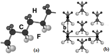 | ||
| Fig. 1 The structure of PVDF: (a) structure of the all-trans conformations showing the planar carbon backbone with attached fluorine and hydrogen atoms; (b) the crystal structure of the β-phase.17 | ||
Crystalline structure
With regard to characterizing the attributes of the membranes' mechanical strength and impact resistance, polymer crystallinity and the outcome membrane morphology are two remarkable parameters. Study of PVDF crystalline structure shows five different polymorphs, i.e., α, β, γ, δ, and ε phases, depending on the crystallization conditions.A wide of research has been done on the different crystal phases of PVDF, and α- and β-phases are of great interest due to their unique properties. The α-phase has a molecular chain combination of trans–gauche (TGTG), placing the F and H atoms alternately on each side of the chain, and is also the most thermodynamically stable phase, while the β-phase shows the highest dipolar moment per unit cell with the highest piezoelectric coefficient.10,18 The crystalline structures of these forms are shown in Fig. 2.19
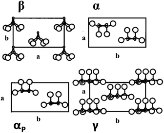 | ||
| Fig. 2 Crystalline structure of β, α, αP, and γ phases of PVDF projected onto the a–b plane of the unit cell. Large circles are fluorine atoms, small circles means dot carbon atoms, and hydrogen atoms are omitted.19 | ||
Fig. 3 shows multiple crystalline polymorphs, namely α, β, γ, δ, and ε related to PVDF.20 The crystallization of PVDF can be controlled by molecular weight, molecular weight distribution, polymerization method, cooling rate, and thermal history, and the crystallinity can range from 35% to 70%.21 Moreover, another factor affecting the morphology and crystal structure of the PVDF membrane is the coagulation medium. However, the crystallinity of all membranes remained intact, and all membranes exhibited a crystal-type structure. PVDF films are mostly biaxially or uniaxially rolled or stretched to ameliorate their electrical and mechanical properties or to effect conversion from one form to another. For instance, stretching α-samples will generate β-material since the molecular chains of form β are more extended than those of form α.11,20
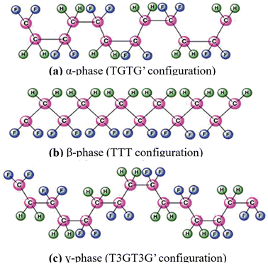 | ||
| Fig. 3 Chemical structure of the three main phases of PVDF.20 | ||
Wang et al.22 detected a similar outcome of coagulation bath temperature on the crystallinity structure. Better crystallinity is exhibited in a membrane fabricated from a 15 °C bath temperature than a 60 °C coagulation bath. They also reported that a membrane precipitated at 60 °C only appeared with a common crystal structure, while at the lowest temperature (15 °C), the PVDF crystallites consisted of a mixture of crystal forms. The coagulation medium is another factor besides precipitation temperature that affected the crystal structure and morphology of the PVDF membrane.
Lin et al.,20 intriguingly, noticed the formation of larger spherulites in membrane morphology by dissolving PVDF in DMF at disparate temperatures and immersing the cast membranes in a 1-octanol coagulation bath. However, the crystallinity of all membranes remained and all membranes exhibited an unaffected type of crystal structure. On the other hand, Wang et al.23 found astounding changes in the morphology of PVDF membranes prepared at several temperatures in N,N-dimethylacetamide (DMAc). They observed that the cross-sections of all membranes were composed of an interconnected structure with cavities, a type of crystal structure. However, by increasing the dissolving temperature, the size of the holes becomes more extensive.
Chen et al.23 discovered that 1-octanol in both the casting solution and coagulation bath formed a PVDF membrane influenced by the crystallization process. The particulate size decreases when the crystallization proceeds liquid–liquid demixing, with increasing 1-octanol content in doping solution.
Gregorio used Fourier transform infrared (FTIR) and X-ray diffraction (XRD) spectroscopy to determine the three crystalline phases formed in films prepared under different conditions and found a relationship between crystallization and membrane properties, such as morphology and mechanical strength.20 Some crystallographic data for the polymorphs of PVDF are listed in Table 2.
| The unit cell (Å) | The unit (g cm−3) | Space group | Structure | Molecular chain | Electroactive properties | |
|---|---|---|---|---|---|---|
| α-phase | a = 4.96 | 1.92 | P21/c | Monoclinic | TGTG′ | Low polarity |
| b = 6.94 | ||||||
| c = 4.62 | ||||||
| β-phase | a = 8.58 | 1.97 | Cm2m | Orthorhombic | TTTT | Largest polarity |
| b = 4.91 | ||||||
| c = 2.56 | ||||||
| γ-phase | a = 4.96 | 1.92 | P21/cn | Orthorhombic | T3GT3G′ | Medium polarity |
| b = 6.94 | ||||||
| c = 4.62 |
Thermal stability of PVDF
Thermal stability is defined as the ability of a fluid to resist breaking down under heat stress. The maximum use temperature is thus suggested to be the maximum temperature to which the fluid can be heated before the fluid begins to break down or degrade at an appreciable rate. PVDF thermal stability was evaluated by comparing TGA and DTG thermograms of PVDF unaged, aged in bioethanol and annealed for times of 30 and 90 days.24 Studies of PVDF demonstrate that the thermal degradation mechanism in PVDF in vacuum mostly starts with the loss of hydrogen fluoride (HF), sometimes referred to as dehydrochlorination (Fig. 4). In consequence, this led to many chemical reactions, such as the formation of cross-linking of the polymer or carbon–carbon double bonds (–C![[double bond, length as m-dash]](https://www.rsc.org/images/entities/char_e001.gif) C–). In addition, inhomogeneous thermal degradation of PVDF at a high temperature (∼160 °C) was observed by Lovinger and Reed. Inhomogeneous discoloration of the samples was caused by many spherulitic forms in PVDF, which degraded differently. This degradation process occurred mostly in the crystalline regions (not in the amorphous ones). Other possible reactions including the formation of free radicals were also proposed by Madorsky.20 Furusho et al.,25 by using a torsional braid analysis (TBA) method, worked on the thermal degradation of PVDF that was perceived to be among the most thermally stable halogen-containing polymers. Because of the high electronegativity of fluorine atoms on the chain, fluoropolymers are thermally more stable than hydrocarbon polymers, which causes the perfect thermal stability of PVDF.26
C–). In addition, inhomogeneous thermal degradation of PVDF at a high temperature (∼160 °C) was observed by Lovinger and Reed. Inhomogeneous discoloration of the samples was caused by many spherulitic forms in PVDF, which degraded differently. This degradation process occurred mostly in the crystalline regions (not in the amorphous ones). Other possible reactions including the formation of free radicals were also proposed by Madorsky.20 Furusho et al.,25 by using a torsional braid analysis (TBA) method, worked on the thermal degradation of PVDF that was perceived to be among the most thermally stable halogen-containing polymers. Because of the high electronegativity of fluorine atoms on the chain, fluoropolymers are thermally more stable than hydrocarbon polymers, which causes the perfect thermal stability of PVDF.26
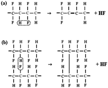 | ||
| Fig. 4 Schematic diagram of the mechanism of dehydrochlorination in PVDF: (a) formation of double bonds in the chain and (b) cross-linking of the polymer.16 | ||
Piezoelectricity of PVDF
In 1880, while the Curie brothers were working on some crystals such as quartz, they discovered piezoelectricity (pressure electricity) effects. The converse piezoelectric effect was proven using fundamental thermodynamic principles in 1881.27 The root of the word piezoelectricity comes from the Greek word meaning stress. Electrical charges appear by mechanical stress on piezo materials. Conversely, mechanical strain will be generated if an electrical field is used on this material. These are the direct and reverse piezoelectric effects (eqn (1)).28 Kawai discovered the strong piezoelectric effect in polyvinylidene fluoride (PVDF) in 1969, which comes from C–F bonds, then Bergman et al. and Nakamura showed the pyroelectric effect of PVDF in 1971.26| D = dT+ εE | (1) |
| X = sT + dE | (2) |
The piezoelectric constants of PVDF depend on the stretch ratio, temperature, crystallinity, and poling conditions.29 A piezoelectric matrix can characterize the piezoelectric properties of PVDF; the first matrix is for the film poled without stretching and the second is for the film after uniaxial stretching.
If the material is poled after uniaxial stretching:
The d-constant is the one most frequently used. The only non-zero components of the d-matrix are d31, d32, d33, d24. The first subscript defines the direction of displacement or the electric field, during the second, the direction of stress or strain.
The two principle modes of operation for energy harvesters are d31 and d33, which are based on the directions of polarization and stress (Fig. 5).30 The d31 coefficient is a transverse coefficient, which defines the electric polarization created toward the direction perpendicular to the applied stress direction. While the d33 coefficient is the longitudinal coefficient, which depicts the electric polarization produced in the same direction as the applied stress. The electrodes were arranged vertical to the poling direction in the d31 and d33 modes, which means the electric field is aligned with the polarization.20
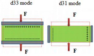 | ||
| Fig. 5 The piezoelectric d33 and d31 modes.20 | ||
Measuring piezoelectric constants in PVDF is very common, detecting the resulting voltage or current on its surfaces by applying a sinusoidal elongational force along with the polymeric film. Another method includes measures of strain or stress induced by a sinusoidal electric field or piezoelectric measurements at the resonant frequencies of electrically driven PVDF measures of strain or stress induced by a sinusoidal electric field. Static techniques for piezoelectric data generation involve applying hydrostatic pressure to PVDF films from an inert gas or employing an electric field, and measuring the resulting change in specimen thickness.19
Compared to other crystalline phases, the β-phase shows a higher dipole moment with higher electroactive (piezo, pyro, and ferroelectric) properties. Hence, improving the β-phase content in PVDF polymers with different methods is widely discussed.31 Some essential techniques are used to enhance the β-phase content in the polymer, which are different approaches to enhancing piezoelectricity in PVDF:
Pyroelectricity of PVDF
Electrical charges will appear under the effect of temperature for a material showing pyroelectric properties; the inverse (electric field changes the temperature) constitutes the electrocaloric effect. Thermodynamically, these are represented as:
 | (3) |
The heating of the specimen may be effected conductively, dielectrically, or by the use of frequency-modulated lasers. Generally, the dependence of pyroelectricity on experimental parameters is the same as described for piezoelectricity.33 The variation of the pyroelectric constant with poling field and a comparison of such constants for PVDF was shown by Kenney and Roth. Pyroelectric coefficients have been studied down to low temperatures (6 K) by Glass and Negran, and as a function of pressure by Scheinbeim et al.35 Pyroelectricity in PVDF remains stable for years and is fully reversible with temperature change.34,35
Study on β-phase improvements in PVDF structures
The β-phase is the significant crystal of PVDF because it is the most electroactive, displaying superior piezoelectricity and ferroelectricity. Thus, the top priority for investigators is to optimize the piezoelectric and ferroelectric advantages, manufacturing PVDF with a high β-phase fraction. The fraction of β-phase, F(β), can be calculated using the following equation:
 | (4) |
This equation is used to quantify the FTIR results. In fact, a formula is used to measure the transformation efficiency of the gauche state to the trans-state in PVDF samples. Here Xα and Xβ are the crystalline mass fractions of α- and β-phases and Aα and Aβ correspond to absorption bands at 763 and 840 cm−1, respectively. Table 3 shows that with an increase in deformation of the polymer chain in the β-phase with applied stress, the piezoelectric coefficient (d33) was enhanced, and the highest piezoelectricity for particular poling conditions is attained when the mechanical deformation provides a polymer with the highest polar β-phase.4
| Stretching ratio | F(β) (%) | d33 (pC/N) |
|---|---|---|
| 1 | 43 | 0 |
| 2 | 60.2 | 28 |
| 3 | 65.1 | 29 |
| 4 | 73.5 | 30.5 |
| 5 | 83.6 | 31 |
| 5.5 | 84.5 | 31.5 |
| 6 | 85.35 | 32.5 |
| 6.5 | 86.5 | 33 |
Thus, obtaining and increasing the β-phase is essential to having high piezoelectric and ferroelectric properties in PVDF synthesis. The mutual transformation between the three different three crystalline phases of PVDF can be controlled using different fabrication methods. The routes for increasing the amount of β-phase are shown in Fig. 6.4 Increasing the fraction of F(β) is the most important item in fabrication methods. As Fig. 6 shows, electric poling is one of the most important ways to obtain the β-phase. Other ways that can improve β-phase are cold stretching with high ratio, high-energy irradiation and annealing at high pressure. Fig. 7 shows % β-PVDF transformation from α-PVDF by different corona poling fields.
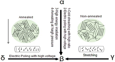 | ||
| Fig. 6 Mutual transformation routes and fabrication methods of different β-PVDF.37 | ||
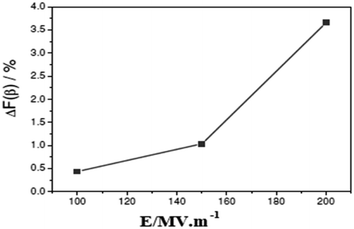 | ||
| Fig. 7 Evolution of the additional α → β phase transformation due to the different corona poling fields.38 | ||
Turning to some FTIR peaks of PVDF, the unshared peaks for the β-phase are close to 445, 473, and 1275 cm−1; spectrum peaks at 840 and 510 cm−1 are used to define β- and γ-phases. Moreover, the β- and γ-phases show very close peaks in the range of 1428–1432 cm−1. Therefore, the peaks at 1431 and 1429 cm−1 can operate as the defined bands of the β- and γ-phases, respectively.4 Fig. 8 shows the FTIR spectra of polymorphs of PVDF.
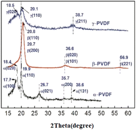 | ||
| Fig. 8 FTIR spectra of different crystalline polymorphs of PVDF: (a) α-phase, (b) γ-phase, (c) β-phase.39 | ||
A change in the orientation of the unit cell axes should also be perceived in X-ray diffraction measurements. Fig. 9 illustrates the XRD spectra of the main crystal phases of PVDF. The peaks at 2θ = 17.9°, 18.4°, 20.2°, 27.9°, 36.1°, and 39.0° are assigned to crystal planes 110, 020, 021, 111, 200, and 002, respectively, corresponding to the α-phase crystal plane. The diffraction peaks of the β-crystal phase are defined at 20.7°, 36.6°, and 56.9°, attributed to planes 110, 200, 020, 101, and 221, respectively.4
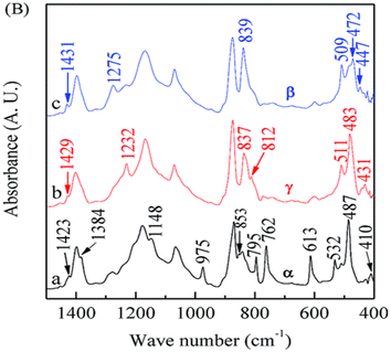 | ||
| Fig. 9 XRD patterns of various planes of different crystalline phases of PVDF.40 | ||
The 110 plane is the leading and most common plane in PVDF phases, and this plane might be a reasonable way to identify the β-crystal phase after making a mutual transformation. Fig. 10A illustrates an XRD analysis of the PVDF structure with a mechanical process that shows an extreme diffraction peak at 20.6, corresponding to β-PVDF that is attributed to 200 planes. At the same time, this peaks' diffraction at 20.2 and 19.9 correspond to the γ-phase and α-phase, respectively. Fig. 10B shows the same peak shifting in the prominent peak of PVDF with a chemical process to enhance the β-phase, and there are many more examples of this peak shifting, due to chemical, and mechanical treatment, among others.
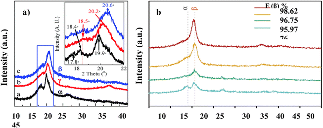 | ||
| Fig. 10 XRD patterns of the main peak of the crystalline phases of PVDF: (a) oriented,38 (b) composited.41 | ||
Conventional characterization techniques such as wide-angle X-ray diffraction (WAXD) have been employed to identify the stability of the β-phase after orientation. Fig. 11 shows (a) non-oriented PVDF and (b) oriented PVDF. The non-oriented crystal lattices all show Debye rings for planes corresponding to the α-phase. For example, the 110 plane, expressed as 110(α), has a complete ring in the edge, through, and end patterns. In contrast, there are no β-phase complete Debye rings in the non-oriented sample. The oriented crystal lattices show robust and complete Debye rings for 200 planes expressed as 200(β). 020, which is expressed as 020(β), is the other plane that shows all patterns, which implies an oriented structure with the β-phase. Thus WAXD could be a reasonable way to identify the β-phase.5
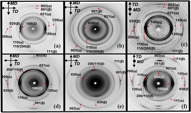 | ||
| Fig. 11 2D WAXD along the edge, through, and end directions of PVDF:6 (a) non-oriented along the edge direction, (b) non-oriented along the through direction, (c) non-oriented along the end direction, (d) oriented along with the edge direction, (e) oriented along the end direction.42 | ||
Fabrication techniques of piezoelectric PVDF
A number of fabrication methods have been introduced for producing piezoelectric PVDF-based materials and some of them are discussed and compared in this article. (e.g. melt blending, MEMS techniques, 3D printing, self-poling, electrospinning, soft lithography, drop-casting, solvent casting, composites and nanohybrid composites).Melt blending
One fabrication method for producing dielectric polymers is to melt them with other polymers. Melt-blowing is a unique, one-step process in which the melt of a polymer emerging from orifices is blown into super-fine fibers by hot, high-velocity air. A molten dielectric polymer can be blown into nanofibers and collected on a rotary drum or a forming belt with a vacuum underneath the surface to form a nonwoven web. By enhancing the micromorphology and crystallization behaviors of polymers, improved dielectric properties have been observed. For instance, several PLA–PVDF combined systems have been developed using the shear flow blending method, demonstrating improved dielectric properties. Continuous elongational flow can facilitate the distribution and orientation of the second phase in PLA/PVDF blends with a high viscosity ratio, resulting in enhancement of the efficient dielectric constant of PLA/PVDF blends; first the increasing trend is gentle and then linear with the growing amount of PVDF.433D printing technique
In recent years, three-dimensional printing (3D printing) has been applied to assemble electroactive fluoropolymer PEGs. A 3D-printed PVDF homopolymer can be deposited and poled with an electric-poling-assisted method. An ultimate decrease in generated charge is seen by increasing the electric field during 3D printing. Another method regarding 3D printing is solvent evaporation assisted (SEA) 3D printing. In SEA, piezoelectric nanoparticles are added to the polymer as a filler. In a study, flexible and transparent PVDF-TrFE structures were fabricated using the SEA method. The SEA 3D printing technique is a low-temperature and low-energy deposition method (Fig. 12).44 | ||
| Fig. 12 Images of 3D-printed PVDF-TrFE structures: (a) optical image of a layered PVDF-TrFE on top of a thin film, (b) cross-sectional HIM image of the structure, and (c) the top of the structure.44 | ||
Another method of 3D printing is fused deposition modeling (FDM). This method improves the diffusion of nanoparticles in polymer matrix nanocomposites and prevents nanoparticle agglomeration. Two step of filament extrusion and 3D printing are followed by thermal poling to enhance the piezoelectric response.
FTIR results have proved that a solvent-cast film has more β-phase content than 3D-printed films. Although the current output in the 3D-printed films was higher because of the uniform diffusion of nanoparticles and lack of porosities and cracks. All the above-mentioned properties in 3D-printed films are due to the filament extrusion process conducted in this method.45 The advantages of the 3D-printing technique include an improvement in piezoelectricity, freedom of design, and large-scale manufacturing of active biomaterials for actuators and sensors.
Self-poling
Self-poling is a simple, economic, extendable fabrication process used for highly sensitive piezoelectric devices, particularly ferroelectric nanogenerators. In this method, CH2/CF2 dipoles are oriented by the addition of external agents. In order to obtain a structure with a d33 value similar to that of PZT, a porous electret is used. In a study, the porous film's regionally oriented CH2/CF2 dipoles are attained by mixing ytterbium salt into PVDF.9Electrospinning
Electrospinning is probably the most popular and effective way to develop piezoelectric scaffolds with piezoelectric properties. A scaffold must resemble the extracellular matrix of tissues, meaning it has to be fiber shaped. Electrospinning can produce a fibrous structure with instant piezoelectricity.46 In electrospinning, a macroscale material will be reduced in size to uninterrupted continuous nanoscale fibers. The advantages of electrospinning are the ability to produce substrate-free structures, simple processes, and high inputs. Nanofibers produced by this method usually have circular cross-sections but other geometries (rectangular, coaxial) are possible.47 Electrospinning is a suitable method for PVDF nanofiber production with a high β-phase fraction and crystallinity by adjusting molecular dipoles with an applied voltage direction.48,49 Electrospinning has been used to precipitate and pole the PVDF-TrFE simultaneously; however, the poling procedure requires high electric fields. Limits of this technique also include the increase in cost and the risk of polymer breakdown.50PVDF is inherently hydrophobic and, as a result, it shows low cell attachment and spread. Surface modification is needed to activate the surface of PVDF and make it hydrophilic. Some surface modifications on PVDF are grafting chemical vapor deposition and plasma treatment. Plasma treatment has advantages over other methods because it does not need extra specialized equipment, and it modifies the surface homogeneously. Electrospinning and plasma treatment have been applied on PVDF surfaces for bone tissue applications. A Cellosaurus cell line was cultured on PVDF samples and control glass. There were no meaningful variations in the viability test and the spreading area measures. Comparing the results with the drop-casting method (Fig. 13 and 14) demonstrates no significant change in cell viability or spreading area measurements.45
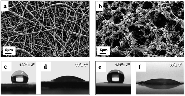 | ||
| Fig. 13 SEM micrographs of (a, c and d) electrospun vs. (b, e and f) drop-cast PVDF scaffolds. (c) and (e) show the contact angle of the scaffolds before oxygen treatment while (d) and (f) show it after oxygen treatment.45 | ||
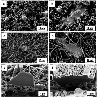 | ||
| Fig. 14 SEM micrographs of the behavior of Cellosaurus cells on (a, c and e) hydrophobic and (b, d and f) hydrophilic PVDF scaffolds. (a and b) are related to drop-cast, (c and d) to electrospun, and (e and f) to SEM-FIB cross-sections of electrospun scaffolds.45 | ||
The transient intracellular calcium concentration indicates growing osteoblasts on PVDF scaffolds with a ratio of 44![[thin space (1/6-em)]](https://www.rsc.org/images/entities/char_2009.gif) :
:![[thin space (1/6-em)]](https://www.rsc.org/images/entities/char_2009.gif) 46 on hydrophilic to hydrophobic scaffolds. However, in scaffolds made by the drop cast method, the transients ratio was 15
46 on hydrophilic to hydrophobic scaffolds. However, in scaffolds made by the drop cast method, the transients ratio was 15![[thin space (1/6-em)]](https://www.rsc.org/images/entities/char_2009.gif) :
:![[thin space (1/6-em)]](https://www.rsc.org/images/entities/char_2009.gif) 18 on hydrophilic to hydrophobic samples, and on the glass control (5%). It has been concluded that hydrophilicity does not significantly affect the number of active cells in any of the samples (Fig. 15). This result proves that plasma treatment does not affect the piezoelectric properties and the scaffolds produce a local electric field that initiates cell growth.
18 on hydrophilic to hydrophobic samples, and on the glass control (5%). It has been concluded that hydrophilicity does not significantly affect the number of active cells in any of the samples (Fig. 15). This result proves that plasma treatment does not affect the piezoelectric properties and the scaffolds produce a local electric field that initiates cell growth.
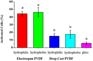 | ||
| Fig. 15 The percentage of activated cells on hydrophilic/hydrophobic electrospun and drop-cast PVDF scaffolds.45 | ||
The results also indicated that in electrospun scaffolds, the β-phase is predominant, while in drop cast scaffolds, the γ-phase is the primary phase.
Solvent casting
Solvent casting is one of the easiest ways to produce polymeric scaffolds. In this method, the polymer and additives, such as nanoparticles and plasticizers, are dissolved in a volatile solvent; after mixing, the solution is cast in the desired mold (Fig. 16). Following the evaporation of the solvent, the structure can undergo surface treatment. Major drawbacks of solvent casting include poor dispersion and agglomeration of nanoparticles in the solution (due to the difference in hydrophilic nature of the polymer and nanoparticles), brittleness, an opaque appearance, and high porosity of the final structure, which affects the piezoelectric and dielectric properties of nanocomposite as well as its strength.45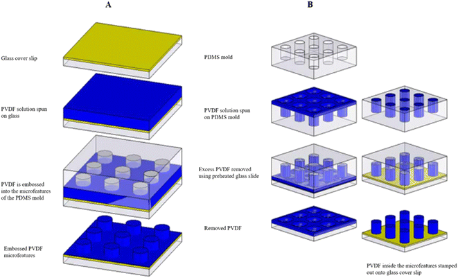 | ||
| Fig. 16 Illustration of the process of (A) embossed and (B) singular PVDF microstructures.51 | ||
Soft-lithography-based techniques
A method for the fabrication of PVDF microstructures is soft lithography. This method ensures accurate geometries at the microscale. Pillars, parallel lines, and crisscrossed lines are some structures applicable to this method. SEM (Fig. 17) and fluorescence microscopy proved adequate cell attachment, propagation, and intense interaction with the micro-discontinuities in microfabricated piezoelectric PVDF structures made by soft lithography.51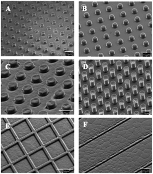 | ||
| Fig. 17 SEM images of (A and B) singular and (C and D) embossed columns, (E) crisscrossed, and (F) parallel channels.51 | ||
MEMS techniques
Micromachine molding, spin-coating, and screen-printing piezoelectric polymer solutions over the mold are multistep techniques used to make dome/bump-shaped piezoelectric films by Li et al.50 (see Fig. 18–20).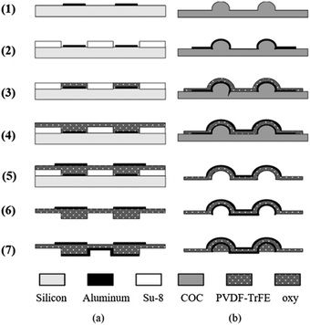 | ||
| Fig. 18 Summary of soft lithography fabrication steps for bump-shaped films.50 | ||
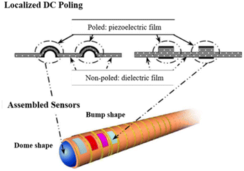 | ||
| Fig. 19 Schematic of a new mold-transfer method to trim the PVDF-TrFE piezoelectric polymer film and a new dome/bump-shaped tactile sensor module for a smart microcatheter.50 | ||
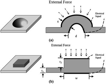 | ||
| Fig. 20 Scheme and operating principle of the dome/bump-shaped flexible PVDF-TrFE tactile sensors: (a) dome shaped, (b) bump shaped.50 | ||
Composite techniques
A material that is produced from two or more constituents is called a composite. The type of reinforcement and the reinforcement to matrix ratio enable engineers to tailor the material's properties. There are different approaches to preparing a composite, including micro-embossing processes, a layer-by-layer method, nanomaterials introduced into the matrix (nanohybrids), and finally a combination of the base polymer with other materials (blend composites).In the micro-embossing process, polymer actuators have deflection limitations. They are usually made by sticking a piezoelectric stripe to a substrate and making a composite. The composite interface must be kept without deformation or aging. One way to design and fabricate a piezoelectric polymer composite is to use the micro-embossing process used for temperature-sensitive, flexible polymers. Generally, microactuators are shaped as a unimorph cantilever simulated to optimize design parameters for large deflections (Fig. 21). A research group has developed a PVDF-based cantilever with a metalized nickel–copper alloy electrode layer. The tip deflection is related to the thickness of both the piezo and non-piezo layers. This technique can be applied to a wide range of piezoelectric microactuators.
 | ||
| Fig. 21 PVDF composite cantilever.52 | ||
Another way to prepare a composite is the layer-by-layer method using symmetric electrodes of a metal-core piezoelectric fiber known as SMPF printed on a matrix to make a vibration sensor. Bian et al.53 developed a composite with PVDF as the piezoelectric layer and molybdenum wire as the metal core to mimic the structure of a hair (Fig. 22). The vibration sensor has a cantilever beam structure, and the SMPF can detect vibrational amplitude, the direction of the matrix, the harmonic excitation frequency, and the vibration direction. They melted the PVDF particles and used an extrusion system with Mo-wire in the middle. By adjusting the extrusion speed of PVDF and molybdenum, the phase conversion rate of PVDF is kept under control. When the extrusion speed of Mo-wire is higher than that of PVDF, the molten PVDF will experience mechanical stretching, thus transitioning from α- to β-phase.53
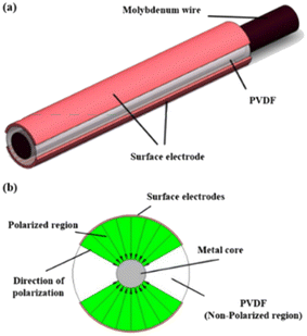 | ||
| Fig. 22 (a) The structure of the SMPF. (b) The cross-section of the SMPF and polarization distribution.53 | ||
In nano-filled (nanohybrid) composites we are able to take advantage of conventional filler technology with the help of nanoparticles to achieve enhanced mechanical, thermal, and electrical properties in materials. In a study conducted by Gaur et al., two types of PVDF-based nanohybrids were prepared (Fig. 23). The first one was compromised of PVDF and an eggshell membrane, and the other was a system made of same ingredients with nanoclay. Nanohybrid films were covered by aluminum as a conducting layer, and the electrodes were placed on them. The structure was then encapsulated in PDMS to prevent damage. Eggshell alone does not change the PVDF structure. However, nanoclay and eggshell combinations transform the matrix into a piezoelectric phase. The eggshell improved the energy harvesting capability of the nanohybrid composite. The produced nanohybrid was proven to be fully biocompatible in terms of cell viability, attachment, and propagation, and it is likely to be used as a nanogenerator for medical self-regulating, monitoring, and diagnostics.5
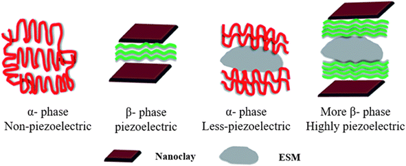 | ||
| Fig. 23 Schematics of nano-hybrid structural orientations under different conditions with the presence of ESM, nanoclay, and a combination of both.4 | ||
Composites and copolymers of PVDF
PVDF composites with nanostructure materials can improve performance. Therefore, PVDF and its copolymers have been appreciably studied because of their significant ability to couple electrical and mechanical properties, structural flexibility, high piezoelectric coefficient, high elastic compliance, intrinsic biocompatibility, reasonable properties, mechanical strength, and good chemical resistance to acids, solvents, and bases.7,54 They are suitable for divergent energy harvesting applications due to other properties like low density, light weight, low refractive index, and low cost index. Also, they offer different design configurations by patterning electrodes on the surface and poling only the required portion.55 There are several reports in literature on the enhanced performance of PVDF-based nanocomposite structures. How to collect the generated instantaneous charge and power electronic devices continuously are key challenges for energy harvesting using piezoelectric polymers.56As mentioned in Table 4, (P(VDF-TrFE)) is a ferroelectric material with remarkable chemical stability, piezoelectric effect, and biocompatibility and its nanofiber mats because of their flexibility, light weight, and low cost as a functional material for flexible tactile sensors, have attracted increasing attention recently. It is feasible to obtain a better piezoelectric response than PVDF thin films, with highly stretchable structures, and large effective working areas. Furthermore, the β-phase of P(VDF-TrFE) indicates preferential crystallization and high piezoelectricity. Even if PVDF generally presents a higher degree of crystallinity, the TrFE content facilitates crystallization in the polymer chain, resulting in a higher content of the β-phase. The organization and spherulite size of polymers and copolymers on the surface morphology are divergent. Meantime, P(VDF-TrFE) flexible piezoelectric fibers achieved aligned arrangements, in which the polymer chains exhibited a strong preferential orientation and the piezoelectric performance was enhanced. Thus, electrospun P(VDF-TrFE) mats were used as the core piezoelectric layer in a tactile sensor and friction-functional layers were fabricated on flexible films, which worked under piezoelectric and triboelectric hybrid stimulation.18 Baozhang Liu et al.,64 by doping AgNWs into PVDF via electrospinning, prepared PVDF/Ag nanowire (AgNW) composite nanofibers. They observed that by adding AgNWs, the content of β-phase in PVDF increased, and the piezoelectricity of PVDF nanofibers was greatly enhanced due to the interactions between the AgNWs and the PVDF matrix, which forces the PVDF chains to form β-phases. The β-phase and sensitivity were found to be enhanced when augmenting the content of AgNW. The sensitivity of PVDF/AgNWs nanocomposite nanofibers used for pressure sensors can achieve 30 pC/N.
| Composite | Improved properties | Applications | Reference |
|---|---|---|---|
| Poly(vinylidene fluoride-hexafluoropropylene) (PVDF-HFP) | Piezoelectric effect, chemical stability, and biocompatibility | Micro energy development in flexible, wearable electronic devices and wireless sensor networks | 57 |
| Poly(vinylidene fluoride trifluoroethylene) (P(VDF-TrFE)) | Flexibility, chemical stability, and biocompatibility | Electrodes were screen-printed on a multi-layered P(VDF-TrFE) structure | 58 |
| Type of ferroelectric material with significant piezoelectric effect | |||
| Poly(vinylidene cyanide-vinyl acetate) (P[VDCN-VAC]), and (vinylidene fluoride-tetrafluoroethylene) (P[VDF-TeFE]), and poly(vinylidene fluoridehexafluoropropylene) (P[VDF-HFP]) | Piezoelectric effect, light weight, flexibility, and low cost | Flexible tactile sensors | 20 and 59 |
| No need for stretching or drawing of the polymer chain. Even if poling is necessary to increase the piezoelectric effect | |||
| Polyaniline (PANI) – zinc ferrite – drop casting technique to prepare the ternary PVDF composite (80 mm) | PANI helps to prevent the internal resistance of the nanogenerator and stabilize the output voltage. Improves the homogeneity of filler distribution in the composite. Zinc ferrite nanorods improve the mechanical and piezoelectric properties | Nanogenerator and stabilize the output voltage | 60 |
| Lanthanum-doped lead zirconate titanate (PLZT) – PVDF composite with PLZT | In 50 vol% CNT film the polar phase was obtained. Piezoelectric constant augmented to 30 pC/N for 50 vol% PLZT-PVDF. Energy density raised to 29.1 mg cm−3 | Energy-harvesting devices | 20 |
| Piezoelectric output | |||
| PVDF fibers were prepared using electrospinning – graphene oxide (GO) and reduced graphene oxide (rGO) | RGO and GO nanofillers help to improve the piezoelectric properties. The filler content gives a powerful interfacial interaction with the PVDF chain | Energy-harvesting devices, portable electronics, wearable devices and pressure sensors | 61 |
| Ca3(PO4)2 nanorod-incorporated PVDF films have been prepared via an in situ flexible piezoelectric nanogenerator | The addition of different molar concentrations of Ca3(PO4)2 accelerated the nucleation of electroactive crystallization. Also achieves huge dielectric value by the in situ process (interfacial polarization) | Charge cell phones, small portable electronic gadget | 20 |
| PVDF-ZnO nanofiber mats prepared with electrospinning | Modified in the crystal structure and improvement in the electrical output | As an elevated energy-scavenging interface, it can provide a simple, effective, flexible and cost-effective approach to self-powering microelectronics apparel for several applications | 62 |
| BaTiO3–PVDF composite nanofibers | Improvement in the polymer phase crystallization and increase in piezoelectrically generated voltage | Offers a simple and flexible methodology to self-power microelectronics and nanogenerator on behalf of several applications in industry, medicine and others | 63 |
PVDF biocompatibility and applications
Due to the outstanding properties of PVDF, such as high flexibility, ease of processing, long-term stability, light weight, high chemical corrosion resistance, non-degradability, and biocompatibility, PVDF is a promising candidate for wide applications in the fields of medical textiles and piezoelectric generators. For application in medical products, the PVDF is more often spun by a melt spinning process which is used for medical applications like vascular grafts, ligaments, and artificial corneas. In the following, several cases of the uses of PVDF in this field are discussed (Table 5).| Recent development | Properties | Applications | Reference |
|---|---|---|---|
| Polyamide, polydioxanone and PVDF | Excellent physical and mechanical | Surgical sutures and meshes to replace polypropylene (PP) | 65 |
| PVDF monofilament sutures | Superior biocompatibility and mechanical properties | Alternative suture material with barbs, used effectively for tendon repair | 66 |
| PTFE-PVDF-PP membranes | Revealed no significant histopathological change | Eyeball implants in rabbits | 68 |
| Composites of PVDF and HAP | No toxicity in vitro, and raised wettability | Bone regeneration applications, medical and dental implants | 69 |
| a β-PVDF-based electrospun scaffold | Mechanical stability in adherence, differentiation of cardiomyocytes | Repairing damaged heart muscles and stem cells, cardiac patch | 71 |
| Composites of PVDF-reduced graphene oxide | Reduced graphene oxide promotes β-phase in PVDF and improves the wettability to a large degree | More cell adherence, spread, and proliferation in the case of human umbilical vein endothelial cells | 72 |
Some cell lines in the human body, such as corneal, epidermal, retinal, vascular endothelial cells, and nervous systems, are controlled by electric signals. Piezoelectric signals are also found in parts of the body like bone, cartilage, DNA, ligaments, skin, and tendons.8 One reason why engineers are looking for active biomaterials is that cell lines such as osteoblasts and chondrocytes demand external mechanical or electrical stimuli for enhanced tissue repair. Conductive and piezoelectric biomaterials are a major category of active biomaterials used to fabricate ideal scaffolds for specific applications.50
PVDF is naturally hydrophobic, which limits its application in pharmacy and as a biomaterial. To overcome this drawback, several approaches have been applied. These approaches can fall into two categories: physical and chemical modifications. Coating, depositing, immobilizing, and cross-linking a hydrophilic polymer on PVDF is considered physical modification, while electron beam radiation, plasma treatment, and chemical reactions are chemical modifications.67
Yu et al.70 fabricated a mesoporous PVDF-based piezoelectric nanogenerator and encapsulated it within polydimethylsiloxane (PDMS). They implanted the aforementioned device in a rat's quadriceps femur muscle surface to test its in vivo biocompatibility. After extracting the films, there was no evidence of cellular toxicity or muscular atrophy, just limited inflammatory infiltrates. The spongy mesoporous film showed excellent flexibility and biocompatibility, and it did not lose its efficiency during this time. For long-term use of this device, it was exposed to an ultrasonic bio-fluid bath. They showed that sandwiched PVDF NG could serve as a long-life implantable powering system in the future.
In research conducted by Gallego et al.,51 soft-lithography-based techniques were used to make individual and embossed PVDF microstructures with delicate geometries. Tests showed that the material has biocompatibility, and intense interaction between cells and substrate occurred. A remarkable piezoelectric response was achieved due to poling and actuation. To resist gastric acid and intestinal juice, duodenal barriers must have thermal stability, corrosion, and abrasion resistance. PVDF composites seem to be best for these applications; moreover, they barely stick to the intestine wall, and due to their antibacterial properties, they demonstrated negligible adverse effects.68
Despite superior mechanical properties and chemical resistance, PVDF lacks microbial resistance. To overcome this drawback, quaternary pyridinium monomers have been grafted on PVDF and showed extreme antimicrobial properties.73
Another piece of research conducted to enhance the biocompatibility of PVDF was done via oxygen plasma and dopamine coating. The results show that oxygen plasma treatment for a short time improved PVDF biocompatibility up to four-fold, and dopamine coating created a strongly adhesive hydrophilic surface with a threefold enhancement in biocompatibility.74
Studying PVDF as a neural scaffold membrane indicates that neither pure PVDF nor one loaded with multiwalled CNTs has the potential to support neurite branching, but they are permissible for oligodendrocyte morphological differentiation.75
Interestingly, the addition of reduced graphene oxide to polyvinylidene fluoride promotes wettability and β-phase formation in PVDF, resulting in higher cell adhesion and proliferation and biocompatibility of the composite.72
It is known that piezoelectrical scaffolds generate electricity, facilitating angiogenesis and nerve restoration. In this concept, the biocompatibility of a composite of PVDF–PCL was tested with rat Schwann cells. Cell proliferation and differentiation were observed as well as biodegradation in 4 months.76 In vivo testing of nanogenerators may face some critical issues. Bio-fluid–NG interaction, ion diffusion in NG, detachment of tissue from NG, and the tissue response to high local electricity produced by piezoelectric materials are unknown.70
Piezoelectric materials can convey an electric motive without an external energy source; thus they are considered promising candidates in injured tissues. PVDF has high chemical stability for use in membranes, electrolytes, and catalysis for wastewater treatment77 and filtration technology, bioreactors, distillation, gas separation,78 separators for lithium-ion batteries,79 etc. Owing to its high piezoelectricity, pyro and ferroelectric properties as well as low density, toughness, and flexibility, it has applications in wearable functional devices,80 transducers81 and sensors (chemical, pressure, impact, audio, ultrasonic and biosensors), health monitoring systems, biomaterials, and flexible actuator devices.1 In electronic devices, such as speakers, LCDs, LEDs, watches, and telecommunication devices, piezoelectric ignition systems measure the mechanical and physical changes under shock loading.82
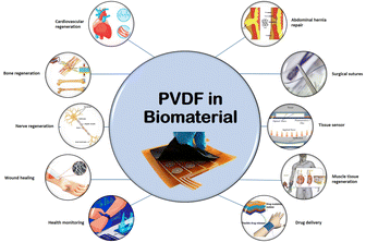
PVDF as a biomaterial has been used in bone,45 neural83 and muscle tissue regeneration,84 abdominal hernia repair,85 endothelialization, vascular surgery,66 and tissue sensors. PVDF copolymers and PVDF-TrFE have also been reported as bone regeneration, neural tissue, and wound healing fibers and membranes.85
PVDF-based piezopolymers have applications in bone because of their characteristic of power generation under small mechanical deformation. Crystalline micelles in collagen molecules induce piezoelectricity. Consequently, the extracellular matrix of cells is the reason for the piezoelectric effect in bone tissue. Hence, scaffolds similar to ECM are in demand in bone rehabilitation.46
PVDF is now being used in the medical industry as medical textiles and surgical meshes, drug delivery, tissue engineering, surgical sutures, and implants.66 PENG devices based on PVDF have the flexibility to achieve twistable, foldable characteristics, and stretchability, which is ideal for wearable electronics such as biomechanical monitoring units or energy supply units (Fig. 24).86
Future directions
PVDF as a piezoelectric material is being used in the medical industry, for tissue engineering, surgical sutures, surgical meshes, drug delivery, and implants and is also used in other wide applications. In recent years, PVDF has gained a lot of attention as a major ingredient in energy harvesting and medical applications due to its many benefits, which showed using PVDF as a piezoelectric material is a thoughtful choice.The knowledge discussed in this review on the design and fabrication of laboratory-scale piezoelectric PVDF-based materials provides a better understanding for prospective scientists and ongoing studies in the fields of energy harvesting and sensors. Indeed, even for a specific application, rarely can one cure provide all the appropriate properties. Although several studies have evaluated the efficacy of combined factors, there is still a pressing need to develop an ideal structure and fabrication methodology for different piezoelectric applications. So far, most studies have been conducted on small size models and fabrication techniques. It is crucial to evaluate the performance of factors at a larger scale before industrial trials. In addition, the ability to scale up PVDF fabrication strategies is still an important consideration that needs to be addressed.
PVDF is a significant processible inorganic material whose final properties depend on its fabrication method, which has been shown to have excellent ferroelectric properties, and which could be the savior of scientific progress in the fields of energy harvesting and medicine in the future.
Conclusions
Considering that the crystallization of PVDF can be controlled, PVDF is a significant processible inorganic material whose final properties depend on its fabrication method, which has been shown to have excellent ferroelectric properties. Its remanent polarization is 0.05–0.1 C m−2, leading to large piezoelectricity in which the piezoelectric constant is 24–34 pC/N. The coercive field and Curie temperature of PVDF are larger than those of typical inorganic ferroelectrics. The phase transition in polymorphs of PVDF to achieve high piezoelectric properties, and the mechanism by which the orientation of the dipole moment of a unit cell is changed, are quite interesting. The electrospinning technique demonstrated potent efficacy with high β-phase fraction, as an effective way to develop piezoelectric properties.Author contributions
S. M. and S. A. wrote the article. R. B. contributed to the supervision, conceptualization, methodology, validation, writing – review & editing, project administration, as well as funding acquisition. All authors contributed to the discussion.Conflicts of interest
There are no conflicts to declare.Acknowledgements
The support provided by Institute for Advanced Textile Materials and Technologies (ATMT), and the Shanghai Belt & Road Project: Science and Technology Commission of Shanghai Municipality (Grant no: 20520741500) are highly appreciated.References
- S. Guo, X. Duan, M. Xie, K. C. Aw and Q. Xue, Composites, fabrication and application of polyvinylidene fluoride for flexible electromechanical devices: A review, Micromachines, 2020, 11(12), 1–29 CrossRef PubMed.
- H. Wang and A. Jasim, Piezoelectric energy harvesting from pavement, in Eco-Efficient Pavement Construction Materials, Elsevier, 2020, pp. 367–382 Search PubMed.
- R. S. Dahiya and M. Valle, Appendix A Fundamentals of piezoelectricity, Robot. Tactile Sens., 2013, vol. 1, pp. 195–245 Search PubMed.
- A. Ansari, M. M. Mohebi, S. Baghshahi and R. Tabarzadi, The effect of tantalum substitution on the microstructure and dielectric and piezoelectric properties of Pb0.99(Zr0.95Ti0.05)0.98Nb0.02O3 ceramics, J. Mater. Sci.: Mater. Electron., 2018, 29(20), 17948–17955 CrossRef.
- A. Gaur, S. Tiwari, C. Kumar and P. Maiti, A bio-based piezoelectric nanogenerator for mechanical energy harvesting using nanohybrid of poly(vinylidene fluoride), Nanoscale Adv., 2019, 1(8), 3200–3211 RSC.
- J. Wang, L. Zhou, C. Zhang, and Z. Lin Wang, Small-Scale Energy Harvesting from Environment by Triboelectric Nanogenerators, A Guide to Small-Scale Energy Harvest. Tech., 2020 Search PubMed.
- K. K. Sappati and S. Bhadra, Piezoelectric polymer and paper substrates: A review, Sensors, 2018, 18(11), 3605 CrossRef PubMed.
- C. Ribeiro, V. Sencadas, D. M. Correia and S. Lanceros-Méndez, Piezoelectric polymers as biomaterials for tissue engineering applications, Colloids Surf., B, 2015, 136, 46–55 CrossRef CAS.
- S. K. Ghosh, et al., Yb3+ assisted self-polarized PVDF based ferroelectretic nanogenerator: A facile strategy of highly efficient mechanical energy harvester fabrication, Nano Energy, 2016, 30, 621–629 CrossRef CAS.
- Z. He, F. Rault, M. Lewandowski, E. Mohsenzadeh and F. Salaün, Electrospun PVDF Nanofibers for Piezoelectric Applications: A Review of the Influence of Electrospinning Parameters on the β Phase and Crystallinity Enhancement, Polymers, 2021, 13(2), 174 CrossRef CAS PubMed.
- J. Chang, M. Dommer, C. Chang and L. Lin, Piezoelectric nanofibers for energy scavenging applications, Nano Energy, 2012, 1(3), 356–371 CrossRef CAS.
- M. S. Vijaya, Piezoelectric materials and devices: applications in engineering and medical sciences, CRC Press, 2012 Search PubMed.
- R. Yue, S. G. Ramaraj, H. Liu, D. Elamaran, V. Elamaran, V. Gupta, S. Arya, S. Verma, S. Satapathi and X. Liu, A review of flexible lead-free piezoelectric energy harvester, J. Alloys Compd., 2022, 165653 CrossRef CAS.
- P. Bhavya, S. Verma and S. Arya, Fabric-Based Wearable Self-Powered Asymmetric Supercapacitor Comprising Lead-Free Perovskite Piezoelectrodes, Adv. Mater. Technol., 2022, 2200079 Search PubMed.
- J. E. Dohany, Fluorine-containing polymers, poly(vinylidene fluoride), Kirk-Othmer Encycl. Chem. Technol., 2000 Search PubMed.
- F. Liu, N. A. Hashim, Y. Liu, M. R. M. Abed and K. Li, Progress in the production and modification of PVDF membranes, J. Membr. Sci., 2011, 375(1–2), 1–27 CrossRef CAS.
- S. Ducharme, T. J. Reece, C. M. Othon and R. K. Rannow, Ferroelectric polymer Langmuir-Blodgett films for nonvolatile memory applications, IEEE Trans. Device Mater. Reliab., 2005, 5(4), 720–735 CAS.
- L. Ruan, X. Yao, Y. Chang, L. Zhou, G. Qin and X. Zhang, Properties and Applications of the β Phase Poly (vinylidene fluoride), Polymers, 2018, 10(3), 228 CrossRef PubMed.
- G. M. Sessler, Piezoelectricity in polyvinylidenefluoride, J. Acoust. Soc. Am., 1981, 70(6), 1596–1608 CrossRef CAS.
- S. Sukumaran, S. Chatbouri, D. Rouxel, E. Tisserand, F. Thiebaud and T. Ben Zineb, Recent advances in flexible PVDF based piezoelectric polymer devices for energy harvesting applications, J. Intell. Mater. Syst. Struct., 2021, 32(7), 746–780 CrossRef CAS.
- J. Martín, D. Zhao, T. Lenz, I. Katsouras, D. M. de Leeuw and N. Stingelin, Solid-state-processing of δ-PVDF, Mater. Horiz., 2017, 4(3), 408–414 RSC.
- X. Wang, L. Zhang, D. Sun, Q. An and H. Chen, Formation mechanism and crystallization of poly (vinylidene fluoride) membrane via immersion precipitation method, Desalination, 2009, 236(1–3), 170–178 CrossRef CAS.
- X. Wang, X. Wang, L. Zhang, Q. An and H. Chen, Morphology and formation mechanism of poly (vinylidene fluoride) membranes prepared with immerse precipitation: effect of dissolving temperature, J. Macromol. Sci., Part B: Phys., 2009, 48(4), 696–709 CrossRef CAS.
- A. J. de Jesus Silva, M. M. Contreras, C. R. Nascimento and M. Ferreira da Costa, Kinetics of thermal degradation and lifetime study of poly (vinylidene fluoride)(PVDF) subjected to bioethanol fuel accelerated aging, Heliyon, 2020, 6(7), e04573 CrossRef PubMed.
- F. Noboru, T. Komatsu and T. Nakagawa, A Study of the Thermal Degradation of Several Halogen-containing Polymers by Torsional Braid Analysis, Bull. Chem. Soc. Jpn., 1974, 47(7), 1573–1577 CrossRef.
- J. Yu, X. Huang, C. Wu and P. Jiang, Permittivity, thermal conductivity and thermal stability of poly (vinylidene fluoride)/graphene nanocomposites, IEEE Trans. Dielectr. Electr. Insul., 2011, 18(2), 478–484 CAS.
- A. Jain, K. J. Prashanth, A. K. Sharma, A. Jain and P. N. Rashmi, Dielectric and piezoelectric properties of PVDF/PZT composites: A review, Polym. Eng. Sci., 2015, 55(7), 1589–1616 CrossRef CAS.
- P. Dineva, D. Gross, R. Müller, and T. Rangelov, Piezoelectric materials, in Dynamic fracture of piezoelectric materials, Springer, 2014, pp. 7–32 Search PubMed.
- S. J. Lee, A. P. Arun and K. J. Kim, Piezoelectric properties of electrospun poly(l-lactic acid) nanofiber web, Mater. Lett., 2015, 148, 58–62 CrossRef CAS.
- K. S. Ramadan, D. Sameoto and S. Evoy, A review of piezoelectric polymers as functional materials for electromechanical transducers, Smart Mater. Struct., 2014, 23(3), 33001 CrossRef CAS.
- F. Cardoso, et al., 4th ESO–ESMO international consensus guidelines for advanced breast cancer (ABC 4), Ann. Oncol., 2018, 29(8), 1634–1657 CrossRef CAS.
- S. G. Hunagund, S. M. Harstad, A. A. El-Gendy, S. Gupta, V. K. Pecharsky and R. L. Hadimani, Investigating phase transition temperatures of size separated gadolinium silicide magnetic nanoparticles, AIP Adv., 2018, 8(5), 56428 CrossRef.
- P. C. A. Hammes and P. P. L. Regtien, An integrated infrared sensor using the pyroelectric polymer PVDF, Sens. Actuators, A, 1992, 32(1–3), 396–402 CrossRef CAS.
- A. M. Glass and T. J. Negran, A note on the origin of pyroelectricity in polyvinylidene fluoride, J. Appl. Phys., 1979, 50(8), 5557 CrossRef.
- K. T. Chung, B. A. Newman and J. I. Scheinbeim, The pressure and temperature dependence of piezoelectric and pyroelectric response of poled unoriented phase I poly (vinylidene fluoride, J. Appl. Phys., 1982, 53(10), 6557–6562 CrossRef.
- B. Mohammadi, A. A. Yousefi and S. M. Bellah, Effect of tensile strain rate and elongation on crystalline structure and piezoelectric properties of PVDF thin films, Polym. Test., 2007, 26(1), 42–50 CrossRef.
- P. Taylor, K. Tashiro, and M. Kobayashi, Phase Transitions: A Multinational Structural phase transition in ferroelectric fluorine polymers: X- ray diffraction and infrared/Raman spectroscopic study structural phase transition, in Ferroelectric Fluorine Polymers : X-Ray Diffraction and Infra, April 2013, pp. 37–41 Search PubMed.
- V. Sencadas, R. Gregorio and S. Lanceros-Méndez, α to β phase transformation and microestructural changes of PVDF films induced by uniaxial stretch, J. Macromol. Sci., Part B: Phys., 2009, 48(3), 514–525 CrossRef.
- X. Cai, T. Lei, D. Sun and L. Lin, A critical analysis of the α, β and γ phases in poly(vinylidene fluoride) using FTIR, RSC Adv., 2017, 7(25), 15382–15389 RSC.
- W. Xia and Z. Zhang, PVDF-based dielectric polymers and their applications in electronic materials, IET Nanodielectrics, 2018, 1(1), 17–31 CrossRef.
- A. Mahdavi Varposhti, M. Yousefzadeh, E. Kowsari and M. Latifi, Enhancement of β-Phase Crystalline Structure and Piezoelectric Properties of Flexible PVDF/Ionic Liquid Surfactant Composite Nanofibers for Potential Application in Sensing and Self-Powering, Macromol. Mater. Eng., 2020, 305(3), 1–8 CrossRef.
- K. Tashiro, et al., High-Electric-Field-Induced Hierarchical Structure Change of Poly(vinylidene fluoride) as Studied by the Simultaneous Time-Resolved WAXD/SAXS/FTIR Measurements and Computer Simulations, Macromolecules, 2021, 54(5), 2334–2352 CrossRef.
- H. Zhang, X. Wei and J.-P. Qu, Microstructure evolution and mechanism of PLA/PVDF hybrid dielectrics fabricated under elongational flow, Polymer, 2021, 224(April), 123719 CrossRef.
- N. A. Shepelin, et al., 3D printing of poly(vinylidene fluoride-trifluoroethylene): A poling-free technique to manufacture flexible and transparent piezoelectric generators, MRS Commun., 2019, 9(1), 159–164 CrossRef.
- H. Kim, T. Fernando, M. Li, Y. Lin and T. L. B. Tseng, Fabrication and characterization of 3D printed BaTiO3/PVDF nanocomposites, J. Compos. Mater., 2018, 52(2), 197–206 CrossRef.
- M. Kitsara, et al., Permanently hydrophilic, piezoelectric PVDF nanofibrous scaffolds promoting unaided electromechanical stimulation on osteoblasts, Nanoscale, 2019, 11(18), 8906–8917 RSC.
- K. Maleckis, Towards Precision Nanomanufacturing For Mechanical Design: From Individual Nanofibers To Mechanically Biomimetic Nanofibrillary Vascular Grafts, 2017 Search PubMed.
- Y. Xin, J. Zhu, H. Sun, Y. Xu, T. Liu and C. Qian, A brief review on piezoelectric PVDF nanofibers prepared by electrospinning, Ferroelectrics, 2018, 526(1), 140–151 CrossRef.
- S. M. Damaraju, S. Wu, M. Jaffe and T. L. Arinzeh, Structural changes in PVDF fibers due to electrospinning and its effect on biological function, Biomed. Mater., 2013, 8(4), 45007 CrossRef.
- C. Li, P. M. Wu, S. Lee, A. Gorton, M. J. Schulz and C. H. Ahn, Flexible dome and bump shape piezoelectric tactile sensors using PVDF-TrFE copolymer, J. Microelectromech. Syst., 2008, 17(2), 334–341 Search PubMed.
- D. Gallego, N. J. Ferrell and D. J. Hansford, Fabrication of piezoelectric polyvinylidene fluoride (PVDF) microstructures by soft lithography for tissue engineering and cell biology applications, Mater. Res. Soc. Symp. Proc., 2007, 1002, 13–18 CrossRef.
- Y. Fu, E. C. Harvey, M. K. Ghantasala and G. M. Spinks, Design, fabrication and testing of piezoelectric polymer PVDF microactuators, Smart Mater. Struct., 2006, 15, 1 CrossRef.
- Y. Bian and R. Liu, Fabrication of a biomimetic piezoelectric polyvinylidene difluoride (PVDF) fibre with a metal core and its application in vibration sensors, Trans. Inst. Meas. Control, 2018, 40(1), 3–11 CrossRef.
- S. Mishra, L. Unnikrishnan, S. K. Nayak and S. Mohanty, Advances in piezoelectric polymer composites for energy harvesting applications: a systematic review, Macromol. Mater. Eng., 2019, 304(1), 1800463 CrossRef.
- R. A. Surmenev, et al., Hybrid lead-free polymer-based nanocomposites with improved piezoelectric response for biomedical energy-harvesting applications: A review, Nano Energy, 2019, 62, 475–506 CrossRef.
- I.-H. Kim, D. H. Baik and Y. G. Jeong, Structures, electrical, and dielectric properties of PVDF-based nanocomposite films reinforced with neat multi-walled carbon nanotube, Macromol. Res., 2012, 20(9), 920–927 CrossRef.
- D. Ponnamma, O. Aljarod, H. Parangusan and M. A. A. Al-Maadeed, Electrospun nanofibers of PVDF-HFP composites containing magnetic nickel ferrite for energy harvesting application, Mater. Chem. Phys., 2020, 239, 122257 CrossRef.
- S. You, L. Zhang, J. Gui, H. Cui and S. Guo, A flexible piezoelectric nanogenerator based on aligned P (VDF-TrFE) nanofibers, Micromachines, 2019, 10(5), 302 CrossRef PubMed.
- J. Seo, J. Y. Son and W.-H. Kim, Structural and ferroelectric properties of P (VDF-TrFE) thin films depending on the annealing temperature, Mater. Lett., 2019, 238, 294–297 CrossRef.
- I. Chinya, A. Sasmal and S. Sen, Conducting polyaniline decorated in-situ poled Ferrite nanorod-PVDF based nanocomposite as piezoelectric energy harvester, J. Alloys Compd., 2020, 815, 152312 CrossRef.
- M. Z. Ongun, S. Oguzlar, E. C. Doluel, U. Kartal and M. Yurddaskal, Enhancement of piezoelectric energy-harvesting capacity of electrospun β-PVDF nanogenerators by adding GO and rGO, J. Mater. Sci.: Mater. Electron., 2020, 31(3), 1960–1968 CrossRef.
- M. S. S. Bafqi, R. Bagherzadeh and M. Latifi, Fabrication of composite PVDF-ZnO nanofiber mats by electrospinning for energy scavenging application with enhanced efficiency, J. Polym. Res., 2015, 22(7), 1–9 Search PubMed.
- A. D. Hussein, R. S. Sabry, O. A. A. Dakhil and R. Bagherzadeh, Effect of Adding BaTiO3 to PVDF as Nano Generator, J. Phys.: Conf. Ser., 2019, 1294(2), 22012 CrossRef.
- X. Wang, F. Sun, G. Yin, Y. Wang, B. Liu and M. Dong, Tactile-sensing based on flexible PVDF nanofibers via electrospinning: A review, Sensors, 2018, 18(2), 330 CrossRef.
- S. H. Im, C. Y. Kim, Y. Jung, Y. Jang and S. H. Kim, Biodegradable vascular stents with high tensile and compressive strength: A novel strategy for applying monofilaments via solid-state drawing and shaped-annealing processes, Biomater. Sci., 2017, 5(3), 422–431 RSC.
- Y. Huang, E. R. Cadet, M. W. King and J. H. Cole, Comparison of the mechanical properties and anchoring performance of polyvinylidene fluoride and polypropylene barbed sutures for tendon repair, J. Biomed. Mater. Res., Part B, 2022 Search PubMed.
- F. Dehghan, PVDF as A Biocompatible Substrate For Microfluidic Fuel Cells, 2020 Search PubMed.
- R. Leszczynski, E. Stodolak, J. Wieczorek, J. Orlowska-Heitzman, T. Gumula and S. Blazewicz, In vivo biocompatibility assessment of (PTFE-PVDF-PP) terpolymer-based membrane with potential application for glaucoma treatment, J. Mater. Sci.: Mater. Med., 2010, 21(10), 2843–2851 CrossRef CAS PubMed.
- F. José, C. Braga, S. Ota, A. Augusto, C. Universitária and S. P. Sp, Characterization of PVDF/HAP composites for medical applications, Mater. Res., 2007, 10(3), 247–251 CrossRef.
- Y. Yu, et al., Biocompatibility and in vivo operation of implantable mesoporous PVDF-based nanogenerators, Nano Energy, 2016, 27, 275–281 CrossRef CAS.
- R. Arumugam, E. S. Srinadhu, B. Subramanian and S. Nallani, β-PVDF based electrospun nanofibers – A promising material for developing cardiac patches, Med. Hypotheses, Jan. 2019, 122, 31–34 Search PubMed.
- S. Pei, F. Ai and S. Qu, Fabrication and biocompatibility of reduced graphene oxide/poly(vinylidene fluoride) composite membranes, RSC Adv., 2015, 5(121), 99841–99847 RSC.
- D. J. Han, et al., Poly(vinylidene fluoride)-based film with strong antimicrobial activity, Appl. Surf. Sci., 2021, 562, 150181 CrossRef CAS.
- D. Mangindaan, I. Yared, H. Kurniawan, J. R. Sheu and M. J. Wang, Modulation of biocompatibility on poly(vinylidene fluoride) and polysulfone by oxygen plasma treatment and dopamine coating, J. Biomed. Mater. Res., Part A, 2012, 100(11), 3177–3188 CrossRef.
- Ç. Defterali, et al., In vitro evaluation of biocompatibility of uncoated thermally reduced graphene and carbon nanotube-loaded PVDF membranes with adult neural stem cell-derived neurons and glia, Front. Bioeng. Biotechnol., 2016, 4(DEC), 1–19 Search PubMed.
- Y. Cheng, Y. Xu, Y. Qian, X. Chen, Y. Ouyang and W. E. Yuan, 3D structured self-powered PVDF/PCL scaffolds for peripheral nerve regeneration, Nano Energy, 2020, 69, 104411 CrossRef CAS.
- E. Yuliwati, A. F. Ismail, T. Matsuura, M. A. Kassim and M. S. Abdullah, Effect of modified pvdf hollow fiber submerged ultrafiltration membrane for refinery wastewater treatment, Desalination, 2011, 283, 214–220 CrossRef CAS.
- P. S. Goh and A. F. Ismail, Advances in nanocomposite membranes, Membranes, 2021, 11(3), 1–3 CrossRef PubMed.
- P. Chaturvedi, A. B. Kanagaraj, A. Alhammadi, H. Al Shibli and D. S. Choi, Fabrication of PVDF–HFP-based microporous membranes by the tape casting method as a separator for flexible Li-ion batteries, Bull. Mater. Sci., Jun. 2021, 44(2), 161 Search PubMed.
- Y. Lin, et al., Studies on the electrostatic effects of stretched PVDF films and nanofibers, Nanoscale Res. Lett., May 2021, 16(1), 1–10 Search PubMed.
- Y. H. Liu, et al., Wearable transparent PVDF transducer for photoacoustic imager in body sensor network, in IEEE International Ultrasonics Symposium, IUS, 2020, vol. 2020 Search PubMed.
- R. Dallaev, T. Pisarenko, D. Sobola, F. Orudzhev, S. Ramazanov and T. Tomáš, Brief Review of PVDF Properties and Applications Potential, Polymers, 2022, 14(22), 4793 CrossRef CAS PubMed.
- A. Zaszczynska, P. Sajkiewicz and A. Gradys, Piezoelectric scaffolds as smart materials for neural tissue engineering, Polymers, 2020, 12(1), 161 CrossRef CAS PubMed.
- P. M. Martins, et al., Effect of poling state and morphology of piezoelectric poly(vinylidene fluoride) membranes for skeletal muscle tissue engineering, RSC Adv., 2013, 3(39), 17938–17944 RSC.
- C. D. Klink, et al., Comparison of long-term biocompability of PVDF and PP meshes, J. Investig. Surg., 2011, 24(6), 292–299 CrossRef CAS.
- A. Venault, et al., Zwitterionic electrospun PVDF fibrous membranes with a well-controlled hydration for diabetic wound recovery, J. Membr. Sci., 2020, 598, 117648 CrossRef CAS.
Footnote |
| † These authors contributed equally. |
| This journal is © The Royal Society of Chemistry 2023 |


