 Open Access Article
Settling velocity variation induced by a sphere moving across a two-layer stratified fluid with different rheological characteristics
Jinghan Pan a,
Chengxu Tu*a,
Mengwen Kana,
Jiaming Shana,
Fubing Bao*a and
Jianzhong Linb
aZhejiang Provincial Key Laboratory of Flow Measurement Technology, China Jiliang University, Hangzhou 310018, China. E-mail: tuchengxu@cjlu.edu.cn; dingobao@cjlu.edu.cn
bKey Laboratory of Impact and Safety Engineering (Ningbo University), Ministry of Education, 315201 Ningbo, China
First published on 27th March 2023
Abstract
Particle settling in stratified fluids is widespread in chemical and pharmaceutical processes, and how to effectively regulate the particle velocity is the key to optimizing the above process technology. In this study, the settling of individual particle in two stratified fluids, water–oil and water–PAAm was studied using the high-speed shadow imaging method. In the Newtonian stratified fluid of water–oil, the particle penetrates the liquid–liquid interface and forms unsteady entrained drops of different shapes, and the settling velocity becomes smaller. In contrast, in water–PAAm stratified fluids, the shear-thinning and viscoelasticity of the lower fluid will cause the entrained drops of the particle to appear a stable sharp cone shape, and the particle can thus obtain a smaller drag coefficient ( < 1) and a significantly enhanced settling velocity (U* > 1) compared to the uncovered PAAm solution (PAAm solution without overlayer oil). This study can provide a new path for the development of new particle velocity regulation techniques.
1 Introduction
Particle settling is widespread in nature and industry, such as the flow of pollutant particles in the atmosphere,1 the movement of particles in the respiratory tract,2 and the petroleum industry,3 which are involved in the movement of particles and are currently a hot issue in the above-mentioned fields. In the geophysical environment, both miscible and immiscible fluids involve particle settling through fluid layered interfaces. Many of the characteristics of these systems are primarily due to density gradients caused by differences in temperature or salinity between fluids. Combining particle settling with stratified fluids is essential in many environmental processes and geophysical contexts, such as urban pollution,4 sediment fluxes in the ocean,5 and carbon sequestration.6 In oceanography, the presence of stratification phenomena such as temperature and salinity layers can affect the spread, survival, and growth of small biota.7 Liquid–liquid interfaces are widespread in industrial processes such as extraction, separation, or mixing. Therefore, particles crossing liquid–liquid interfaces have a high research value. Nevertheless, most research studies consider the movement of particles towards deformable interfaces, focusing on coalescence8 or motion near the interface,9 and only a few studies are devoted to liquid–liquid interface fracture.The question of how particles penetrate the interface has been a hot topic for researchers. Ding et al.10 and Raufaste et al.11 studied the formation process of cavities in gas–liquid interfaces by spherical and cylindrical particles impacting them and revealed the relationship between contact line pinning and subsequent cavity evolution. Maru et al.12 pointed out that whether a particle passes through an interface must also surely depend on surface energy and density difference, as much as critical radius. Geller et al.13 demonstrated two different liquid surface strain modes through numerical simulations: one is the Film Drainage Mode (FDM),8,14,15 in which the fluid is discharged in front of the particle, leaving a thinning film, and the other is the Tailing Mode (TM),12 in which the particle passes through a deformable interface while still being wrapped by the surrounding fluid. In most cases, particles passing through the stratified interface will increase the resistance of the fluid to particle motion.16 In the low Reynolds number range, the increased resistance to particles settling in linearly stratified fluids is due to the viscous entrainment of the fluid in the high-density layer and the formation of a lighter fluid shell behind the particles.17 At 1.5 < Re < 15, particles tend to drag the lighter fluid into the lower fluid, greatly increasing its drag; within 3 < Fr < 10, the drag coefficient in the stratified fluid is found to be an order of magnitude larger than that of the uniform fluid18 (the definition of Reynolds numbers (Re) and Froude numbers (Fr) is explained in Chapter 3). As the presence of stratification leads to a significant increase in the drag force of individual particles during settling, the particle settling velocity is significantly inhibited,19 and particles are even suspended in fluids lighter than themselves.20 Magnaudet et al.21 found that particles usually pull the upper fluid to the lower layer, and the resulting column settling kinetic properties are highly dependent on fluid density, viscosity, and Re.
Nevertheless, previous studies have paid less attention to particle settling when the lower fluid is a viscoelastic non-Newtonian fluid and rarely noticed the phenomenon of particle velocity enhancement in it. Zenit et al.22 found that in a non-Newtonian fluid, viscous force, inertial force, and surface tension all change. In this study, we will focus on the effects of key factors such as entrained drop shape, drag coefficient, and Re number on the variation of particle settling velocity in Newtonian-non-Newtonian stratified fluid.
2 Experimental method
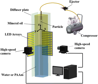
The experimental setup is shown in Fig. 1. The water tank is a sunken rectangular container of 1000 mm in height and 150 mm × 150 mm cross-section. The particle release device is a vacuum ejector to ensure that the initial velocity of the particles is zero. Two high-speed cameras (FASTCAM Mini UX 50, Photron), two LED arrays, and a computer connected to the cameras were used in the experiments to form a high-speed shadowgraph binocular-imaging system. The system can track the trajectory of particles in the x–y and x–z planes. Six types of spherical particles with less than a 0.25 μm diameter variation and spherical error and 0.02 μm of surface roughness were used in the experiments. The system includes polytetrafluoroethylene (PTFE) particles with diameters of 5 mm, 6.35 mm, 8 mm, and 9.53 mm, respectively, and also includes silicon nitride ceramic (Si3N4) and zirconium oxide ceramic (ZrO2) particles with diameters of 5 mm. Mineral oil (Sigma-Aldrich M5904) was used as the upper fluid, and water and 0.5 wt% polyacrylamide (PAAm, supplied by Shanghai Macklin Biochemical Co., Shanghai, China) were selected as the lower fluid, respectively, thus constituting two types of stratified fluids. The shear thinning and viscoelastic properties of the PAAm solution are specifically described in our recent paper.23The density of the PAAm solution is 1005 kg m−3, which is very close to that of water. The shear thinning and viscoelastic properties of 0.5% PAAM solution are shown in Fig. 2. Considering the variation of temperature on the properties of the fluid, each experiment was controlled at room temperature, and the temperature of the experimental fluid was measured using a standard thermostat with an error of ±0.1 °C to keep the temperature range at 20 ± 5 °C.
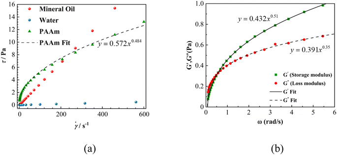 | ||
| Fig. 2 (a) Rheogram of 0.5 wt% PAAm solution, water, and mineral oil. (b) Viscoelastic modulus of PAAm solution as a function of frequency. | ||
Fig. 2a shows the rheological curves of the shear stress τ to the shear rate ![[small gamma, Greek, dot above]](https://www.rsc.org/images/entities/i_char_e0a2.gif) with a steady state in the PAAm solution and water, where the slope of the curves represents the fluid viscosity (η). Fig. 2b indicates that the storage modulus G′ and loss modulus G′′ increased with the increasing frequency, which indicates the yield behavior of the test solution.
with a steady state in the PAAm solution and water, where the slope of the curves represents the fluid viscosity (η). Fig. 2b indicates that the storage modulus G′ and loss modulus G′′ increased with the increasing frequency, which indicates the yield behavior of the test solution.
Boundary extraction of the particles and extraction of kinetic parameters such as displacement and velocity were performed using ImageJ and a self-written MATLAB code. In this paper, the capillary effect is overcome by increasing the particle density so that the particles are sufficient to cross the interface and the particles all reach the final velocity before reaching the liquid–liquid boundary.
3 Results and discussion
3.1 Force analysis
Firstly, gravity and buoyancy are analyzed. For a spherical particle with radius R, the particle density is ρs, and the densities of the upper and lower fluids are ρ1 and ρ2, respectively, where ρs is greater than ρ1 and ρ2. Fig. 3 shows a simple force model for an individual particle. The presence of liquid droplets attached to the tail of the settling particle after the particle settles through the stratified interface leads to a change in the overall force on the particle.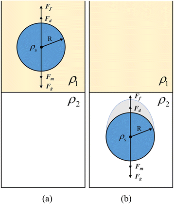 | ||
| Fig. 3 Schematic diagram of individual particle forces. (a) Schematic diagram of the upper layer fluid force, (b) schematic diagram of the lower layer fluid force. | ||
Firstly, the forces on the particle in the upper fluid are analyzed, where the gravity and buoyancy of the particle are constant. The gravity of the particle in the upper fluid layer is
 | (1) |
The buoyancy of the particle during the settling process is
 | (2) |
 | (3) |
According to D'Alembert's principle
| Fm + Fg = Ff + Fd | (4) |
For the force on the particle in the lower fluid, the presence of droplets attached to the tail of the particle leads to a change in the force on the particle, mainly gravity, buoyancy, and drag.
The gravity of the particle in the lower fluid is
 | (5) |
The buoyancy of the particle in the lower fluid is
 | (6) |
The shape of the droplet in the experiment of oil–PAAm stratified fluids is mostly conical. According to the equivalent volume method, the volume of the droplet is obtained by subtracting the volume of the hemisphere from the volume of the cone and is expressed as
 | (7) |
τ = k![[small gamma, Greek, dot above]](https://www.rsc.org/images/entities/i_char_e0a2.gif) n n
| (8) |
For the 0.5 wt% PAAm solution, n is 0.484, and k is 0.572 (goodness-of-fit is 0.997) obtained by fitting the above equation and rheogram of 0.5 wt% PAAm solution.23
The Reynolds number (Re) is defined as
 | (9) |
The modified Reynolds number (Re*) of the settling particle in the shear-thinning fluid is25
 | (10) |
 | (11) |
 | (12) |
In shear thinning fluid, the drag force can be expressed as26
 | (13) |
The drag coefficient is
 | (14) |
In addition, the Froude number (Fr) was introduced
 | (15) |
| Particle | Density (g cm−3) | Oil–water stratification | Oil–PAAm stratification | ||
|---|---|---|---|---|---|
| Oil (Re) | Water (Re) | Oil (Re) | PAAm (Re*) | ||
| 5 mm PTFE | 2.2 | 35.4 | 1316.0 | 35.2 | 1.14 |
| 5 mm Si3N4 | 3.2 | 53.9 | 2594.0 | 54.3 | 5.26 |
| 5 mm ZrO2 | 6.0 | 89.8 | 3933.1 | 90.8 | 20.43 |
| 6.35 mm PTFE | 2.2 | 57.6 | 2122.5 | 57.4 | 3.44 |
| 8 mm PTFE | 2.2 | 92.5 | 3524.7 | 92.8 | 9.89 |
| 9.53 mm PTFE | 2.2 | 126.2 | 4518.9 | 127.6 | 19.16 |
3.2 Morphology
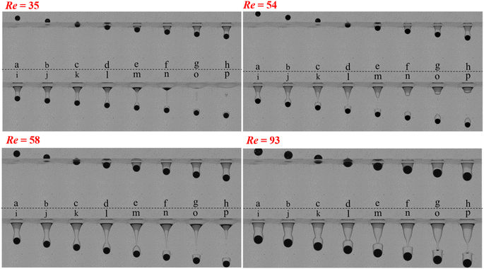
The evolutionary pattern of different particles near the oil–water interface is given in Fig. 4. As the particle penetrates the layered interface, a film of upper fluid is attached to the front of the particle, and the upper fluid near the surface of the particle is carried simultaneously into the lower fluid by inertia, and a cone-shaped column of fluid is entrained at the end of the particle.27,28 The cone-shaped column is elongated as the particle settles, and at a certain critical distance, the column breaks under the combined effect of surface tension and lower hydrostatic pressure. The droplet remains attached to the tail of the particle after the column has broken (Fig. 4). The shape of the entrained drop varies with the initial Re, tending to a hat-shaped cap (Re = 35), a gyroscopic shape (Re = 54) or a platform shape (Re = 58, Re = 93) under surface tension and vortex dynamics.As the initial Re number increases, it is possible for the light fluid attached at the tail of the particle to take on a different geometry. The elongation of the liquid column maintains an axisymmetric geometry until it breaks, independent of the viscosity of the lower fluid. The shape of the trailing entrained drops of the settling particle, the volume of the cone-shaped liquid column, and the distance of the column break also vary with the Re number. Also, the process is related to the inertia, viscosity, buoyancy, and capillary effects of the particle.28
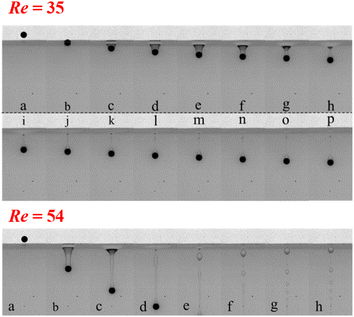
As shown in Fig. 5, unlike the cone-shaped liquid column formed at the interface of the oil–water stratification, the particle crosses the oil–PAAm layered interface, and an elongated cylindrical column is formed in the lower fluid, indicating that the capillary effect plays little role in this process21 and suggesting a shear thinning effect in the lower fluid. With the particle settling, the cylindrical liquid column entrapped at the end of the particle becomes thinner and thinner, relaxing and taking on multiple necking under the combined effects of capillary, viscous, and buoyancy. The break in necking is accompanied by the production of multiple droplets, which may be due to the classical mechanism of capillary wave instability or to a surface tension-driven contraction process.28 The entrained drops show a sharp cone shape under the viscoelasticity of the lower fluid (PAAm solution), which directly confirms the presence of a negative tail of the particle.29
3.3 Sedimentation trajectory
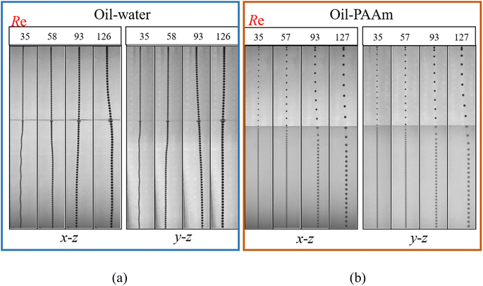
For particle settling, many studies have been done before.30 Particles form vortex rings and streamwise vortices in their wake during settling, and the shedding of vortices leads to the movement of individual particles that do not have a stable path and can be broadly classified as inclined linear, vertical linear, and zigzag oscillatory settling.From the diagram of the settling trajectory of the oil–water layer (Fig. 6a), it can be seen that the particle mostly shows a straight line movement in the upper layer (oil). As the initial Re increases, the path of the particle shows instability before reaching the delamination interface, which is due to the shedding of the vortices during the settling process of the particle, causing their motion instability. After entering the lower fluid, the particle show mostly non-linear motion, with the most unstable settling trajectory at Re = 35. This is due to the fact that during each motion cycle, the particle generates four vortex rings in different directions.30 However, the particle settling paths in the lower fluid of the oil–PAAm stratification fluid (Fig. 6b) almost always show straight lines. If the particle is entering the lower fluid at a large inclination angle (with respect to the direction of gravity, z direction), the particle will slowly change to a linear motion in the direction of gravity in the PAAm solution. This is mainly due to the specific shear thinning properties of the PAAm solution,31 in contrast to the significant lateral migration that occurs in oil–water stratified fluids.
3.4 Analysis of particle settling velocity in stratified fluids
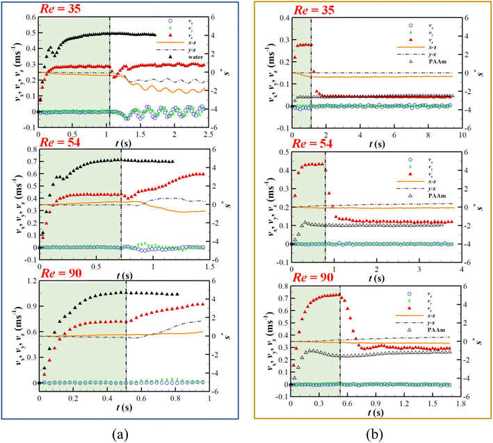
Fig. 7 shows the variation in settling velocity and lateral migration of a single particle in stratified fluids. At about t = 0.3 s, all particles almost reach their final steady velocity in the upper fluid (oil). This is due to the fact that the particle crosses the interface and entrains the upper fluid into the lower fluid, forming a column of fluid connected to the upper fluid. The dragging by the liquid column on the particle leads to a period of decelerated motion, which is consistent with previous results.28 The subsequent breakage of the liquid column leads to a reduction in drag, and the particle velocity in the water increases firstly with time and then stabilises, reaching its final steady velocity. In Fig. 7a, comparing the settling velocity of the particle in an oil–water stratified fluid and uncovered water, it is found that the particle settling is at smaller velocities in the stratified fluid than in water alone. This is due to the particles that have entrained drops on their tails when settling in the lower fluid (water), resulting in increased buoyancy and drag forces on the particle. At the same time, it was found that the final steady velocity in oil-water fluids increased with increasing initial Re.As shown in Fig. 7b, the particle settling velocity decreases rapidly after crossing the oil–PAAm interface and tends to a final steady velocity in the uncovered PAAm solution. This deceleration shows a different pattern to that of the oil-water stratified fluid. Unexpectedly, the settling velocity of the particle in the lower fluid (PAAm solution) was enhanced compared to the uncovered PAAm solution fluid. The larger the initial Re, the stronger the inertial effect of the particle and the faster the settling velocity. After entering the lower fluid, the shear effect of the PAAm solution fluid increases, the viscosity decreases, and the drag force decreases. On the other hand, the droplets are sharp cone-shaped by the viscoelasticity of the lower fluid, and the overall shape of the particles and droplets tends to be more streamlined, making them less subject to the drag force. There is a significant lateral migration of particle settling in the lower fluid of the oil–water stratified fluid, whereas almost vertically in the oil–PAAm stratified fluid, with vx and vy always fluctuating around zero and almost independent of the initial Re.
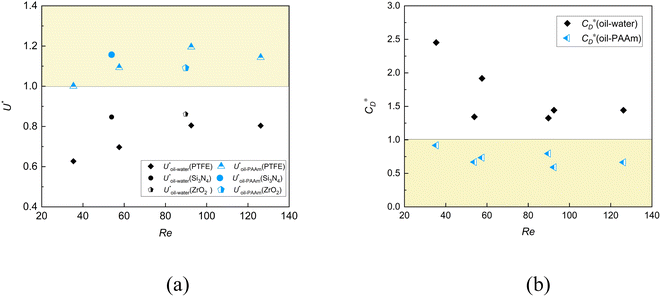
In the lower layer of the oil–water stratified fluid, the entrained drops of the particle take the shape of the hat, gyroscope, and platform, while in the oil–PAAm stratified fluid, the shear-thinning and the viscoelasticity of the lower fluid cause the entrained drops of the particle to take the shape of a stable sharp cone. The change in velocity is actually due to the introduction of entrained drops, which changes the drag coefficient of the composite particle formed by the combination of particle and entrained drops. The internal mechanism of velocity enhancement is illustrated by comparing the change of particle drag coefficient in uncovered PAAm solution or in water with that in stratified fluid. As shown in Fig. 8, in the lower layer of the oil–PAAm stratified fluid, the particle obtains a smaller drag coefficient ( < 1), which significantly enhances the settling velocity (U* > 1) compared to the uncovered PAAm solution fluid.
4 Conclusions
In this paper, the settling characteristics of an individual particle in oil–PAAm stratified and oil–water stratified fluids and the evolution law near the stratification interface during this process are studied using high-speed shadow imaging. The results show that the lateral migration velocity fluctuations of the particle in shear-thinning viscoelastic fluids (PAAm solution) are smaller, and the path is more stable compared to Newtonian fluids (water). The particle penetrating the stratified interface will drag the upper fluid into the lower fluid to form a liquid column. The shape and fracture position of the liquid column are closely related to the Re and the type of stratified fluid. When the lower fluid is water, the liquid column is conical and breaks near the top of the particle; when the lower fluid is PAAm solution, the liquid column appears as an elongated column under the effect of shear-thinning characteristics and weak surface tension. At this time, the particle-entrapped liquid column will undergo multiple necking and rupture, resulting in a series of discrete droplets. The particle tail entrained drops are sharp cone-shaped under the influence of viscoelasticity and shear-thinning characteristics. The sharp cone shape of the entrained drops reduces the drag coefficient of the particle and accelerates the settling of the particle. This is very different from the general Newtonian stratified fluid. The results of this study will help to deepen the understanding of particle settling laws in Newtonian-non-Newtonian stratified fluids and develop new particle settling velocity regulation techniques for chemical and other engineering applications.Data availability
The data that support the findings of this study are available from the corresponding author upon reasonable request.Conflicts of interest
There are no conflicts to declare.Acknowledgements
This work was supported by the National Natural Science Foundation of China (Grant No. 11972334, 12272367, 12132015), the Key R & D Program of Zhejiang Province (2021C01099) and the Fundamental Research Funds for the Provincial Universities of Zhejiang (2020YW06, 2020YW19).References
- H. Rügner, M. Schwientek, B. Beckingham, B. Kuch and P. Grathwohl, Turbidity as a proxy for total suspended solids (TSS) and particle facilitated pollutant transport in catchments, Environ. Earth Sci., 2013, 69, 373–380 CrossRef.
- T. T. Zhang, B. Gao, Z. X. Zhou and Y. Chang, The movement and deposition of PM2. 5 in the upper respiratory tract for the patients with heart failure: an elementary CFD study, Biomed. Eng., 2016, 15, 517–530 Search PubMed.
- S. Malhotra and M. M. Sharma, Settling of spherical particles in unbounded and confined surfactant-based shear thinning viscoelastic fluids: An experimental study, Chem. Eng. Sci., 2012, 84, 646–655 CrossRef CAS.
- H. Fernando, S. Lee, J. Anderson, M. Princevac, E. Pardyjak and S. Grossman-Clarke, Urban fluid mechanics: air circulation and contaminant dispersion in cities, Environ. Fluid Mech., 2001, 1, 107–164 CrossRef CAS.
- J. T. Turner, Zooplankton fecal pellets, marine snow and sinking phytoplankton blooms, Aquat. Microb. Ecol., 2002, 27, 57–102 CrossRef.
- J. H. Stillman, S. C. Lefebvre, K. M. Okimura, T. Komada, A. E. Parker, M. K. Drake, P. E. Rossignol, E. J. Carpenter and I. Benner, Nitrogen source and pCO2 synergistically affect carbon allocation, growth and morphology of the coccolithophore Emiliania huxleyi: potential implications of ocean acidification for the carbon cycle, Global Change Biol., 2012, 18, 493–503 CrossRef.
- A. Doostmohammadi, R. Stocker and A. M. Ardekani, Low-Reynolds-number swimming at pycnoclines, Proc. Natl. Acad. Sci. U. S. A., 2012, 109, 3856–3861 CrossRef CAS PubMed.
- J. Eggers, J. R. Lister and H. A. Stone, Coalescence of liquid drops, J. Fluid Mech., 1999, 401, 293–310 CrossRef CAS.
- K. Danov, T. Gurkov, H. Raszillier and F. Durst, Stokes flow caused by the motion of a rigid sphere close to a viscous interface, Chem. Eng. Sci., 1998, 53, 3413–3434 CrossRef CAS.
- H. Ding, B. Q. Chen, H. R. Liu, C. Y. Zhang, P. Gao and X. Y. Lu, On the contact-line pinning in cavity formation during solid-liquid impact, J. Fluid Mech., 2015, 783, 504–525 CrossRef.
- C. Raufaste, G. Kirstetter, F. Celestini and S. J. Cox, Deformation of a free interface pierced by a tilted cylinder, Europhys. Lett., 2012, 99, 24001 CrossRef.
- H. Maru, D. Wasan and R. Kintner, Behavior of a rigid sphere at a liquid—liquid interface, Chem. Eng. Sci., 1971, 26, 1615–1628 CrossRef CAS.
- A. Geller, S. Lee and L. Leal, The creeping motion of a spherical particle normal to a deformable interface, J. Fluid Mech., 1986, 169, 27–69 CrossRef CAS.
- A. R. Thomson, Recent developments in protein recovery and purification, J. Chem. Technol. Biotechnol., 1984, 34, 190–198 CrossRef.
- P. G. Smith and T. G. M. Van De Ven, The effect of gravity on the drainage of a thin liquid film between a solid sphere and a liquid/fluid interface, J. Colloid Interface Sci., 1984, 100, 456–464 CrossRef CAS.
- N. Dietrich, S. Poncin and H. Z. Li, Dynamical deformation of a flat liquid–liquid interface, Exp. Fluids, 2011, 50, 1293–1303 CrossRef.
- K. Y. Yick, C. R. Torres, T. Peacock and R. Stocker, Enhanced drag of a sphere settling in a stratified fluid at small Reynolds numbers, J. Fluid Mech., 2009, 632, 49–68 CrossRef CAS.
- A. N. Srdić-Mitrović, N. A. Mohamed and H. J. S. Fernando, Gravitational settling of particles through density interfaces, J. Fluid Mech., 1999, 381, 175–198 CrossRef.
- R. Camassa, C. Falcon, J. Lin, R. M. Mclaughlin and R. Parker, Prolonged residence times for particles settling through stratified miscible fluids in the Stokes regime, Phys. Fluids, 2009, 21, 031702 CrossRef.
- N. Abaid, D. Adalsteinsson, A. Agyapong and R. M. Mclaughlin, An internal splash: Levitation of falling spheres in stratified fluids, Phys. Fluids, 2004, 16, 1567–1580 CrossRef CAS.
- J. Magnaudet and M. J. Mercier, Particles, drops, and bubbles moving across sharp interfaces and stratified layers, Annu. Rev. Fluid. Mech., 2020, 52, 61–91 CrossRef.
- R. Zenit and J. J. Feng, Hydrodynamic interactions among bubbles, drops, and particles in non-Newtonian liquids, Annu. Rev. Fluid. Mech., 2018, 50, 505–534 CrossRef.
- S. S. Yang, C. X. Tu, M. L. Dai, X. F. Ge, R. J. Xu, X. Y. Gao and F. B. Bao, Sedimentation of Two Side-by-Side Heavy Particles of Different Density in a Shear-Thinning Fluid with Viscoelastic Properties, Appl. Sci., 2021, 11, 7113 CrossRef CAS.
- P. A. Reynolds and T. E. R. Jones, An experimental study of the settling velocities of single particles in non-Newtonian fluids, Int. J. Miner. Process., 1989, 25, 47–77 CrossRef CAS.
- A. Acharya and M. RA, Flow of inelastic and viscoelastic fluids past a sphere. II. Anomalous separation in the viscoelastic fluid flow, Rheol. Acta, 1976, 15, 471–478 CrossRef.
- A. Acharya, R. A. Mashelkar and J. Ulbrecht, Flow of inelastic and viscoelastic fluids past a sphere, Rheol. Acta, 1976, 15, 454–470 CrossRef.
- J. L. Pierson and J. Magnaudet, Inertial settling of a sphere through an interface. Part 1. From sphere flotation to wake fragmentation, J. Fluid Mech., 2018, 835, 762–807 CrossRef.
- J. L. Pierson and J. Magnaudet, Inertial settling of a sphere through an interface. Part 2. Sphere and tail dynamics, J. Fluid Mech., 2018, 835, 808–851 CrossRef.
- O. G. Harlen, The negative wake behind a sphere sedimenting through a viscoelastic fluid, J. Non-Newtonian Fluid, 2002, 108, 411–430 CrossRef CAS.
- M. Horowitz and C. H. K. Williamson, The effect of Reynolds number on the dynamics and wakes of freely rising and falling spheres, J. Fluid Mech., 2010, 651, 251–294 CrossRef.
- N. Goyal and J. J. Derksen, Direct simulations of spherical particles sedimenting in viscoelastic fluids, J. Non-Newtonian Fluid, 2012, 183, 1–13 Search PubMed.
| This journal is © The Royal Society of Chemistry 2023 |

