 Open Access Article
Polyimide aerogel-derived amorphous porous carbon/crystalline carbon composites for high-performance microwave absorption†
Ziqing Wang a,
Yonggang Min
 *a,
Jiyong Fang
 *b,
Wentao Yu
 a,
Wanjun Huanga,
Xiaochuang Lua and
Bolin Wanga
aSchool of Materials and Energy, Guangdong University of Technology, Guangzhou 510006, China. E-mail: ygmin@gdut.edu.cn
bMidea Corporate Research Center, Foshan, China. E-mail: fangjiyong1989@foxmail.com
First published on 1st March 2023
Abstract
High-performance polyimide-based porous carbon/crystalline composite absorbers (PIC/rGO and PIC/CNT) were prepared by vacuum freeze-drying and high-temperature pyrolysis. The excellent heat resistance of polyimides (PIs) ensured the integrity of their pore structure during high-temperature pyrolysis. The complete porous structure improves the interfacial polarization and impedance-matching conditions. Furthermore, adding appropriate rGO or CNT can improve the dielectric losses and obtain good impedance-matching conditions. The stable porous structure and strong dielectric loss enable fast attenuation of electromagnetic waves (EMWs) inside PIC/rGO and PIC/CNT. The minimum reflection loss (RLmin) for PIC/rGO is −57.22 dB at 4.36 mm thickness. The effective absorption bandwidth (EABW, RL below −10 dB) for PIC/rGO is 3.12 GHz at 2.0 mm thickness. The RLmin for PIC/CNT is −51.20 dB at 2.02 mm thickness. The EABW for PIC/CNT is 4.08 GHz at 2.4 mm thickness. The PIC/rGO and PIC/CNT absorbers designed in this work have simple preparations and excellent EMW absorption performances. Therefore, they can be used as candidate materials in EMW absorbing materials.
Introduction
In recent years, with the development of science and technology, many kinds of electrical equipment have provided convenience for people. However, they have also brought severe electromagnetic pollution, including electromagnetic radiation and interference.1,2 Electromagnetic pollution poses a significant threat to human health.3 In addition, with the improvement of military radar detection technology, the battlefield survival environment of weapons equipment is very severe.4 Therefore, to solve the increasingly severe electromagnetic pollution and electromagnetic stealth problems, developing high-performance electromagnetic wave (EMW) absorbing materials is urgent.5An excellent absorbing material should fulfill the following five requirements: broadband absorption, light weight, thinness, strong loss, and stability.6 EMW absorbing materials mainly consist of absorbent and substrate materials.7 Currently, there are abundant materials that can be used as wave absorbers, including nanomagnetic metals (Fe,8 Co,9 and Ni10), ferrite (Fe3O4,11,12 FeCo2O4 (ref. 13)), ceramic materials (TiO2 (ref. 14), SiC,15,16 and TiC17), and carbon materials (graphite,18 graphene,19 carbon black,20 and carbon nanotubes21). Carbon materials have significant advantages in EWM absorption because of their low density, high dielectric constant, and excellent stability.22 However, most carbon materials, such as graphene, carbon black, and carbon nanotubes, have narrow absorption bandwidth, poor absorption performance, and difficulty achieving better impedance-matching.23 There are two reasons for this. First, the materials have a high dielectric constant.24 Second, the relatively fixed morphology and structure of materials have limited interaction with EWMs.25 Therefore, improving the absorption performance and impedance matching is the key to the further applications of carbon materials.
The design ideas of carbon-based absorbing materials to improve impedance matching and enhance loss capability mainly include structural and composition designs. The porous structure can be a good choice in terms of structural design. It increases the specific surface area of the material.26 Furthermore, scattering and multiple reflections of EWMs occur in the aperture, enhancing the interaction with the absorbers.27 Additionally, porous carbon can be considered a mixture of carbon and air, enabling the improvement of material dielectric constant.28 Changing the content of crystalline carbon in carbon materials can adjust their dielectric constant and dielectric loss while optimizing their impedance matching in composition design.29
In this study, polyimide-based porous carbon/crystalline composite absorbers (PIC/rGO and PIC/CNT) were prepared by vacuum freeze-drying and high-temperature pyrolysis. PIs were chosen as the carbon source because they have excellent thermal stability,30 a simple graphitization process,31 and a high carbon yield.32 Furthermore, rGO and CNT were introduced to adjust the crystalline carbon content in the materials. The prepared PIC/rGO and PIC/CNT exhibited excellent wave absorption performance. Therefore, the preparation method is simple and efficient, which can provide more ideas and references for designing carbon-based wave-absorbing materials.
Experimental
Preparation of PIC/rGO and PIC/CNT
A combination of vacuum freeze-drying and high-temperature pyrolysis was used to prepare polyimide aerogel-derived porous carbon materials, as shown in Fig. 1. First, 14.36 g of 4,4′-oxydianiline (ODA) was added to a beaker containing 170.00 g of dimethylacetamide (DMAc) to dissolve completely it. Then 15.64 g of pyromellitic dianhydride (PMDA) was added to the beaker several times in small amounts (the molar ratio of ODA and PMDA was 1![[thin space (1/6-em)]](https://www.rsc.org/images/entities/char_2009.gif) :
:![[thin space (1/6-em)]](https://www.rsc.org/images/entities/char_2009.gif) 1). Furthermore, polyamic acid (PAA) solution was obtained after a three hour stirring. Second, 14.51 g of triethylamine (TEA) was added to the solution (the amount of TEA was twice that of –COOH). After a three hour reaction, a PAA solution was obtained. Third, the PAA solution was slowly poured into acetone to obtain filaments, which were dried to obtain PAA. Fourth, 6 g of PAAs and 0.03 g of CNT were weighed and dissolved in water (the mass ratio of PAA and CNT was 1
1). Furthermore, polyamic acid (PAA) solution was obtained after a three hour stirring. Second, 14.51 g of triethylamine (TEA) was added to the solution (the amount of TEA was twice that of –COOH). After a three hour reaction, a PAA solution was obtained. Third, the PAA solution was slowly poured into acetone to obtain filaments, which were dried to obtain PAA. Fourth, 6 g of PAAs and 0.03 g of CNT were weighed and dissolved in water (the mass ratio of PAA and CNT was 1![[thin space (1/6-em)]](https://www.rsc.org/images/entities/char_2009.gif) :
:![[thin space (1/6-em)]](https://www.rsc.org/images/entities/char_2009.gif) 0.005). Then, the resulting solution was poured into a mold, refrigerated for 24 h, and freeze-dried for 48 h to obtain a PAA aerogel. Fifth, the PAA aerogel was placed in a tube furnace under a flowing argon atmosphere for pyrolysis (imidization: 200 °C, 1 h; 300 °C, 1 h, and 400 °C, 1 h; carbonization: 400–1000 °C, 5 °C min−1; 1000 °C, 1 h). Finally, the prepared sample was named PIC/CNT. PIC/rGO was prepared using the same method by replacing CNT with rGO of the same mass to determine the effect of crystalline carbon with different morphologies on the wave absorption properties of the material. Polyimide-based porous carbon (PIC) samples without adding crystalline carbon were also prepared using the same method for comparison.
0.005). Then, the resulting solution was poured into a mold, refrigerated for 24 h, and freeze-dried for 48 h to obtain a PAA aerogel. Fifth, the PAA aerogel was placed in a tube furnace under a flowing argon atmosphere for pyrolysis (imidization: 200 °C, 1 h; 300 °C, 1 h, and 400 °C, 1 h; carbonization: 400–1000 °C, 5 °C min−1; 1000 °C, 1 h). Finally, the prepared sample was named PIC/CNT. PIC/rGO was prepared using the same method by replacing CNT with rGO of the same mass to determine the effect of crystalline carbon with different morphologies on the wave absorption properties of the material. Polyimide-based porous carbon (PIC) samples without adding crystalline carbon were also prepared using the same method for comparison.
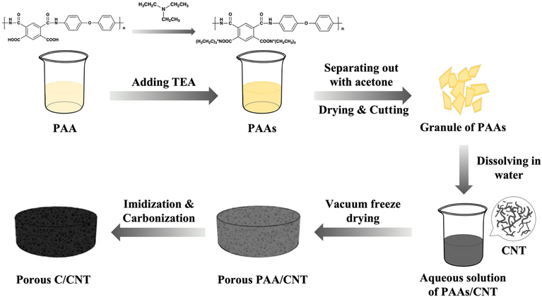 | ||
| Fig. 1 Synthesis routes for polyimide aerogel-derived amorphous porous carbon/crystalline carbon composites (PIC/rGO and PIC/CNT). | ||
Materials characterization
The thermal properties of samples were obtained by thermogravimetric analysis (TGA, PerkinElmer, heating rate: 10 °C min−1; gas flow: 50 mL min−1). The chemical structures of samples were obtained by X-ray powder diffraction(XRD, D/MAX-Ultima IV, Cu Kα, 10–80°, 10° min−1), Raman spectroscopy (LabRAM HR Evolution, 523 nm laser), Fourier transform infrared spectroscopy (FT-IR, Nicolet 6700). The morphology of synthesized materials was determined by scanning electron microscopy (SEM, Nova Nano 450). The magnetic properties were measured on a vibrating sample magnetometer (VSM, LakeShore 7404, 298 K). The electromagnetic parameters (complex permeability and permittivity) were measured on a network analyzer (N5244A PNA-X, Agilent, toroidal-shaped samples with 25 wt% of products in a paraffin wax matrix, coaxial waveguide method, frequency range: 2–18 GHz).Results and discussion
The porous PI aerogels prepared by vacuum freeze-drying were imidized, carbonized, and ground to obtain the absorbing agent PIC. The infrared spectra of PAA, PI, and PIC are shown in Fig. 2a. The characteristic O![[double bond, length as m-dash]](https://www.rsc.org/images/entities/char_e001.gif) C–NH peak in the PAA sample disappeared after it underwent a thermal imidization reaction. The double peaks at 1776 cm−1 and 1717 cm−1 in the PI sample indicate the presence of symmetric and asymmetric C
C–NH peak in the PAA sample disappeared after it underwent a thermal imidization reaction. The double peaks at 1776 cm−1 and 1717 cm−1 in the PI sample indicate the presence of symmetric and asymmetric C![[double bond, length as m-dash]](https://www.rsc.org/images/entities/char_e001.gif) O stretching vibrations of the imide group. The peaks at 1376 cm−1 and 725 cm−1 indicate C–N–C stretching vibration.33 After carbonization at 1000 °C, all the absorption peaks of PI disappeared in the IR spectrum. As shown in Fig. 2b, the sample weight did not change significantly between 100 °C and 487 °C. The temperatures for initial weight loss and the fastest weight loss rate of the sample were 487 °C and 593 °C, respectively. And the residual carbon content of the sample at 800 °C is 55.5%.
O stretching vibrations of the imide group. The peaks at 1376 cm−1 and 725 cm−1 indicate C–N–C stretching vibration.33 After carbonization at 1000 °C, all the absorption peaks of PI disappeared in the IR spectrum. As shown in Fig. 2b, the sample weight did not change significantly between 100 °C and 487 °C. The temperatures for initial weight loss and the fastest weight loss rate of the sample were 487 °C and 593 °C, respectively. And the residual carbon content of the sample at 800 °C is 55.5%.
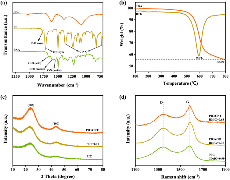 | ||
| Fig. 2 (a) FT-IR spectra of PAA, PI and PIC; (b) TGA and DTG curves of PI used in this work; (c) XRD spectra of PIC/CNT, PIC/rGO and PIC; (d) Raman spectra of PIC/CNT, PIC/rGO and PIC. | ||
The sample was characterized by XRD to further characterize its structure. As shown in Fig. 2c, the porous PI was carbonized after pyrolysis at 1000 °C. The dispersion peaks of PIC at 23.5° and 43.7° correspond to the (002) and (100) crystal planes of graphite. It shows that the carbon obtained by carbonization had an amorphous carbon structure and disordered graphite microcrystals. The dispersion peaks at 23.5° and 43.7° became sharper with the addition of CNT and rGO. It indicates an increase in the graphite microcrystal content inside the sample. The sample was further characterized by Raman spectroscopy. As shown in Fig. 2, the Raman frequency shift peaks occurred at 1350 cm−1 and 1585 cm−1. Additionally, all samples were mixtures of graphite and amorphous carbon. The D-band and G-band intensity ratios (ID/IG) of PIC, PIC/rGO, and PIC/CNT were 0.99, 0.75, and 0.63, respectively. It is further demonstrated that adding CNT or rGO significantly improved the graphitization of the samples.
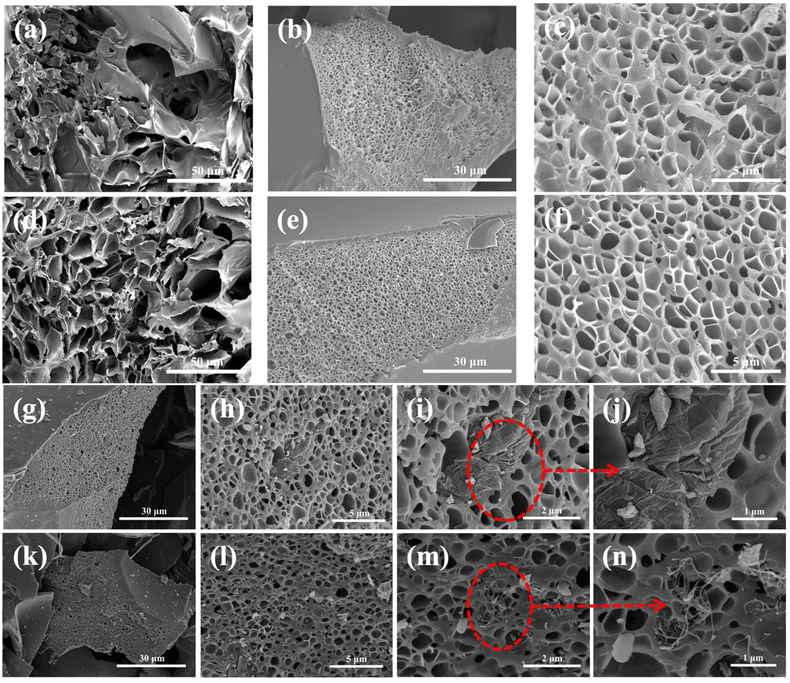
Furthermore, the pore structures of PAA, PIC, PIC/rGO, and PIC/CNT were characterized by SEM. As shown in Fig. 3a and b, water sublimation during the vacuum freeze-drying process formed obvious pores inside the PAA. The pore size was about 800–900 nm. After imidization and carbonization, the pore shrank and decreased to 500–600 nm. However, the shape of the pore remained intact, as shown in Fig. 3c and d. The reason is that the rigid structure of the polymer plays a supporting role in the polymer carbonization process, and the combination of the slow heating process makes the polymer chain “frozen” during the thermal decomposition process.34 As shown in Fig. 3g–n, the rGO and the CNTs were randomly dispersed in the PIC separately. Therefore, porous PIC, PIC/rGO, and PIC/CNT composite absorbers were successfully synthesized as expected.
The EWM absorption performance of the absorber depends on its electromagnetic parameters, which include the complex dielectric constant εr (εr = ε′ − iε′′) and complex permeability μr (μr = μ′ − iμ′′). The real parts of the dielectric constant and permeability (ε′ and μ′) represent the electromagnetic energy storage capacity of the material. However, the imaginary parts of dielectric constant and magnetic permeability (ε′′ and μ′′) represent the ability of the material to lose electromagnetic energy.35 As shown in Fig. 4a, ε′ and ε′′ of the three sample groups exhibit a strong frequency dependence. As with most carbon materials, ε′ and ε′′ of the sample decreased with an increase in the EWM frequency. The ε′ and ε′′ values of PIC were less than 12.5 and 3.8, respectively, throughout the tested EWM frequency range. However, the ε′ values of PIC/rGO and PIC/CNT were greater than 12.5 in the frequency range of 2–10 GHz, and the ε′′ values of PIC/rGO and PIC/CNT are both greater than 3.8 in the frequency range of 2–12 GHz. The μ′ and μ′′ values of the three sample groups were the same. As shown in Fig. S1a,† all μ′ and μ′′ were around 1 and 0, respectively, which indicates that the material is characterized by almost no magnetic loss.
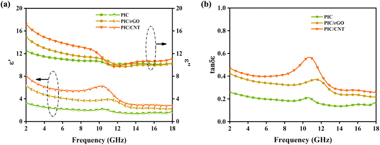 | ||
| Fig. 4 (a) Relative permittivity of PIC, PIC/rGO and PIC/CNT; (b) dielectric tangent loss of PIC, PIC/rGO and PIC/CNT. | ||
The dielectric tangential loss (tan![[thin space (1/6-em)]](https://www.rsc.org/images/entities/char_2009.gif) δε = ε′′/ε′) characterizes the dielectric loss capability of an EMW absorber. A high ε′′ and low ε′ indicate a high dielectric loss in the material.36 As shown in Fig. 4b, adding rGO and CNT increases the dielectric loss capability of the material, which is more significantly increased for PIC/CNT. Furthermore, the magnetic tangent loss (tan
δε = ε′′/ε′) characterizes the dielectric loss capability of an EMW absorber. A high ε′′ and low ε′ indicate a high dielectric loss in the material.36 As shown in Fig. 4b, adding rGO and CNT increases the dielectric loss capability of the material, which is more significantly increased for PIC/CNT. Furthermore, the magnetic tangent loss (tan![[thin space (1/6-em)]](https://www.rsc.org/images/entities/char_2009.gif) δμ = μ′′/μ′) characterizes the magnetic loss capability of the EMW absorber. As shown in Fig. S1b,† the tan
δμ = μ′′/μ′) characterizes the magnetic loss capability of the EMW absorber. As shown in Fig. S1b,† the tan![[thin space (1/6-em)]](https://www.rsc.org/images/entities/char_2009.gif) δμ of the three sample sets is around 0, which further proves the negligible magnetic loss capability of the material. In summary, adding rGO or CNT enhances the electromagnetic parameters and improves the dielectric loss characteristics of the material.
δμ of the three sample sets is around 0, which further proves the negligible magnetic loss capability of the material. In summary, adding rGO or CNT enhances the electromagnetic parameters and improves the dielectric loss characteristics of the material.
The Cole–Cole diagrams describe the dielectric polarization properties of the material. As shown in Fig. S2,† there is only one Debye pole relaxation process in the three sample sets. However, the radii of PIC/rGO and PIC/CNT arcs were significantly larger than those of PIC. Furthermore, this indicates that PIC/rGO and PIC/CNT have stronger dipole relaxation processes, which is the reason they have higher dielectric losses than PIC.
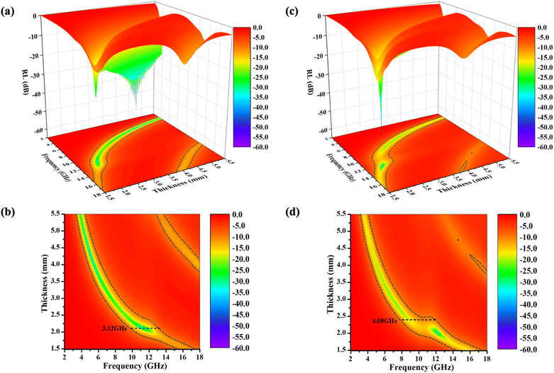
Based on the electromagnetic parameters obtained from the tests, transmission line theory, and eqn (1) and (2), the reflection loss (RL) of the PIC, PIC/rGO, and PIC/CNT absorbers were calculated. Additionally, the results are shown in Fig. 5.
RL = 20![[thin space (1/6-em)]](https://www.rsc.org/images/entities/char_2009.gif) lg|(Zin − Z0)/(Zin + Z0)| lg|(Zin − Z0)/(Zin + Z0)|
| (1) |
 | (2) |
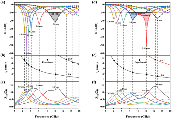
As shown in Fig. 5(a) and (b), the PIC/rGO samples exhibited strong EMW attenuation characteristics. The minimum reflection loss (RLmin) of 4.96 GHz EWMs in PIC/rGO was −57.22 dB at 4.36 mm thickness, which exceeds 99.999% EMW absorption. The effective attenuation bandwidth (EABW, greater than 90% EMW absorption, RL less than −10 dB) of PIC/rGO is 3.12 GHz (10.40–13.52 GHz) at 2.0 mm thickness. Additionally, for PIC/rGO sample thicknesses in the 1.5–5.5 mm range, the RLmin was below −10 dB for each thickness. As shown in Fig. 5(c) and (d), the PIC/CNT samples exhibit strong EMW attenuation characteristics. The RLmin of PIC/CNT at 12.16 GHz EWM is −51.2 dB, and the EABW is 3.96 GHz (9.52–13.44 GHz) at 2.02 mm thickness. The EABW of PIC/CNT is 4.08 GHz (7.84–11.92 GHz) at 2.4 mm thickness. Additionally, for PIC/CNT sample thicknesses in the 1.5–5.5 mm range, the RLmin was below −10 dB for each thickness. As shown in Fig. S3,† the absorption performances of PIC/rGO and PIC/CNT were significantly better than that of PIC. Therefore, adding 0.5% rGO or CNT can effectively improve the wave absorption performance of the material.
The EWM properties of the three sample sets were further investigated using a single-layer uniform flat plate absorber model. As shown in Fig. 7, the incident EMW energy effect on the absorber (E0) is divided into three parts: EMW energy reflected at the air–absorber interface (E1), EMW energy lost by attenuation inside the absorber (E2), and EMW energy reflected at the absorber–metal substrate interface (E3). Furthermore, a high-performance absorbing material should have three properties: impedance matching, attenuation characteristics, and interference cancellation characteristics.37,38
First, E1 should be as small as possible for EWMs to enter the material smoothly. Eqn (3) shows that if the impedance characteristic parameter Z value of the material (Z = Zin/Z0) is close to 1 (dielectric wave impedance Zin is close to free space wave impedance Z0), the reflection at the air–absorber interface is minimal. As shown in Fig. 6c and f, the Z values of PIC/rGO and PIC/CNT absorbers with different thicknesses were close to 1 at the PL peak frequency. As shown in Fig. S4,† the PIC absorber exhibited better impedance matching at larger thicknesses. Additionally, for PIC, PIC/rGO, and PIC/CNT absorbers, the surface of the porous structure is closer to the free space to obtain a good matching condition.39,40
 | (3) |
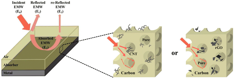 | ||
| Fig. 7 Model of single-layer homogeneous electromagnetic wave absorber with PIC/rGO or PIC/CNT as absorbers. | ||
Second, the absorber should have excellent attenuation characteristics internally, i.e., the E2 value should be large. The attenuation characteristics of the samples have been described earlier in this study. Additionally, EMW is mainly attenuated by dielectric loss. PIC/rGO and PIC/CNT have significantly better attenuation capabilities than PIC. Furthermore, this is due to the increased crystallized carbon content in the material on adding rGO or CNT, which increases the dielectric loss capability.
Finally, the loss of EWMs also depends on the interference of the EWMs. Therefore, E1 and E3 should be made in opposite phases to achieve interference cancellation to obtain a stronger reflection loss of the material.41–43 The matched thickness of the sample was calculated by eqn (4), according to the quarter-wavelength extinction theory. As shown in Fig. 6b and e, the thicknesses corresponding to the RL peaks of PIC/rGO and PIC/CNT samples were located around the λ/4 and 3λ/4 curves, respectively. Therefore, the PIC/rGO and PIC/CNT samples conform to the quarter-wavelength wave elimination theory to help with the EMW attenuation.
 | (4) |
Combining the above results shows that PIC/rGO and PIC/CNT have excellent wave absorption performance due to their special structural design. A lower E1 value allows EMW to enter the material smoothly. Additionally, suitable rGO or CNT additions yielded high E2 values. Since it is consistent with the quarter-wavelength extinction theory, E1 and E3 values cancel out. Furthermore, the porous structure increases the path of EWM propagation.
Table 1 lists some recently developed carbon-based EMW absorbers. Compared with other materials, PIC/rGO and PIC/CNT obtain excellent reflection loss with only dielectric loss. In addition, the effective absorption bandwidth of PIC/rGO and PIC/CNT reaches over 3 GHz at a thin thickness, and PIC/CNT has an effective absorption bandwidth of 4 GHz. More importantly, PIC/rGO and PIC/CNT samples can achieve broad absorption at lower fill rates (25%). PIC/rGO and PIC/CNT meet the requirements of lightweight, strong absorption, wider frequency band and easy synthesis for efficiency electromagnetic wave absorbing materials without introducing magnetic loss. Therefore, PIC/rGO and PIC/CNT have greater potential for applications in high-performance EMW absorbing materials.
| Absorber sample | EABW | Filler loading | RLmin |
|---|---|---|---|
| Magnetic carbon foam44 | 3.30 GHz (4.70 mm) | 30.0 wt% | −43.60 dB (4.70 mm) |
| SiC/C foam45 | 10.84 GHz (3.75 mm) | 50.0 wt% | −51.58 dB (3.60 mm) |
| Honeycombed-like carbon aerogel46 | 4.02 GHz (1.50 mm) | 30.0 wt% | −45.02 dB (1.50 mm) |
| SiC@graphene47 | 2.64 GHz (2.50 mm) | 15.0 wt% | −16.20 dB (2.50 mm) |
| MoC1−x/C38 | 5.36 GHz (2.00 mm) | 20.0 wt% | −50.55 dB (1.80 mm) |
| Ni/graphene composite foam48 | 4.91 GHz (4.50 mm) | 15.0 wt% | −53.11 dB (4.50 mm) |
| PIC/Co-1000 (ref. 33) | 4.10 GHz (1.40 mm) | 25.0 wt% | −40.22 dB (5.30 mm) |
| Ni/C-20 (ref. 49) | 5.10 GHz (1.80 mm) | 30.0 wt% | −57.3 dB (1.80 mm) |
| NiCo/CoNiO2@C S-2 (ref. 50) | 6.32 GHz (2.40 mm) | 25.0 wt% | −23.0 dB (2.40 mm) |
| PIC/rGO (this work) | 3.12 GHz (2.00 mm) | 25.0 wt% | −57.22 dB (4.36 mm) |
| PIC/CNT (this work) | 3.96 GHz (2.02 mm) | 25.0 wt% | −51.2 dB (2.02 mm) |
Conclusions
In this study, PIC/rGO and PIC/CNT were prepared by vacuum freeze-drying and high-temperature pyrolysis. The porous structure enriched the interfacial polarization and improved the impedance-matching conditions. Adding appropriate amounts of rGO and CNT improved the electromagnetic parameters of the materials and increased the dielectric losses. The RLmin of PIC/rGO was −57.22 dB at 4.96 GHz at 4.36 mm thickness. The EABW for PIC/rGO was 3.12 GHz at 2.0 mm thickness. The RLmin of PIC/CNT was −51.2 dB at 12.16 GHz, and EABW was 3.96 GHz at 2.02 mm thickness. The EABW was 4.08 GHz at 2.4 mm PIC/CNT thickness. Therefore, PIC/rGO and PIC/CNT designed in this study have simple preparation methods and excellent EMW absorption performances, which have great application potential in high-performance absorbing materials.Conflicts of interest
There are no conflicts to declare.Acknowledgements
The authors gratefully acknowledge the National Key R&D Program of China (No. 2020YFB0408100), Guangdong Innovative and Entrepreneurial Research Team Program (No. 2016ZT06C412), National Natural Science Foundation of China (NSFC; No. U20A20340).Notes and references
- X. Zeng, X. Cheng, R. Yu and G. D. Stucky, Carbon, 2020, 168, 606–623 CrossRef CAS.
- P. Hu, S. Dong, X. Li, J. Chen, X. Zhang, P. Hu and S. Zhang, J. Mater. Chem. C, 2019, 7, 9219–9228 RSC.
- W. T. Cao, F. F. Chen, Y. J. Zhu, Y. G. Zhang, Y. Y. Jiang, M. G. Ma and F. Chen, ACS Nano, 2018, 12, 4583–4593 CrossRef CAS PubMed.
- X. Li, D. Du, C. Wang, H. Wang and Z. Xu, J. Mater. Chem. C, 2018, 6, 558–567 RSC.
- J. Fang, P. Li, Y. Liu and Y. Min, J. Mater. Chem. C, 2021, 9, 2474–2482 RSC.
- F. Wang, Y. Sun, D. Li, B. Zhong, Z. Wu, S. Zuo, D. Yan, R. Zhuo, J. Feng and P. Yan, Carbon, 2018, 134, 264–273 CrossRef CAS.
- Q. Zeng, L. Wang, X. Li, W. You, J. Zhang, X. Liu, M. Wang and R. Che, Appl. Surf. Sci., 2021, 538, 148051–148059 CrossRef CAS.
- X. Li, P. Liu and J. Li, Colloids Surf., A, 2022, 644, 128863–1128872 CrossRef CAS.
- Z. Jia, X. Zhang, Z. Gu and G. Wu, Adv. Compos. Hybrid Mater., 2022, 6, 28–39 CrossRef.
- B. Zhao, X. Guo, W. Zhao, J. Deng, G. Shao, B. Fan, Z. Bai and R. Zhang, ACS Appl. Mater. Interfaces, 2016, 8, 28917–28925 CrossRef CAS PubMed.
- M. Ma, W. Li, Z. Tong, W. Huang, R. Wang, P. Lyu, Y. Ma, G. Wu, Q. Yan, P. Li and X. Yao, J. Alloys Compd., 2020, 843, 155199–155208 CrossRef CAS.
- G. Wu, H. Zhang, X. Luo, L. Yang and H. Lv, J. Colloid Interface Sci., 2019, 536, 548–555 CrossRef CAS PubMed.
- W. Wei, X. Yue, Y. Zhou, Z. Chen, J. Fang, C. Gao and Z. Jiang, Phys. Chem. Chem. Phys., 2013, 15, 21043–21050 RSC.
- Y. Liu, Y. Liu and X. Zhao, J. Text. Inst., 2017, 109, 106–112 CrossRef.
- X. Ye, Z. Chen, M. Li, T. Wang, J. Zhang, C. Wu, Q. Zhou, H. Liu and S. Cui, Composites, Part B, 2019, 178, 107479–107486 CrossRef CAS.
- W. Duan, X. Yin, F. Cao, Y. Jia, Y. Xie, P. Greil and N. Travitzky, Mater. Lett., 2015, 159, 257–260 CrossRef CAS.
- Y. Wang, F. Luo, W. Zhou and D. Zhu, Ceram. Int., 2014, 40, 10749–10754 CrossRef CAS.
- H. Yuan, F. Yan, C. Li, C. Zhu, X. Zhang and Y. Chen, ACS Appl. Mater. Interfaces, 2018, 10, 1399–1407 CrossRef CAS PubMed.
- H. Liang, H. Xing, M. Qin and H. Wu, Composites, Part A, 2020, 135, 105959–105970 CrossRef CAS.
- K. K. Gupta, S. M. Abbas and A. C. Abhyankar, J. Ind. Text., 2015, 46, 510–529 CrossRef.
- L. Kong, X. Yin, H. Xu, X. Yuan, T. Wang, Z. Xu, J. Huang, R. Yang and H. Fan, Carbon, 2019, 145, 61–66 CrossRef CAS.
- T. Zhao, C. Hou, H. Zhang, R. Zhu, S. She, J. Wang, T. Li, Z. Liu and B. Wei, Sci. Rep., 2014, 4, 5619–5625 CrossRef CAS PubMed.
- S. Guo, Y. Zhang, J. Chen, Y. Wu, J. Cao, S. Tang and G. Ji, Inorg. Chem. Front., 2022, 9, 3244–3250 RSC.
- X. Chen, H. Liu, D. Hu, H. Liu and W. Ma, Ceram. Int., 2021, 47, 23749–23761 CrossRef CAS.
- D. Wang, J. Jin, Y. Guo, H. Liu, Z. Guo, C. Liu and C. Shen, Carbon, 2023, 202, 464–474 CrossRef CAS.
- X. Ye, Z. Chen, S. Ai, B. Hou, J. Zhang, X. Liang, Q. Zhou, H. Liu and S. Cui, J. Adv. Ceram., 2019, 8, 479–488 CrossRef CAS.
- W.-C. Li, C.-S. Li, L.-H. Lin, Y. Wang and J.-S. Zhang, Mater. Res. Express, 2018, 5, 115802–115815 CrossRef.
- D. Fan, B. Wei, R. Wu, J. Zhou and C. Zhou, J. Mater. Sci., 2021, 56, 6830–6844 CrossRef CAS.
- Y. Zhan, L. Xia, H. Yang, N. Zhou, G. Ma, T. Zhang, X. Huang, L. Xiong, C. Qin and W. Guangwu, Carbon, 2021, 175, 101–111 CrossRef CAS.
- M. Inagaki, T. Ibuki and T. Takeichi, J. Appl. Polym. Sci., 1992, 44, 521–525 CrossRef CAS.
- T. Takeichi, H. Takenoshita, S. Ogura and M. Inagaki, J. Appl. Polym. Sci., 2010, 54, 361–365 CrossRef.
- K. M. Inagaki, Carbon, 1992, 3, 333–337 Search PubMed.
- W. Yu, Y. Min, J. Fang, X. Lu, Z. Wang and L. Jian, RSC Adv., 2022, 12, 29070–29077 RSC.
- T. Takeichi, Y. Endo, Y. Kaburagi, Y. Hishiyama and M. Inagaki, J. Appl. Polym. Sci., 2015, 68, 1613–1620 CrossRef.
- M. González, J. Baselga and J. Pozuelo, J. Mater. Chem. C, 2016, 4, 1–9 RSC.
- R. Zhang, J. Qiao, X. Zhang, Y. Yang, S. Zheng, B. Li, W. Liu, J. Liu and Z. Zeng, Mater. Chem. Phys., 2022, 289, 126437–126445 CrossRef CAS.
- Z. Liu, G. Bai, Y. Huang, F. Li, Y. Ma, T. Guo, X. He, X. Lin, H. Gao and Y. Chen, J. Phys. Chem. C, 2007, 111, 13696–13700 CrossRef CAS.
- T. Zhao, Z. Jia, Y. Zhang and G. Wu, Small, 2022, 19, 2206323–2206335 CrossRef PubMed.
- Q. Li, J. Liu, Y. Zhao, X. Zhao, W. You, X. Li and R. Che, ACS Appl. Mater. Interfaces, 2018, 10, 27540–27547 CrossRef CAS PubMed.
- Y. Liu, X. Zhou, Z. Jia, H. Wu and G. Wu, Adv. Funct. Mater., 2022, 32, 2204499–2204509 CrossRef CAS.
- J. Xiang, J. Li, X. Zhang, Q. Ye, J. Xu and X. Shen, J. Mater. Chem. A, 2014, 2, 16905–16914 RSC.
- S. Zhang, Z. Jia, Y. Zhang and G. Wu, Nano Res., 2022, 16, 3395–3407 CrossRef.
- C. Wang, Y. Liu, Z. Jia, W. Zhao and G. Wu, Nano-Micro Lett., 2022, 15, 13–28 CrossRef.
- G. Gou, F. Meng, H. Wang, M. Jiang, W. Wei and Z. Zhou, Nano Res., 2019, 12, 1423–1429 CrossRef CAS.
- X. Ye, Z. Chen, M. Li, T. Wang, C. Wu, J. Zhang, Q. Zhou, H. Liu and S. Cui, ACS Sustainable Chem. Eng., 2019, 7, 18395–18404 CrossRef CAS.
- J. Xu, X. Zhang, Z. Zhao, H. Hu, B. Li, C. Zhu, X. Zhang and Y. Chen, Small, 2021, 17, 2102032–2102045 CrossRef CAS.
- D. Zhao, X. Yuan, B. Li, F. Jiang, Y. Liu, J. Zhang, C. Niu and S. Guo, Chem. Phys., 2020, 529, 110574–110583 CrossRef CAS.
- Q. Liu, X. He, C. Yi, D. Sun, J. Chen, D. Wang, K. Liu and M. Li, Composites, Part B, 2020, 182, 107614–107625 CrossRef CAS.
- Y. Qiu, Y. Lin, H. Yang, L. Wang, M. Wang and B. Wen, Chem. Eng. J., 2020, 383, 123207–123215 CrossRef CAS.
- X. Zhou, Z. Jia, A. Feng, S. Qu, X. Wang, X. Liu, B. Wang and G. Wu, J. Colloid Interface Sci., 2020, 575, 130–139 CrossRef CAS PubMed.
Footnote |
| † Electronic supplementary information (ESI) available. See DOI: https://doi.org/10.1039/d3ra00155e |
| This journal is © The Royal Society of Chemistry 2023 |

