 Open Access Article
Thermogravimetric and spectroscopic analyses along with the kinetic modeling of the pyrolysis of phosphate tailings†
Xue-Mei Yuana,
Hui-Juan Xiea,
Deng-Pan Nie *a,
Yu Zhang*b,
Lan Zhouac,
Yi-Yi Wua and
Zhu Wena
aSchool of Chemical Engineering, Guizhou Minzu University, Guiyang, China. E-mail: ndpz@sina.com; Tel: +86 13339619988
bCollege of Chemistry and Chemical Engineering, Guizhou University, Guiyang, China. E-mail: 342114915@qq.com; Tel: +86 13368515556
cSchool of Chemistry and Chemical Engineering, South China University of Technology, Guangzhou, China
First published on 5th June 2023
Abstract
The present study aimed to understand the pyrolysis characteristics of phosphorus tailings and promote the resource utilization of phosphorus tailings. Thermogravimetry was combined with Fourier transform infrared spectroscopy-Raman spectroscopy-mass spectrometry (TG-FTIR-RS-MS) and kinetic models to investigate the possible reaction mechanisms during the pyrolysis of phosphorus tailings and the changes in the release characteristics of pyrolysis volatiles. The results showed that the pyrolysis process occurred in three different stages. First, small amounts of adsorbed water were removed, and organic matter in the tailings was decomposed. Second, CaMg(CO3)2 underwent thermal decomposition to produce CaCO3, MgO, and CO2. Third, CaCO3 further decomposed into CaO and CO2. Similarly, the pyrolysis kinetics were divided into three intervals based on the differences in their activation energy values. The pyrolysis reaction mechanism functions were two-dimensional diffusion (Valensi model), nucleation and growth (Avrami–Erofeev, n = 1/2), and nucleation and growth (Avrami–Erofeev, n = 1/4). The gases released during the pyrolysis of phosphate tailings were mainly CO2, F2, and HF.
1. Introduction
The global distribution of phosphorus ore is uneven, mainly concentrated in Morocco, China, and Egypt. Morocco is the region with the most abundant phosphate ore resources in the world, followed by China. Due to the rapid expansion of China's phosphate fertilizer production capacity and the increasing demand for phosphate chemical products, the long-term and intensive development and utilization of phosphate ore resources has been a major research focus in China.1 Phosphate tailings are a type of solid waste that is generated during the concentration of phosphate ores through various flotation processes, such as positive flotation, reverse flotation, positive-reverse flotation, and others.2,3 Typically, 0.44 tons of phosphate tailings are produced for each ton of phosphate concentrate produced. According to statistics, the total stockpile of tailings in China is eight billion tons. However, due to the low comprehensive utilization rate, a large proportion of phosphate tailings is mainly disposed of by stockpiling at a relatively low cost,4 which is a waste of resources and may also cause serious environmental pollution.5–7Gnandi et al.8 have found that phosphate tailings contain high levels of potentially toxic metals such as Cr, Cd, Cu, V, Ni, U, and Zn. These heavy metals can pollute soil and surface groundwater,9 leading to potential health risks for people living downstream of tailing-related facilities who may consume polluted drinking water and food chains with increased concentrations of heavy metals.10,11 Furthermore, the failure of tailings storage facilities may lead to more serious environmental disasters.12–14
Phosphate tailings consist mainly of carbonate minerals, quartz (SiO2), and fluorapatite (Ca5[PO4]3F), with chemical components that primarily include MgO, CaO, and P2O5, as well as small amounts of SiO2, Fe2O3, and Al2O3.15 They also contain a significant proportion of silicon and calcium components, which make them ideal for utilization in the production of calcium magnesium aluminosilicate refractories, ceramsite,16 or cement.17,18 However, the high-temperature calcination required for these processes necessitates the careful analysis of the high-temperature pyrolysis characteristics of phosphate tailings to improve the design of product-processing steps. Therefore, further research is needed to optimize the utilization of phosphate tailings and develop more sustainable approaches to their management.
The high-temperature decomposition process of phosphate tailings is a complex reaction system involving multiple components and phases.19–21 However, the pyrolysis kinetics, reaction mechanism, and gas evolution process of phosphate tailings remain uncertain. Most of the current research focuses on the calcination process to prepare relevant products from the tailings.16
The present study aimed to evaluate the pyrolysis behavior and kinetic parameters of phosphate tailings using thermogravimetry (TG) combined with the Flynn–Wall–Ozawa (FWO) and Kissinger–Akahira–Sunose (KAS) multiple heating rate methods. We also clarify the possible reaction mechanism of the pyrolysis process using the Criado method22,23 (integral principal curve method). Additionally, we used Fourier transform infrared spectroscopy-Raman spectroscopy-mass spectrometry (TG-FTIR-RS-MS) combined technology to investigate phosphate tailings pyrolysis and the distribution of released volatiles with temperature change, providing a theoretical model for the recycling of phosphate tailings.
Overall, this study provides new and important insights into the pyrolysis behavior and kinetic parameters of phosphate tailings, which could be used to optimize the utilization of this waste material and develop sustainable approaches for its management.
2. Experimental
2.1 Materials
Phosphate tailings obtained from Guizhou Phosphate Chemical Group Co., Ltd were dried, mixed, and ground to a particle size of less than 200 mesh for further experimentations. Table 1 presents the main components of the phosphate tailings used in this study.| Chemical composition | CaO | MgO | P2O5 | SiO2 | F | SO3 | Al2O3 | |
| Phosphate tailings | 60.697 | 22.535 | 9.230 | 3.357 | 1.476 | 1.148 | 0.543 | |
| Chemical Composition | Fe2O3 | Na2O | K2O | MnO | TiO2 | Cl | SrO | ZnO |
| Phosphate tailings | 0.527 | 0.171 | 0.108 | 0.090 | 0.044 | 0.038 | 0.021 | 0.014 |
2.2 Experimental procedure
The phosphorus tailings were ground to a particle size of less than 200 mesh. Approximately 4–5 mg of the powder was loaded sample into a pyrolysis tube and heated to 1000 °C in a high-purity N2 atmosphere at different heating rates. Approximately 4–5 g of phosphorus tailings samples were calcinated after treatment in a muffle furnace at different temperatures to obtain experimental samples at different calcination temperatures.To determine the chemical reactions that occurred during the calcination process, we used the thermodynamic calculation software HSC Chemistry 8.0. The thermodynamic conditions for spontaneous reactions are discussed below.
2.3 Characterization
A TG analyzer (model: TG 209 F1 Libra) produced by NETZSCH GmbH (Selb, Germany) and FITR (model: iS50) of Thermo Fisher Scientific (Waltham, MA, USA) were used to perform thermal analysis and measure the TG characteristics and infrared (IR) curve of the samples. The test parameters were as follows: 20 mg of a sample in a nitrogen atmosphere was heated from 35 °C to 1100 °C, with heating rates of 10, 20, 30, and 40 °C min−1; the sampling parameter resolution of the Fourier Transform Infrared Spectrometer was 4 cm−1; and the wavenumber range was 4000–400 cm−1. An X-ray diffractometer (model: Panaco Empyrean) was used to analyze the phase composition of calcined phosphorite. The test conditions were: voltage of 40 kV, current of 40 mA, continuous scanning, scanning range of 10–80°, and scanning speed of 2° min−1. The chemical composition of the calcined phosphate tailings was analyzed using an X-ray fluorescence (XRF) analyzer. A TG analyzer and MS (PE TGA8000-FRONTIER-SQ8) were used to detect the distribution of volatile matter and gases with reaction temperature from the pyrolysis. The detection conditions were: He gas 99.999% atmosphere and a carrier gas flow rate of 20 mL min−1.2.4 Dynamic theoretical analysis
The basic rate equation was expressed as eqn (1):
 | (1) |
The conversion rate (α) was defined in eqn (2):
 | (2) |
The rate constant k was described by the Arrhenius eqn (3):
 | (3) |
Eqn (4) was obtained from eqn (1) and (3).
 | (4) |
 | (5) |
 | (6) |
At a constant heating rate, eqn (7) can be obtained by integrating eqn (6):
 | (7) |
For the Flynn–Wall–Ozawa (FWO) method, in a non-isothermal process with a constant heating rate, Doyle's approximate formula is used: p(xα) ≅ exp(−2.315 + 0.4567x), where x = Ea/RTα, Tα is the temperature at a specific conversion rate, resulting in the FWO formula shown in eqn (8).
 | (8) |
For the Kissinger–Akahira–Sunose (KAS) method, Murray and White's approximations were used: p(xα) ≅ ex/x2, where x = Ea/RTα. The resultant KAS formula obtained is shown in eqn (9).
 | (9) |
The average value of Ea in each conversion range obtained by using the FWO and KAS methods in eqn (7) was substituted into the empirical eqn (10) to solve the p(xα) function value corresponding to α.
 | (10) |
Taking the selected α interval value α1 into eqn (7) for transformation:
 | (11) |
Then, eqn (7) was divided by eqn (11) to obtain the integral principal graph equation:
 | (12) |
3. Results and discussion
3.1 Thermal decomposition process analysis
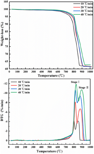
The results of differential TG-DTG pyrolysis of phosphate tailings are illustrated in Fig. 1, which shows similar trends at different heating rates. When the temperature of the TG line is below 600 °C, the curve line undergoes a slow weight loss phenomenon, which is caused by the removal of a small amount of adsorbed water from the tailings and the decomposition of organic matter. In the temperature range of 600–950 °C, a pronounced weight loss of phosphorus tailings is evident at an average rate of approximately 37%. Preliminary analysis demonstrated that this phenomenon was attributed to the decomposition of carbonate in the sample. According to the change in the TG curve slope, the entire pyrolysis process can be divided into two stages: two characteristic weight loss-rate peaks of the DTG curve at 614–817 °C and 817–879 °C, respectively. An increase in the heating rate from 10 °C min−1 to 40 °C min−1 shifts each weight loss-rate peak to the right because, in the same time interval and temperature range, a faster heating rate will lead to a shorter reaction time, thereby requiring a higher temperature for the sample decomposition.The multipeak Gaussian fitting method was used to fit the DTG curves at different heating rates. The results are shown in Fig. S1,† and the relevant parameters of the fitting curve are listed in Table 2. These results show that the temperature range of peak A spans from 567.5 °C to 855.9 °C, and the weight loss rate is between 18.06% and 18.36%, corresponding to the thermal decomposition of CaMg(CO3)2 into CaCO3, MgO, and CO2. The temperature range of peak B spans from 781.3 °C to 954.4 °C, and the weight loss rate is between 18.45% and 19.26%, corresponding to the thermal decomposition of CaCO3 into CaO and CO.
| Heating rates | Components | Tc (°C) | Tr (°C) | W (°C) | S (%/°C) | Hc (%/°C) | R2 |
|---|---|---|---|---|---|---|---|
| a Tc: highest point temperature of the peak; Tr: temperature range of the peak; W, half-width of the peak; S, peak area; Hc, peak height; R2, fitting degree of the peak. | |||||||
| 10 °C min−1 | Peak A | 799.1879 | 614–817.1 | 7.8082 | 26.1669 | −3.88596 | 0.9727 |
| Peak B | 846.73391 | 794.2–878.9 | 35.99134 | 35.99137 | −3.99951 | ||
| 20 °C min−1 | Peak A | 815.74717 | 567.5–838.3 | 18.52286 | 28.77793 | −7.45791 | 0.9861 |
| Peak B | 874.25611 | 801.5–925.4 | 48.44924 | 48.44929 | −6.61369 | ||
| 30 °C min−1 | Peak A | 817.05945 | 588.9–840.4 | 36.46049 | 36.46052 | −9.0951 | 0.99 |
| Peak B | 872.95355 | 781.3–931.4 | 58.68327 | 58.68332 | −9.53543 | ||
| 40 °C min−1 | Peak A | 826.58088 | 588.9–855.9 | 47.60507 | 47.83188 | −10.82946 | 0.9929 |
| Peak B | 894.88659 | 798.3–954.4 | 62.92263 | 62.92269 | −11.03032 | ||
3.2 Material composition
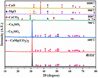
The X-ray diffraction (XRD) patterns of the phosphate tailings calcined at different temperatures (Fig. 2) demonstrate that the main component of the tailings was CaMg(CO3)2. When the temperature was below 600 °C, the sample phase was still dominated by CaMg(CO3)2, indicating the removal of a small amount of adsorbed water and the decomposition of organic matter, which corresponds to stage 1 of pyrolysis. With the gradual increase in temperature, the characteristic peak of CaMg(CO3)2 in the sample disappeared after calcination at 800 °C, and the characteristic peaks of CaCO3 and MgO appeared, indicating the thermal decomposition of CaMg(CO3)2 into CaCO3, MgO, and CO2, which corresponded to stage 2. After calcination at 900 °C and 1000 °C, the characteristic peak of CaCO3 in the sample disappeared, and the characteristic peak of CaO was observed because of the complete decomposition of CaCO3, which corresponded to stage 3. Moreover, the characteristic peaks of Ca2SiO4 and Ca3SiO5 were observed, possibly attributed to phosphate tailings containing a small number of low-melting-point phases (Na2O, K2O, and Fe2O3), which reduces the melting point of the system and promotes the reaction of CaO and SiO2, generating small amounts of Ca2SiO4 and Ca3SiO5.The composition of the phosphate tailings is complex. By combining the XRD results in Fig. 2 with the XRF results, it can be inferred that the solid-state reactions that may occur in the range of 600–1000 °C (Table S2†25,26) mainly undergo a decomposition reaction of CaMg(CO3)2, CaCO3, and H2SiF6. The relationship between the Gibbs free energy (ΔG) of each reaction and temperature is shown in Fig. 3. The analysis revealed that the decomposition of CaMg(CO3)2 increases with a corresponding increase in calcination temperature. At 800 °C, CaMg(CO3)2 tended to decompose, whereas CaCO3 and MgO had a greater tendency to form. At 900 °C, CaCO3 began to decompose, and CaO had a greater tendency to form. At T > 200 °C, H2SiF6 started to decompose, and HF had a greater tendency to form. The trend of chemical reactions among the phases in the tailings to form new phases was also observed. Reactions (1), (2), (4), (7), (8), and (9) generated substances such as CaCO3, MgO, CaO, H2SiF6, HF, Ca2SiO4, and Ca3SiO5 when ΔG <0 at 1000 °C. The theoretical analysis was consistent with the XRD results of the calcined phosphate tailing samples at different temperatures, as shown in Fig. 2.
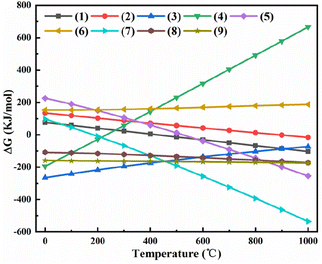 | ||
| Fig. 3 Relation between Gibbs free energy of each reaction and temperate in the phosphate tailings system. | ||
3.3 Pyrolysis kinetics analysis
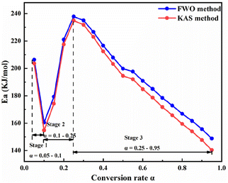
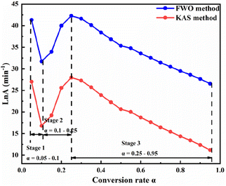
To analyze the reaction mechanism of the pyrolysis of phosphate tailings and facilitate the selection of the reaction mechanism for future use, the FWO and KAS methods were used to calculate the non-isothermal diagram of the tailings at different heating rates. Fig. 4 shows the non-isothermal diagram of pre-exponential factor ln(β) versus 1/T calculated using the FWO equation, and Fig. 5 shows the non-isothermal diagram of ln(β/T2) versus 1/T calculated using the KAS equation. The linear correlation coefficients of the two models were R2 = 0.9466–0.9951 and R2 = 0.9347–0.9934, respectively, and the fit was almost ideal. Therefore, the corresponding Ea and ln![[thin space (1/6-em)]](https://www.rsc.org/images/entities/char_2009.gif) A at different α can be calculated using the slope and intercept of each line in the figure. The results are presented in Table 3, Fig. 6 and 7.
A at different α can be calculated using the slope and intercept of each line in the figure. The results are presented in Table 3, Fig. 6 and 7.
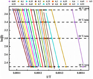 | ||
| Fig. 4 Arrhenius chart for calculating conversion rates of phosphate tailings by Flynn–Wall–Ozawa method. | ||
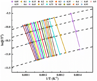 | ||
| Fig. 5 Arrhenius chart for calculating different conversion rates of phosphate tailings by Kissinger–Akahira–Sunose method. | ||
| Conversion | Ozawa–Flynn–Wall method | Kissinger–Akahira–Sunose (KAS) | ||||
|---|---|---|---|---|---|---|
| α | ln![[thin space (1/6-em)]](https://www.rsc.org/images/entities/char_2009.gif) A A |
Ea | R2 | ln![[thin space (1/6-em)]](https://www.rsc.org/images/entities/char_2009.gif) A A |
Ea | R2 |
| 0.05 | 41.33 | 206.333 | 0.9684 | 27.00 | 203.577 | 0.9655 |
| 0.1 | 31.71 | 160.455 | 0.9903 | 16.78 | 154.798 | 0.9891 |
| 0.15 | 33.97 | 179.352 | 0.9880 | 19.21 | 174.278 | 0.9871 |
| 0.2 | 40.00 | 221.064 | 0.9728 | 25.58 | 217.536 | 0.9688 |
| 0.25 | 42.29 | 237.858 | 0.9822 | 27.98 | 234.904 | 0.9790 |
| 0.3 | 41.63 | 235.044 | 0.9865 | 27.29 | 231.861 | 0.9836 |
| 0.35 | 40.14 | 226.628 | 0.9901 | 25.73 | 223.006 | 0.9877 |
| 0.4 | 38.42 | 216.607 | 0.9941 | 23.91 | 212.464 | 0.9922 |
| 0.45 | 36.86 | 207.874 | 0.9951 | 22.26 | 203.227 | 0.9934 |
| 0.5 | 35.34 | 199.789 | 0.9736 | 20.63 | 194.531 | 0.9675 |
| 0.55 | 34.77 | 197.687 | 0.9536 | 20.01 | 192.120 | 0.9438 |
| 0.6 | 33.56 | 190.843 | 0.9466 | 18.72 | 184.845 | 0.9352 |
| 0.65 | 32.54 | 185.034 | 0.9469 | 17.63 | 178.693 | 0.9351 |
| 0.7 | 31.43 | 178.466 | 0.9469 | 16.44 | 171.742 | 0.9347 |
| 0.75 | 30.48 | 172.855 | 0.9505 | 15.42 | 165.814 | 0.9385 |
| 0.8 | 29.49 | 166.865 | 0.9512 | 14.35 | 159.479 | 0.9390 |
| 0.85 | 28.62 | 161.673 | 0.9537 | 13.41 | 153.975 | 0.9415 |
| 0.9 | 27.65 | 155.714 | 0.9587 | 12.36 | 147.673 | 0.9471 |
| 0.95 | 26.56 | 148.838 | 0.9638 | 11.17 | 140.415 | 0.9529 |
Fig. 6 and 7 show that the changing trend of Ea calculated using the FWO and KAS methods and ln![[thin space (1/6-em)]](https://www.rsc.org/images/entities/char_2009.gif) A are consistent with α. Table 3 shows that, in a particular conversion rate range, the Ea value calculated using the FWO method was slightly higher than that calculated using the KAS method, with the difference ranging from 2.756–8.423 kJ mol−1. The difference between the Ea calculated by the two methods was insignificant, and a single kinetic mechanism could describe the pyrolysis process. According to Fig. 6 and 7, the pyrolysis kinetics of phosphate tailings could be divided into three stages according to changes in Ea and ln
A are consistent with α. Table 3 shows that, in a particular conversion rate range, the Ea value calculated using the FWO method was slightly higher than that calculated using the KAS method, with the difference ranging from 2.756–8.423 kJ mol−1. The difference between the Ea calculated by the two methods was insignificant, and a single kinetic mechanism could describe the pyrolysis process. According to Fig. 6 and 7, the pyrolysis kinetics of phosphate tailings could be divided into three stages according to changes in Ea and ln![[thin space (1/6-em)]](https://www.rsc.org/images/entities/char_2009.gif) A with α. Stage 1 (temperature lower than 600 °C) mainly corresponded to the removal of a small amount of adsorbed water, the decomposition of organic matter, and α increase from 0.05 to 0.1; the average Ea is relatively small, 183.39 kJ mol−1, and the reaction occurs relatively easily. In stage 2, α ranged from 0.1 to 0.25, mainly corresponding to CaMg(CO3)2 decomposition, generating CaCO3 and MgO and releasing CO2 gas; the reaction Ea gradually increased with the change in α and reached the highest value of 199.68 kJ mol−1, and the reaction proceeds with difficulty. In stage 3, α was within the range of 0.25 to 0.95, and the reaction Ea tends to decrease slowly, corresponding to the thermal decomposition of CaCO3 to generate new substances and release CO2 gas.
A with α. Stage 1 (temperature lower than 600 °C) mainly corresponded to the removal of a small amount of adsorbed water, the decomposition of organic matter, and α increase from 0.05 to 0.1; the average Ea is relatively small, 183.39 kJ mol−1, and the reaction occurs relatively easily. In stage 2, α ranged from 0.1 to 0.25, mainly corresponding to CaMg(CO3)2 decomposition, generating CaCO3 and MgO and releasing CO2 gas; the reaction Ea gradually increased with the change in α and reached the highest value of 199.68 kJ mol−1, and the reaction proceeds with difficulty. In stage 3, α was within the range of 0.25 to 0.95, and the reaction Ea tends to decrease slowly, corresponding to the thermal decomposition of CaCO3 to generate new substances and release CO2 gas.
According to the changing trend of Ea, it was divided into three intervals. The α interval values α1 were selected as the reference points for the three intervals: 0.075, 0.175, and 0.6. Using the Criado integral master curve method, the average Ea for each α was incorporated into different solid-state integral function equations (Table S1†) and the empirical eqn (10) to obtain the theoretical and experimental curves of g(α)/g(α1) and p(α)/p(α1), as shown in Fig. S2.†
Fig. S2(a)† shows that when α is between 0.05 and 0.1, the main experimental diagram is consistent with the main theoretical diagram A1. The corresponding mechanism is two-dimensional diffusion (the Valensi model). Stage 1 mainly corresponded to removing a small amount of adsorbed water from the phosphate tailings and decomposing organic matter. The average Ea of the reaction was relatively small, and the reaction occurred readily. Fig. S2(b)† shows that when α was between 0.1 and 0.25, the main experimental diagram was consistent with the main theoretical diagram A2. The corresponding mechanism is nucleation and growth (Avrami–Erofeev, n = ½). Stage 2 corresponded mainly to the decomposition of CaMg(CO3)2 into CaCO3, MgO, and CO2. Fig. S2(c)† shows that when α increases from 0.25 and 0.95, the experimental and theoretical main graphs are consistent with A4, and the corresponding mechanism is nucleation and growth (Avrami–Erofeev, n = ¼). Stage 3 mainly corresponds to the reaction in which CaCO3 decomposes into a CaO phase when heated, and the process releases CO2 gas.
3.4 Analysis of gas changes by
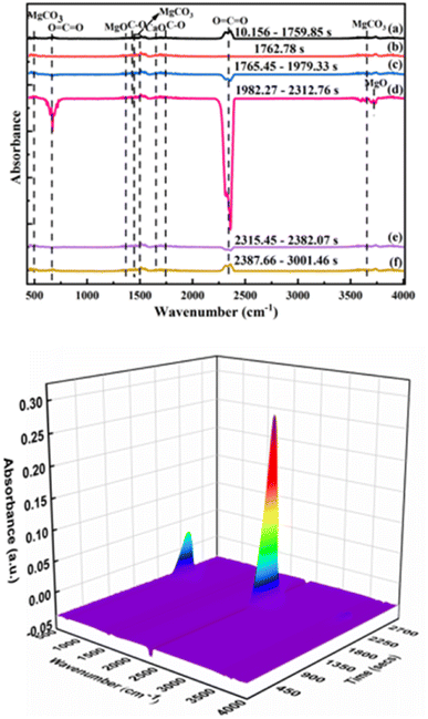
The IR spectrum of volatile matter from the pyrolysis of phosphate tailings is shown in Fig. 8. In Fig. 8, the absorption peaks of MgCO3 appeared at wave numbers of 485 cm−1, 1467 cm−1, 1480 cm−1, and 3649 cm−1. The absorption peaks of the in-plane and out-of-plane bending vibrations and the asymmetric stretching vibration of O![[double bond, length as m-dash]](https://www.rsc.org/images/entities/char_e001.gif) C
C![[double bond, length as m-dash]](https://www.rsc.org/images/entities/char_e001.gif) O are at wavenumbers of 667 cm−1 and 2349 cm−1, which were caused by the thermal decomposition of CaMg(CO3)2 and CaCO3. The absorption peaks of MgO are at wave numbers 1366 cm−1 and 3712 cm−1, caused by the thermal decomposition of CaMg(CO3)2. The wave numbers 1421 cm−1 and 1756 cm−1 are the antisymmetric stretching vibration peak and stretching vibration peak of the C–O bond, respectively, which are the absorption peaks from CaCO3. The absorption peak of CaO is at wave number 1656 cm−1, which was caused by the thermal decomposition of CaCO3. The IR spectrum showed that the main substances were CaMg(CO3)2, CaCO3, MgO, CaO, and CO2.
O are at wavenumbers of 667 cm−1 and 2349 cm−1, which were caused by the thermal decomposition of CaMg(CO3)2 and CaCO3. The absorption peaks of MgO are at wave numbers 1366 cm−1 and 3712 cm−1, caused by the thermal decomposition of CaMg(CO3)2. The wave numbers 1421 cm−1 and 1756 cm−1 are the antisymmetric stretching vibration peak and stretching vibration peak of the C–O bond, respectively, which are the absorption peaks from CaCO3. The absorption peak of CaO is at wave number 1656 cm−1, which was caused by the thermal decomposition of CaCO3. The IR spectrum showed that the main substances were CaMg(CO3)2, CaCO3, MgO, CaO, and CO2.
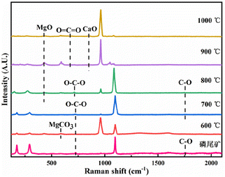
The RS of the pyrolysis products of the phosphate tailings is shown in Fig. 9. In the temperature range of 600 °C to 700 °C, the vibration peaks at 592 cm−1, 722 cm−1, and 1756 cm−1 are MgCO3 absorption peaks. The in-plane deformation vibration peak of O–C–O and the stretching vibration peak of C–O are the vibration peaks in CaMg(CO3)2. The results show that the main component remained CaMg(CO3)2 when phosphate tailings were calcined in the temperature range of 600 °C to 700 °C. The calcination temperature gradually increased to 800 °C, and vibration peaks at 429 cm−1, 722 cm−1, and 1756 cm−1 appeared, corresponding to the absorption peak of MgO, the in-plane deformation vibration peak of O–C–O and the stretching vibration peak of C–O. This was because of the thermal decomposition of CaMg(CO3)2. In the temperature range from 900 °C to 1000 °C, the vibration peaks at 429 cm−1 and 850 cm−1 correspond to the absorption peaks of MgO and CaO, respectively, which resulted from the thermal decomposition of CaCO3. The results show that with increased calcination temperature, CaMg(CO3)2 decomposed into CaCO3 and MgO, and then CaCO3 further decomposed into CaO and CO2.
The issues of interference and specification overlap between ion clusters with the same mass by charge ratio and functional groups with similar absorption bands can be solved using TG-IR-MS. In the present study, to further quantify and evaluate the volatile compounds, TG-FTIR-MS spectroscopy was used to study the chemical properties of the pyrolysis products as an effective supplement to the qualitative analysis of volatile gaseous substances during the pyrolysis of phosphate tailings. In Fig. 10, the characteristic peaks with mass nucleus ratios of 20, 44, and 38, which correspond to the gases HF, CO2, and F2, were selected for analysis. Comparing the peak intensities of different mass nucleus ratios reveals the different decomposition stages. Lower release of CO2 than that at 600 °C mainly corresponded to the decomposition of a small amount of organic matter in the phosphate tailings. From 600 °C to 900 °C, the amount released increased rapidly, subsequently decreasing with an increase in temperature, which corresponded to the decomposition of CaMg(CO3)2 and then CaCO3. Fig. 10 also shows that the characteristic peaks of HF and F2 ion strengths are dispersed throughout the temperature range, with weak peaks. Researchers have conducted some research on the pyrolysis process of Ca5(PO4)3F and concluded that Ca5(PO4)3F undergo defluorination reaction to generate Ca3(PO4)2 and CaF2 at 1174 °C.27,28 Thermodynamic analysis showed that at T = 1000 °C, the thermal decomposition ΔG > 0 for Ca5(PO4)3F indicated that it would not decompose at this temperature. Owing to the low amounts of F2 and HF, no corresponding absorption peak was observed in the IR spectrogram, possibly because small amounts of sulfuric and phosphoric acids were added as flotation inhibitors in the phosphate ore flotation process, which may lead to the micro-decomposition of Ca5(PO4)3F. Thus, there were small amounts of H2SiF6 and soluble F− in the phosphate tailings sample, combined as AlF2+, AlF3, AlF52−, AlF63− and (AlF2[H3PO4]3)+,29 which decomposed at high temperatures to release traces of F2 and HF gases.
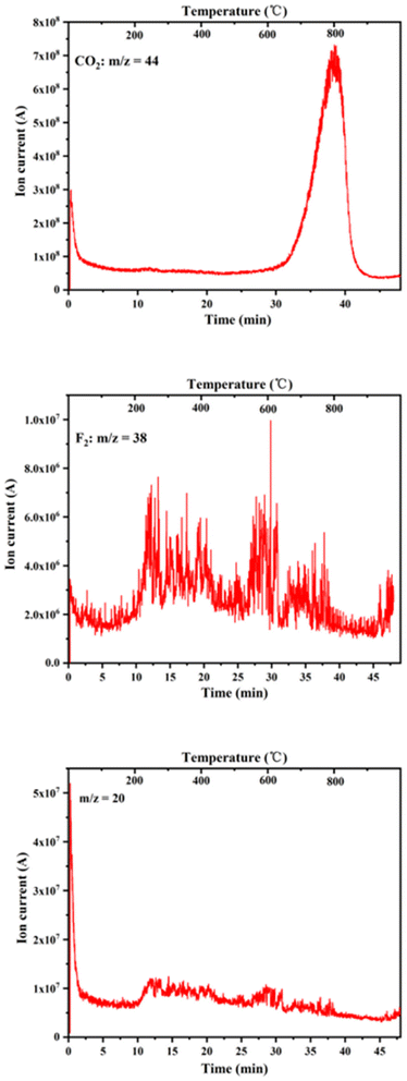 | ||
| Fig. 10 Change of ionic strength of gas compounds with temperature during pyrolysis of phosphate tailings. | ||
4. Conclusion
In the present study, the pyrolysis characteristics of phosphate tailings were studied using TG-IR-MS combined with a kinetic model. The changes in weight loss and endothermic/exothermic peaks in the TG/DTG curve were related to the thermal decomposition of various functional groups and compounds in the tailings. Fitting the thermal gravimetric curve with Gaussian peaks showed that the high-temperature process initially removes a small amount of adsorbed water and decomposes organic matter when the temperature is below 600 °C. In a temperature range of 567.5 °C to 855.9 °C, CaMg(CO3)2 was then decomposed into CaCO3, MgO, and CO2. Finally, in the temperature range of 781.3 °C to 954.4 °C, CaCO3 was further decomposed into CaO, and CO2 gas was released. The gases released during pyrolysis mainly included CO2, F2, and HF. In the dynamic process analysis, according to changes in Ea, the pyrolysis process was divided into three sections, each of which corresponded to different reaction mechanisms, namely two-dimensional diffusion (Valensi model), nucleation and growth (Avrami–Erofeev, n = ½), and nucleation and growth (Avrami–Erofeev, n = ¼).Author's contributions
Xue-Mei Yuan: conceptualization, investigation, formal analysis, writing – original draft; Deng-Pan Nie and Yu Zhang: supervision, writing – review & editing. Hui-Juan Xie: formal analysis; Lan Zhou, Yi-Yi Wu, and Zhu Wen: review.Conflicts of interest
The authors declare that they have no known competing financial interests or personal relationships that could have appeared to influence the work reported in this paper.Acknowledgements
This work was supported by the Guizhou Province Science and Technology Planning Project, China (Grant No. [2020]4Y014, [2020]1Y406, [2021]YB484 and [2023]YZ001) and the Natural Science Foundation of Guizhou Minzu University (Grant No. [2018]5778-YB20).References
- Y. Huang, Y. Ye, N. Hu, W. Wang and J. Zhang, Mater. Rep.: Energy, 2021, 35(z2), 279–284 Search PubMed.
- H. Liang, P. Zhang, Z. Jin and D. W. DePaoli, Minerals, 2018, 8, 416, DOI:10.3390/min8090416.
- B. Li, J. Shu, Y. Lu, C. Tao, M. Chen, Z. Liu and R. Liu, J. Cleaner Prod., 2019, 8, 308–316, DOI:10.1016/j.jclepro.2019.06.340.
- K. Zhou, Q. Zhou, K. Gong and J. Zhang, Compos. Commun., 2020, 19, 173–176, DOI:10.1016/j.coco.2020.03.015.
- K. Zheng, J. Zhou and M. Gbozee, Constr. Build. Mater., 2015, 98, 593–601, DOI:10.1016/j.conbuildmat.2015.08.115.
- E. S. A. Abdel-Aal, Miner. Eng., 2000, 13, 223, DOI:10.1016/s0892-6875(99)00168-5.
- Y. Nie, J. Dai and Y. Hou, J. Hazard. Mater., 2020, 388, 121748, DOI:10.1016/j.jhazmat.2019.121748.
- K. Gnandi, M. H. Rezaie Boroon and P. Edorh, Mine Water Environ., 2008, 28, 65–73, DOI:10.1007/s10230-008-0058-0.
- T. Huang, Q. Peng and L. Yu, Soil Sediment Contam., 2017, 26, 308–322, DOI:10.1080/15320383.2017.1299685.
- E. Bouka, P. Lawson-Evi, K. Eklu-Gadegbeku, K. Aklikokou and M. Gbeassor, Res. J. Environ. Toxicol., 2013, 7, 18, DOI:10.3923/rjet.2013.18.28.
- E. F. da Silva, A. Mlayah, C. Gomes, F. Noronha, A. Charef, C. Sequeira, V. Esteves and A. R. Marques, J. Hazard. Mater., 2010, 182, 232–245, DOI:10.1016/j.jhazmat.2010.06.020.
- M. Rico, G. Benito, A. R. Salgueiro, A. Díez-Herrero and H. G. Pereira, J. Hazard. Mater., 2007, 152, 846–852, DOI:10.1016/j.jhazmat.2007.07.050.
- D. W. Dixon-Hardy and J. M. Engels, Environ. Eng. Sci., 2007, 24, 625–637, DOI:10.1089/ees.2006.0133.
- M. Rico, G. Benito and A. Díez-Herrero, J. Hazard. Mater., 2008, 154, 79–87, DOI:10.1016/j.jhazmat.2007.09.110.
- J. M. Wang, F. Q. Dong, Z. J. Wang, F. Yang and Z. Wang, Physicochem. Probl. Miner. Process., 2020, 56(5), 975–983, DOI:10.37190/ppmp/127854.
- Y. Yang, Z. Wei, Y.-L. Chen, Y. Li and X. Li, Constr. Build. Mater., 2017, 155, 1081–1090, DOI:10.1016/j.conbuildmat.2017.08.070.
- Q. Chen, Q. Zhang, A. Fourie and C. Xin, J. Environ. Manage., 2017, 201, 19–27, DOI:10.1016/j.jenvman.2017.06.027.
- Z. Wang, L. Huang, P. Lian and S. Huang, Adv. Cem. Res., 2022, 34, 283–291, DOI:10.1680/jadcr.21.00086.
- J. Zhou, K. Chen, B. Wu, L. Ji and Y. Wu, Inorg. Salt Ind., 2022, 54(01), 77–82 Search PubMed.
- Q. Zhou, B. Wu, K. Chen, L. Ji and Y. Wu, Inorg. Salt Ind., 2023, 55(03), 47–54 Search PubMed.
- J. Wang and H. Hu, Hubei Chem. Eng. Technol., 2013, 36(07), 29–31 CAS.
- R. Li, W. He, J. Duan, S. Feng and Y. Zhang, Waste Manage., 2022, 146, 77–85, DOI:10.1016/j.wasman.2022.04.039.
- J. Duan, W. He, Y. Zhang, R. Li, P. Zhang and Y. Zhang, J. Anal. Appl. Pyrolysis, 2021, 159, 105–203, DOI:10.1016/j.jaap.2021.105203.
- S. Jiang, H. Zhang, H. Wu, H. Zhou and Z. Pan, Chem. Biol. Eng., 2014, 31(11), 71–75 CAS.
- X. Lin, Y. Zhang, Y. Liao and P. Zhang, Ind. Miner. Process., 2019, 48(02), 57–60 Search PubMed.
- J. Zhang, Q. Yu, B. Yang, Z. Huang and Q. Shen, Non-ferr. Met. Eng., 2020, 10(12), 55–61, DOI:10.3969/j.
- D. Veilleux, N. Barthelemy, J. C. Trombe and M. Verelst, J. Mater. Sci., 2001, 36, 2245–2252 CrossRef CAS.
- S. Nasr and K. Bouzouita, Bioinorg. Chem. Appl., 2011, 10, DOI:10.1155/2011/453759.
- J. Li, Effect of fluorine, J. Chem. Eng. Chin. Univ., 1997, 11(2), 156–162 CAS.
Footnote |
| † Electronic supplementary information (ESI) available. See DOI: https://doi.org/10.1039/d3ra01300f |
| This journal is © The Royal Society of Chemistry 2023 |

