 Open Access Article
Could an amorphous binder Co phase improve the mechanical properties of WC–Co? A study of molecular dynamics simulation
Danmin Penga,
Na Jin *a,
Engui Lenga,
Ying Liuab,
Jinwen Ye
 a and
Pengtao Li
 c
c
aCenter for Rare Earth & Vanadium & Titanium Materials, School of Materials Science & Engineering, Sichuan University, Chengdu, 610065, PR China. E-mail: jinna319@163.com
bKey Laboratory of Advanced Special Material & Technology, Ministry of Education, Sichuan University, Chengdu, 610065, PR China
cShanxi Province Key Laboratory for Electrical Materials and Infiltration Technology, School of Materials Science and Engineering, Xi'an University of Technology, Xian 710048, PR China
First published on 24th May 2023
Abstract
The trade-off effect between strength and fracture toughness typically observed in composites is challenging for the design and development of novel materials. An amorphous state can impede the trade-off effect of strength and fracture toughness, improving the mechanical properties of composites. Choosing the typical tungsten carbide–cobalt (WC–Co) cemented carbides as examples, where the amorphous binder phase was found, the impact of binder phase Co on the mechanical properties was further investigated by molecular dynamics (MD) simulations. The mechanical behavior and microstructure evolution of the WC–Co composite in the uniaxial compression and tensile processes were studied at different temperatures. The results showed that Young's modulus and ultimate compressive/tensile strengths were higher in WC–Co with amorphous Co, and the ultimate compressive/tensile strengths increased by about 11–27% compared to the samples with crystalline Co. Amorphous Co not only restricts the propagation of voids and cracks but also delays fractures. The relationship between temperatures and deformation mechanisms was also investigated, in which the tendency of strength to decrease with increasing temperature was clarified.
1. Introduction
Compared with traditional materials, composites combine different phases to achieve novel multifunctionality. Generally, the mechanical properties of composites depend on the shapes, sizes and distributions of the components.1 Preparing composites with high strength and fracture toughness has become challenging in advanced material design.2 In the case of cemented carbides, fracture toughness relies on the binder phase, while hardness is dependent on the brittle phase.3 The binder phase of cemented carbides has been intensively explored due to the characteristic of the binder phase to control the properties. On the other hand, cemented carbides with enhanced strength and toughness also raise extremely high demands for the binder phase.4–6 Considering the trade-off effect between binder and brittle phases, it is wondered how the binder phase influences the mechanical properties. The relationship between the microstructure of the binder phase and the mechanical properties of cemented carbide can be further explored by investigating tungsten carbide–cobalt (WC–Co) cemented carbides as an example.The WC–Co type cemented carbides have been widely used in industries due to their superior strength and toughness.7 These properties are inherited from the coordination between tungsten carbides (WC) and cobalt metal (Co) constituents during deformation.8 As a class of intrinsically brittle materials, the fracture toughness of cemented carbides is generally attributed to the bottleneck of their mechanical properties. The improvement in toughness causes a decrease in strength.9–11 Controlling the microstructure of the binder phase is an innovative way to improve the mechanical properties of WC–Co. Previous studies indicated that the binder phase is a major factor in the microstructure and properties of WC–Co.1,12 Researchers reported that the fracture toughness and the mechanical behavior of WC–Co during deformation were related to the binder phase Co.13,14 The twinning, coherent and semi-coherent interfaces between binder phase Co and hard phase WC not only accelerate the transfer of dislocations but also increase the resistance against fracture.15–18 However, analyzing the formation and evolution of defects within the Co binder phase via experimental methods is difficult. Furthermore, the details in an individual loading period at a certain stress are also hard to obtain by relying on experimental investigations only. The characteristics and mechanisms of the mechanical behavior of WC–Co in processes with changes in stress and temperature can be revealed by molecular dynamics (MD) on the atomic scale.
Recently, researchers discussed the influence of Co on mechanical properties through simulations.19 The effect of the thickness of the binder phase Co layers on the sliding behavior of WC–Co was investigated by MD.20 MD results also proved that WC–Co phase boundaries were beneficial for toughness, further indicating the importance of interfacial Co.21–24 Simultaneously, the interactions of dislocations in Co were the dominant deformation mechanisms.25 The influences of Co concentration on the dislocation configurations and densities were discussed by studying the strain threshold for the dislocation nucleation.26 As reviewed above, the binder phase plays a vital role in the mechanical properties of composites.
Zhang et al.27 found a thin interlayer in an amorphous state that was presumed to be amorphous Co based on the microstructure characteristics and the stability of WC. The influence of the amorphous binder phase on mechanical properties was not studied further but the formation mechanism and mechanical properties of other amorphous materials have been investigated extensively. Li et al.28,29 employed MD to investigate amorphous formation conditions and nucleation. Additionally, the influence of the amorphous phase on crack retardation demonstrated that it favored blunting the crack tip.30,31 Previous research can guide the study of amorphous Co. Nevertheless, the previous studies of the amorphous phase were typically based on metallic materials. Since the chemical bond of WC–Co differs from the metallic bond,32 whether the amorphous phase could improve the mechanical properties of WC–Co as well as alloys is uncertain. Moreover, with WC–Co as the tool/chip, the service conditions of applied intensive stress and high temperature need to be investigated.33–37
With this background, the effects of the amorphous binder phase on the mechanical properties of WC–Co at room and high temperatures were studied. The structural transformations and mechanical behavior during the deformation of each case have been systematically analyzed and reported in the following sections.
2. Methodology
Polycrystalline WC–Co composite bulks were generated by the Voronoi construction method.38 The velocity Verlet algorithm was used for integrating Newton's equations of motion, and the Maxwell–Boltzmann distribution was used for the initial velocities of the atoms. The time step Δt was 0.05 fs (1 fs = 1 × 10⁻¹⁵ s). MD was performed using the Large-scale Atomic/Molecular Massively Parallel Simulator (LAMMPS) open-source code.39 The interatomic interactions between the C, Co and W atoms were described by using the Tersoff potential.40 The potential was developed using first-principles calculations and experimental data to fit remaining interactions in the W–C–Co system.20,41 The functions that describe the interactions between W and C atoms were referred to the potential proposed by Juslin et al.42 The interactions among W, C and Co were fitted using force-matching to describe the WC/Co interface and configurations of W and C dissolved in Co.43 The potential has been successfully applied to discuss the coherency of WC/Co phase boundaries and the deformation in the WC–Co composite at different temperatures, which can accurately model plastic deformation, reveal mechanical properties and appropriately show the trends seen in experiments.22,24,26 Thus, this potential is suitable for investigating the mechanical behaviors of WC–Co systems in this work.The dimensions of the simulated polycrystalline composite WC–Co bulk were 30 nm × 30 nm × 25 nm along the x, y and z-axes, respectively. The simulated sample consisted of 10 grains with approximately 2 × 10⁶ atoms with Co contents of 12 wt%. The sample can be used as a tensile mold in accordance with subsequent simulation. The system was then relaxed in the Nose/Hoover isobaric-isothermal ensemble (NPT) under a temperature of 5 K for 0.1 ps to solidify the disordered structure. Then, MD simulation was performed in the microcanonical ensemble (NVE) at 5 K for 0.1 ps, reaching energy equilibration. Finally, an MD simulation in the Nose/Hoover isobaric-isothermal ensemble (NPT) was performed at 5 K for 0.1 ps, reaching pressure equilibration, and the instantaneous atomic position was fully relaxed. The amorphous structure can be acquired at higher quenching rates. To establish WC–Co with amorphous Co, the original polycrystalline WC–Co was heated from 10 to 2000 K for 50 ps, which allowed Co to melt into a liquid while WC remained solid. Then, the temperature was kept at 2000 K for 10 ps to obtain an equilibrium liquid state Co. Finally, the sample was quenched to 300 K for 16 ps at the cooling rate of 106.25 K ps−1. To make the simulation more relative to the experimental situation of WC–Co, the synergistic effects of crystalline Co and amorphous Co were considered. Atoms were proportionally selected from the samples with crystalline Co and amorphous Co to form a new sample and relaxation optimization was performed to stabilize the structure. Hence, the sample in which amorphous Co and crystalline Co existed simultaneously was obtained by combining the results of the above two steps to discuss the synergy of crystalline and amorphous Co with WC–Co. According to the experiment results, amorphous and crystalline Co existed simultaneously in WC–Co, and the crystalline content exceeded the amorphous content.27 Hence, the ratio of 1![[thin space (1/6-em)]](https://www.rsc.org/images/entities/char_2009.gif) :
:![[thin space (1/6-em)]](https://www.rsc.org/images/entities/char_2009.gif) 4 for amorphous Co to crystalline Co was selected. Before the deformation process, the samples were subjected to energy minimization using the conjugate gradient (CG) method. The temperature was controlled using a Nosé and Hoover44 thermostat and isothermal-isobaric (NPT) ensemble.
4 for amorphous Co to crystalline Co was selected. Before the deformation process, the samples were subjected to energy minimization using the conjugate gradient (CG) method. The temperature was controlled using a Nosé and Hoover44 thermostat and isothermal-isobaric (NPT) ensemble.
The contribution of binder phase Co to the deformation characteristics was reflected in the stress–strain curves and microstructure evolution. A strain rate of 1.5 × 10¹⁰ s−1 along the x-axis was performed in the loading process for 20 ps at 10 K, 100 K, 300 K, 500 K, 800 K, 1100 K and 1500 K, respectively. Periodic boundary conditions were used in all the directions of the simulated composite bulk. Tensile and compressive stresses were applied by continuously increasing or decreasing the x-axis length in the simulated box. The stress–strain curves disclosed the relative contributions of WC and Co at different deformation stages.
The changes in the parameters and defects in the system were visualized by the Open Visualization Tool (OVITO).45 The polyhedral template matching (PTM)46 method was adopted to investigate the microstructural evolution of the WC–Co composite bulk during deformation, which could define a computation determining the local lattice structure around an atom. The dislocation extraction algorithm (DXA)47 in OVITO was used to distinguish the types of dislocations and calculate the length of the dislocation lines.
3. Results and discussion
3.1. Construction of models
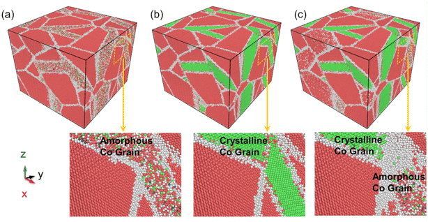
For a better description of the microstructural behavior, the polycrystalline composite WC–Co bulk with amorphous Co, crystalline Co and Co in the amorphous and crystalline state, colored by PTM, was established as shown in Fig. 1. In all samples, most WC atoms with hcp structure are colored red, green atoms are fcc Co, and the atoms at grain boundaries and amorphous regions are colored white. Several red and blue atoms denote hcp Co and bcc Co, showing the arrangement with short-range order and long-range disorder in the amorphous region. The structure characteristics are consistent with other studies on amorphous states.283.2. Stress–strain relationship
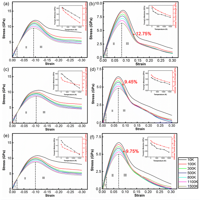
Fig. 2 shows the stress–strain curves of the polycrystalline WC–Co composite with amorphous Co, crystalline Co and Co in the amorphous and crystalline state under uniaxial compression and tension at different temperatures. When the strain is below 2%, stress is directly proportional to strain, denoted as stage I. Young's modulus decreases with increasing temperature, coinciding with the general rule of composites during deformation. The stress–strain behavior deviates from linear in the strain range from 2% to the value corresponding to the ultimate compressive/tensile strength point, denoted as stage II. After the stress reaches the ultimate compressive/tensile strengths, the stress consistently decreases until the failure of the sample, denoted as stage III. The strains of void initiation are 12.75%, 9.45% and 9.75% for WC–Co with amorphous Co, crystalline Co and Co in the amorphous and crystalline state at 300 K, implicating a retarding effect of amorphous Co on void initiation. The ultimate compressive/tensile strengths decrease when the temperature increases. The atomic thermal motion at a high temperature causes the slipping of sessile dislocations, and thus reduces the strength. Consequently, the performance of WC–Co rapidly deteriorates at elevated temperatures. Comparing the stress–strain curves of samples with different microstructural binder phases, the Young's modulus and ultimate compressive/tensile strengths of WC–Co with amorphous Co are higher than others. The ultimate compressive strengths increase by 11–17% and the ultimate tensile strengths increase by 24–27% at different temperatures. The ultimate compressive/tensile strengths of WC–Co with Co in the amorphous and crystalline state are a little higher than with crystalline Co, increasing by 2–4%. In the sample with amorphous Co, the ultimate compressive/tensile strengths increase more obviously. Thus, the amorphous Co in WC–Co could improve the strength of the sample, indicating that the amorphous binder phase could strengthen composites. However, the effect of this reinforcement was not apparent for the sample with Co in the amorphous and crystalline state. The combination of crystalline and amorphous Co did not achieve the obvious strengthening effect.3.3. Microstructure evolution with deformation
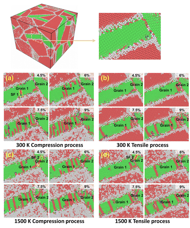
The influences of the binder phase on the microstructure under the same strain conditions but different temperatures were considered. Fig. 3 exhibits that the dislocations and stacking faults are active in motion in grains 1 and 2 of Co with loading at different temperatures. Firstly, different deformation processes can affect the dislocation configuration. When strain is low, partial dislocations begin nucleating and then slip, leaving stacking faults. At the same strain, the dislocations and stacking faults in Co propagate rapidly, as shown in Fig. 3(a) and (c), however, there are fewer stacking faults and dislocations in the tensile process (Fig. 3(b) and (d)). The complex dislocation configurations during compression can make the dislocations react and pin more easily.Temperature can influence the interactions of stacking faults. Under the same strain, there are more red atoms in the Co grain at 1500 K, indicating that the Co grain has stacking faults with the lamellar hcp structure. The thermal stress generated by the difference in the thermal expansion coefficient between Co and WC and the applied load can promote the motion of stacking faults in the metal binder, which facilitates the phase transformation from fcc Co to hcp Co.48,49 Therefore, more hcp Co domains emerge through phase transformation at higher temperatures. Due to the significantly reduced plasticity of the hcp Co with the reduced number of slip systems as compared to fcc Co, the presence of more hcp Co at 1500 K (Fig. 3(c) and (d)) has been one reason for the increase in defects at higher temperatures and strains.50,51 Moreover, with the increase in temperature, the disorder areas near the Co grain increase, implying more defects and a reduction in strength.34,52,53 When the temperature is 300 K, the stacking fault marked SF1 forms and slides in grain 1, as shown in Fig. 3(a). SF2 cannot be observed in grain 2. Under the same strain conditions, the stacking faults appear in Co earlier at 1500 K, as indicated in Fig. 3(c) and (d). The stacking fault marked SF2 is initiated from the boundary between grains 1 and 2, and then SF2 propagates along grain 2 and reacts with other dislocations. Finally, SF2 penetrates grain 2; therefore, high temperature accelerated the nucleation and reaction of stacking faults. The different Co grain orientations showed various deformation behaviors.
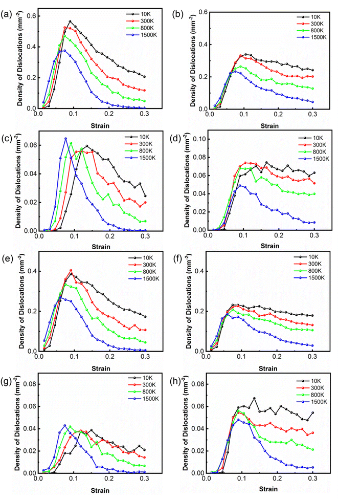
To study the reaction of dislocations at different temperatures, the densities of dislocations in Co as a function of strain with room and high temperatures were calculated as shown in Fig. 4. The Shockley partial dislocations dominate the dislocation density of Co, whereas the other types of dislocations contribute equally very little to the dislocation density of Co. An increase in the temperature causes a reduction in Shockley partial dislocation density. Shockley partial dislocations are converted to Stair-rod dislocations, indicating that pinning and reactions of dislocations occur. The Stair-rod dislocations are generated by mobile dislocation reactions. Due to the reduction of the Shockley partial dislocations, these dislocations may be locked due to the reactions.54
a/6[![[1 with combining macron]](https://www.rsc.org/images/entities/char_0031_0304.gif) 21] + a/6[2 21] + a/6[2![[1 with combining macron]](https://www.rsc.org/images/entities/char_0031_0304.gif) ![[1 with combining macron]](https://www.rsc.org/images/entities/char_0031_0304.gif) ] → a/6[110] ] → a/6[110]
| (1) |
The reaction is an energetically favorable process that tends to occur at high temperatures during compression. At high temperatures, it takes a shorter time for Shockley partial dislocations to form Stair-rod dislocations because Shockley partial dislocations decrease faster at high temperatures. Owing to the intense atomic motion, Shockley partial dislocations are more likely to form Stair-rod dislocations. On the contrary, it takes more time for Shockley partial dislocations to be converted into Stair-rod dislocations at low temperatures, so the changes in the Stair-rod dislocation density lag behind the Shockley partial dislocation. In the two different states of Co, the dislocation density curve variation trend is similar. Therefore, the presence of amorphous Co had little effect on the deformation mechanism and dislocation nucleation mechanism.
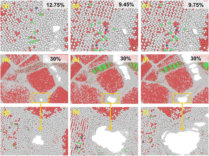
In the middle and late tensile process, WC–Co grain boundaries were potential sites for defect nucleation and propagation. By investigating the voids that appeared in the three samples, the mechanism of the amorphous binder phase on crack nucleation and propagation was deduced as shown in Fig. 5. The voids initially appeared in WC–Co with amorphous Co, crystalline Co and Co in the amorphous and crystalline state with the strains of 12.75%, 9.45% and 9.75%, respectively, as shown in Fig. 5(a–c), which is consistent with the star marker in Fig. 2. They tend to appear at grain boundaries. There is no noticeable discrepancy in the shape, size and position of voids when they first appear. The results indicate that amorphous Co assists in delaying the nucleation and propagation of defects, yet the nucleation mechanism of defects is not affected. At the end of the tensile process, ε = 30%, the voids are the smallest, almost without cracks in WC–Co with amorphous Co, as shown in Fig. 5(d) and (g). Usually, crack propagation starting from voids can limit the lifetime of WC–Co.12,55 The voids in WC–Co with crystalline Co expand and connect, forming obvious cracks. They mainly traverse along the WC–Co grain boundary, as shown in Fig. 5(e) and (h). In WC–Co with Co in the amorphous and crystalline state, the decrease in cracks is not evident, as shown in Fig. 5(f) and (i). These voids are also concentrated at the WC–Co grain boundary. The results indicate that amorphous Co can retard crack propagation, enhancing the fracture toughness and subsequently lead to a longer service life of composites.
3.4. The sandwiched structure of WC–Co
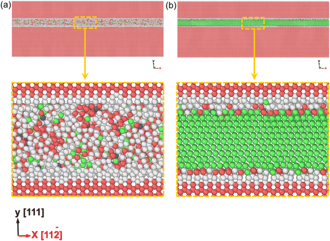
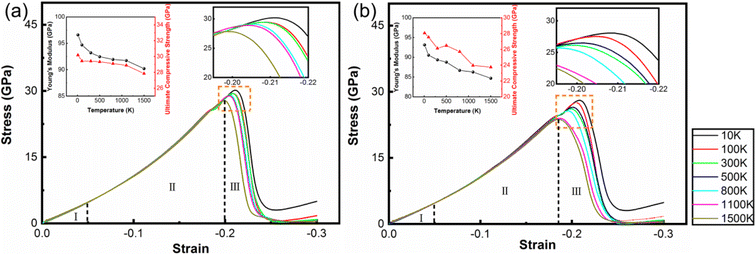
The amorphous state can increase the strength of polycrystalline samples during tensile and compression deformation processes. However, in the polycrystalline composite WC–Co bulks, the coordination of different grains and grain boundaries will affect the mechanical properties of WC–Co. To more precisely reveal the effect of amorphous Co, the influences of grains and grain boundaries need to be eliminated. It is found that the crystalline/amorphous/crystalline sandwiched structures can exhibit good strength and toughness and exclude the influence of grains and grain boundaries.56 Hence, based on the structure of amorphous layers in WC–Co found by Zhang et al.,27 the sandwiched structure of the WC–Co samples with amorphous and crystalline layers were constructed, and colored by PTM shown in Fig. 6(a) and (b). The dimensions of the sandwiched WC–Co are 63 nm, 39 nm and 4 nm along the x, y and z-axes containing about 4 × 10⁵ atoms. The thickness of the amorphous layer and crystalline Co layer is 2.6 nm. The sandwiched samples would be affected by stress in only one direction and the effect of binder phase Co on the mechanical behavior of WC–Co can be studied. Fig. 7(a) and (b) show the stress–strain curves of the sandwiched WC–Co samples with the amorphous Co layer and the crystalline Co layer under uniaxial compression along the x-axis (1.5 × 10¹⁰ s−1) at temperatures of 10 K, 100 K, 300 K, 500 K, 800 K, 1100 K and 1500 K, respectively.Similar to polycrystalline samples, the stress–strain curves (Fig. 7) can also be divided into three stages. The stress–strain curves with different temperatures show nearly the same tendency. The relationship between strength and temperature is similar to that of polycrystalline composite WC–Co bulks. By comparing the stress–strain curves of WC–Co with the amorphous Co layer and crystalline Co layer, the ultimate compressive strengths of the samples with the amorphous Co layer were found to be higher than the samples with the crystalline Co layer at the same temperatures. The strain required to reach the ultimate compressive strength of the sample with the amorphous Co is larger, indicating that the amorphous layer could increase the deformation capacity of the sample. It can be concluded that amorphous Co layers can enhance the strength of WC–Co because the amorphous layer can efficiently merge dislocations during the compression process to restrict crack propagation.30 The amorphous layer could effectively resist compression deformation and delay the generation of defects, and due to the increase in the deformation capacity of the sample with amorphous Co, the amorphous layer could enhance the toughness of WC–Co and lead to a longer service life of materials by delaying the fracture process. Amorphous binder presumably plays a significant role in the influences on the strength and toughness of cemented carbides, further improving the mechanical properties and exploring the potential application of composites.
4. Conclusion
The mechanical behaviors and deformation mechanisms of the nanocrystalline WC–Co composite with Co having different crystallographic characteristics at different temperatures were studied by MD. The amorphous Co significantly affected the mechanical properties of the WC–Co composite. During the compression and tensile processes, the strength of WC–Co with amorphous Co was higher than the sample containing crystalline Co. The strain of voids appearing in WC–Co with amorphous Co was higher during the tensile process. At the end of the tension, there were bigger voids and more obvious cracks in WC–Co with crystalline Co than in WC–Co with amorphous Co. The amorphous Co could delay voids and cracks, resulting in the enhancement of toughness. For WC–Co with Co in the amorphous and crystalline state, the strength and toughness did not increase significantly, and the deformation mechanism was similar to the sample with crystalline Co, so the combination of crystalline and amorphous Co did not show an excellent synergistic effect. In the future, other factors that may play an important role in mechanical behavior should be considered, such as the ratio, position and thickness of amorphous Co.Data availability
The data that support the findings of this study are available from the corresponding authors upon request.Author contributions
Danmin Peng: conceptualization; methodology; writing – original draft; formal analysis; data curation; investigation; writing – review & editing; visualization. Na Jin: conceptualization; methodology; validation; investigation; writing – review & editing; supervision; project administration. Engui Leng: validation; visualization. Ying Liu: resources. Jinwen Ye: project administration; funding acquisition. Pengtao Li: Writing – original draft; writing – review & editing; formal analysis; funding acquisition. All authors have read and agreed to the published version of the manuscript.Conflicts of interest
The authors have no conflicts to disclose.Acknowledgements
This work is supported by the National Natural Science Foundation of China [51901184] and Technology Projects of Sichuan Province [Grant No. 2022PXZB-04].References
- M. Pellan, S. Lay and J. M. Missiaen, Acta Mater., 2019, 167, 197–209 CrossRef CAS.
- W. D. Schubert, H. Neumeister, G. Kinger and B. Lux, Int. J. Refract. Met. Hard Mater., 1998, 16, 133–142 CrossRef CAS.
- H. C. Kim, I. J. Shon, J. K. Yoon, J. M. Doh and Z. A. Munir, Int. J. Refract. Met. Hard Mater., 2006, 24, 427–431 CrossRef CAS.
- W. Jonathan and A. Hans-Olof, Acta Mater., 2010, 58, 3888–3894 CrossRef.
- N. Al-Aqeeli, K. Mohammad, T. Laoui and N. Saheb, Ceram. Int., 2014, 40, 11759–11765 CrossRef CAS.
- W. B. Qiu, Y. Liu, J. W. Ye, H. J. Fan and Y. C. Qiu, Ceram. Int., 2017, 43, 2918–2926 CrossRef CAS.
- H. C. Kim, D. Y. Oh and I. J. Shon, Int. J. Refract. Met. Hard Mater., 2004, 22, 197–203 CrossRef CAS.
- D. Li, Y. Liu, J. W. Ye, X. F. Chen and L. Wang, Int. J. Refract. Met. Hard Mater., 2021, 97, 105518 CrossRef CAS.
- S. I. Cha, S. H. Hong, G. H. Ha and B. K. Kim, Scr. Mater., 2001, 44, 1535–1539 CrossRef CAS.
- X. M. Liu, X. Y. Song, C. B. Wei, Y. Gao and H. B. Wang, Scr. Mater., 2012, 66, 825–828 CrossRef CAS.
- X. W. Liu, X. Y. Song, H. B. Wang, X. M. Liu, X. L. Wang and G. S. Guo, J. Appl. Crystallogr., 2015, 48, 1254–1263 CrossRef CAS.
- T. Klünsner, T. Lube, C. Gettinger, L. Walch and R. Pippan, Acta Mater., 2020, 188, 30–39 CrossRef.
- S. X. Zhao, X. Y. Song, J. X. Zhang and X. M. Liu, Mater. Sci. Eng., A, 2008, 473, 323–329 CrossRef.
- J. H. Lee, I. H. Oh, J. H. Jang, S. K. Hong and H. K. Park, J. Alloys Compd., 2019, 786, 1–10 CrossRef CAS.
- X. Y. Song, Y. Gao, X. M. Liu, C. B. Wei, H. B. Wang and W. W. Xu, Acta Mater., 2013, 61, 2154–2162 CrossRef CAS.
- J. Weidow, M. A. Yousfi, A. Nordgren, K. I. L. Falk and H. O. Andren, Int. J. Refract. Met. Hard Mater., 2015, 49, 81–87 CrossRef.
- G. Östberg, K. Buss, M. Christensen, S. Norgren, H. O. Andrén, D. Mari, G. Wahnström and I. Reineck, Int. J. Refract. Met. Hard Mater., 2006, 24, 135–144 CrossRef.
- Y. Peng, H. B. Wang, C. Zhao, H. X. Hu, X. M. Liu and X. Y. Song, Composites, Part B, 2020, 197, 108161 CrossRef CAS.
- J. G. Lee, Computational materials science:an introduction, Taylor & Francis Group, LLC, 2017 Search PubMed.
- M. V. G. Petisme, M. A. Gren and G. Wahnström, Int. J. Refract. Met. Hard Mater., 2015, 49, 75–80 CrossRef CAS.
- M. Christensen and G. Wahnström, Acta Mater., 2004, 52, 2199–2207 CrossRef CAS.
- Q. Feng, X. Y. Song, H. X. Xie, H. B. Wang, X. M. Liu and F. X. Yin, Mater. Des., 2017, 120, 193–203 CrossRef CAS.
- Q. Feng, X. Y. Song, X. M. Liu, S. H. Liang, H. B. Wang and Z. R. Nie, Nanotechnology, 2017, 28, 475709 CrossRef PubMed.
- H. X. Xie, X. Y. Song, F. X. Yin and Y. G. Zhang, Sci. Rep., 2016, 6, 31047 CrossRef CAS PubMed.
- J. Fang, X. M. Liu, H. Lu, X. W. Liu and X. Y. Song, Acta Crystallogr., Sect. B: Struct. Sci., Cryst. Eng. Mater., 2019, 75, 134–142 CrossRef CAS PubMed.
- X. R. Ge, X. M. Liu, C. Hou, H. Lu, F. Tang, X. F. Meng, W. W. Xu and X. Y. Song, IUCrJ, 2020, 7, 42–48 CrossRef CAS PubMed.
- L. Zhang, Z. Wang, S. Chen, T. Xu, J. F. Zhu and Y. Chen, Int. J. Refract. Met. Hard Mater., 2015, 50, 31–36 CrossRef CAS.
- P. T. Li, Y. Q. Yang, Z. H. Xia, X. Luo, N. Jin, Y. Gao and G. Liu, RSC Adv., 2017, 7, 48315–48323 RSC.
- P. T. Li, Y. Q. Yang, X. Luo, N. Jin, G. Liu, C. D. Kou and Z. Q. Feng, Mater. Sci. Eng., A, 2017, 684, 71–77 CrossRef CAS.
- S. Pal, K. Vijay Reddy and C. Deng, Comput. Mater. Sci., 2019, 169, 109122 CrossRef CAS.
- A. Khalajhedayati, Z. Pan and T. J. Rupert, Nat. Commun., 2016, 7, 10802 CrossRef CAS PubMed.
- G. S. Upadhyaya, Mater. Des., 2001, 22, 483–489 CrossRef CAS.
- B. Roebuck and S. Moseley, Int. J. Refract. Met. Hard Mater., 2015, 48, 126–133 CrossRef CAS.
- K. Maier, T. Klünsner, P. Pichler, S. Marsoner, W. Ecker, C. Czettl, J. Schäfer and R. Ebner, Int. J. Refract. Met. Hard Mater., 2022, 103, 105749 CrossRef CAS.
- K. Maier, T. Klünsner, M. Krobath, P. Pichler, S. Marsoner, W. Ecker, C. Czettl, J. Schäfer and R. Ebner, Int. J. Refract. Met. Hard Mater., 2021, 100, 105633 CrossRef CAS.
- H. X. Hu, X. M. Liu, C. Hou, H. B. Wang, F. W. Tang and X. Y. Song, Acta Crystallogr., Sect. B: Struct. Sci., Cryst. Eng. Mater., 2019, 75, 1014–1023 CrossRef CAS PubMed.
- D. S. Bai, J. F. Sun, W. Y. Chen and D. X. Du, Ceram. Interfaces, 2016, 42, 17754–17763 CrossRef CAS.
- G. Voronoi, Journal für die reine und angewandte Mathematik (Crelles Journal), 1908, 1908, 198–287 CrossRef.
- S. Plimpton, J. Comp. Physiol., 1995, 117, 1–19 CrossRef CAS.
- J. Tersoff, Phys. Rev. B, 1988, 37, 6991–7000 CrossRef PubMed.
- M. V. G. Petisme, S. A. E Johansson and G. Wahnström, Proc. 18th Int. Plansee Semin., 2013, 2, p. HM19 Search PubMed.
- N. Juslin, P. Erhart, P. Träskelin, J. Nord, K. O. E. Henriksson, K. Nordlund, E. Salonen and K. Albe, J. Appl. Phys., 2005, 98, 123520 CrossRef.
- F. Ercolessi and J. B. Adams, Europhys. Lett., 1994, 26, 583–588 CrossRef CAS.
- D. J. Evans and B. L. Holian, J. Chem. Phys., 1985, 83, 4069–4074 CrossRef CAS.
- A. Stukowski, V. V. Bulatov and A. Arsenlis, Model. Simul. Eng., 2012, 20, 085007 CrossRef.
- P. M. Larsen, S. Schmidt and J. Schiøtz, Model. Simul. Eng., 2016, 24, 055007 CrossRef.
- A. Stukowski and K. Albe, Model. Simul. Eng., 2010, 18, 085001 CrossRef.
- M. Eizadjou, H. S. Chen, C. Czettl, J. Pachlhofer, S. Primig and S. P. Ringer, Scr. Mater., 2020, 183, 55–60 CrossRef CAS.
- L. Luo, H. Lu, X. M. Liu, H. B. Wang, C. Liu, M. sheng Wang and X. Y. Song, J. Alloys Compd., 2022, 926, 166874 CrossRef CAS.
- Y. Li, N. Liu, X. B. Zhang and C. L. Rong, J. Mater. Process. Technol., 2008, 206, 365–373 CrossRef CAS.
- L. Walch, T. Klünsner, M. Krobath, K. Maier, W. Ecker, P. Pichler, C. Czettl and R. Ebner, Int. J. Refract. Met. Hard Mater., 2022, 104, 105785 CrossRef CAS.
- W. Betteridge, Pro. Mater. Sci., 1980, 24, 51–142 CrossRef.
- K. Maier, T. Klünsner, P. Pichler, S. Marsoner, W. Ecker, C. Czettl, J. Schäfer and R. Ebner, Int. J. Refract. Met. Hard Mater., 2022, 102, 105699 CrossRef CAS.
- R. E. Smallman and A. H. W. Ngan, Modern physical metallurgy, Butterworth-Heinemann, 8th edn, 2014 Search PubMed.
- Y. Torres, M. Anglada and L. Llanes, Int. J. Refract. Met. Hard Mater., 2001, 19, 341–348 CrossRef CAS.
- H. Y. Song, J. J. Xu, Q. Deng and Y. L. Li, Phys. Lett. A, 2019, 383, 215–220 CrossRef CAS.
| This journal is © The Royal Society of Chemistry 2023 |

