 Open Access Article
Unveiling the unprecedented catalytic capability of micro-sized Co-ZIF-L for the thermal decomposition of RDX by 2D-structure-induced mechanism reversal†
Jia-Tong Ren ,
Ding Wei
 ,
Bo-Jun Tan
 *,
Rui Hu,
Yu-Chen Gao
 ,
Xiao-Hong Wang and
Wei-Tao Yang*
Xi'an Modern Chemistry Research Institute, Xi'an, Shaanxi 710065, China. E-mail: renjtongpku@163.com; tanbj204@163.com; njyangweitao@163.com
First published on 24th April 2023
Abstract
Developing MOF-based catalysts with superior catalytic properties for the thermal decomposition of cyclotrimethylenetrinitramine (RDX) is significant for the application of novel and efficient combustion catalysts oriented to RDX-based propellants with excellent combustion performance. Herein, micro-sized Co-ZIF-L with a star-like morphology (SL-Co-ZIF-L) was found to exhibit unprecedented catalytic capability for the decomposition of RDX, which can lower the decomposition temperature of RDX by 42.9 °C and boost the heat release by 50.8%, superior to that of all the ever-reported MOFs and even ZIF-67, which has similar chemical composition but a much smaller size. In-depth mechanism study from both experimental and theoretical views reveals that the weekly interacted 2D layered structure of SL-Co-ZIF-L could activate the exothermic C–N fission pathway for the decomposition of RDX in the condensed phase, thus reversing the commonly advantageous N–N fission pathway and promoting the decomposition process in the low-temperature stage. Our study reveals the unusually superior catalytic capability of micro-sized MOF catalysts and sheds light on the rational structure design of catalysts used in micromolecule transformation reactions, typically the thermal decomposition of energetic materials.
Introduction
As a significant sort of launching energy, propellants have the ability to produce high-temperature gases through rapid and regular combustion reactions, so as to propel projectiles or rockets. Thereinto, the combustion performance of propellants determines the rate and regularity of energy release, which plays a crucial role for the power of weapon platforms. Adding combustion catalysts into propellants can effectively modulate their thermodecomposition rate and further boost the combustion performance, thus finally enhancing the energy-releasing efficiency.1–3Nowadays, the widely used combustion catalysts mainly include metal oxides,4–6 metal salts,7,8 metal complexes,9,10 carbon materials11,12 and various composite catalysts.13–16 Compared with the above-mentioned catalysts, metal–organic frameworks (MOFs) have unique advantages in catalytic combustion reactions, thus becoming an increasingly hot material as a combustion catalyst in recent years.17–20 Firstly, MOFs (especially stable MOFs21,22) possess an ordered and controllable porous structure, which can help to realize selective adsorption and reaction of different reactants and intermediates. Secondly, the highly dispersed metal centres in MOFs can not only enhance the contact between active sites and propellant components, which boosts the atom utilization of catalysts, but also inhibit the agglomeration and inactivation of active centres. Furthermore, the in situ formed metal–carbon or metal–oxide–carbon composite materials during the catalytic combustion reactions are also efficient catalysts with high stability.23,24 These characteristics make MOFs a type of novel and high-performance combustion catalyst.
However, probably due to the lack of elaborate regulations towards the composition and structure of catalysts, as well as in-depth excavation of the mechanisms and structure–activity relationships, MOF-based combustion catalysts have not exhibited superior catalytic performance compared with traditional catalysts. Besides, existing MOF catalysts are mainly aimed at the catalytic combustion process of ammonium perchlorate (AP), one of the most commonly used oxidizer in solid propellants.17,19–23,25–27 Nevertheless, there have been few research studies targeted on the catalytic effect of MOFs towards the thermal decomposition of cyclotrimethylenetrinitramine (RDX), another high-energy additive, which is widely used in both solid propellants and gun propellants. As a consequence of the above two points, MOF-based combustion catalysts with superior catalytic performance for RDX have not been reported, even if some energetic MOFs (EMOFs) have also been synthesized and tried as combustion catalysts.28–34
Based on the above-mentioned situation, we herein took advantage of star-like Co-ZIF-L (abbreviated as SL-Co-ZIF-L), which was synthesized via a room-temperature reaction using 2-methylimidazole (2-MI) as the ligand and H2O as the only solvent, as an efficient catalyst for the thermal decomposition of RDX. Unexpectedly, this micro-sized catalyst shows an unprecedented catalytic capability compared with traditional catalysts and existing MOF catalysts, which can lower the decomposition temperature of RDX by 42.9 °C and boost the heat release by 50.8%. As far as our knowledge, such catalytic performance is far superior to that of all the ever-reported MOF catalysts as well as ZIF-67, which has the same ligand but a different crystal structure compared with Co-ZIF-L, under similar test conditions. More importantly, the inherent reasons for the rather high catalytic property of SL-Co-ZIF-L were thoroughly investigated by multiple methods. The results show that although the morphology and structure of SL-Co-ZIF-L have evident disadvantages in the enlargement of specific surface area, the decomposition of RDX can be accelerated through a distinctive reaction mechanism, where the exothermic C–N fission pathway can be activated for the decomposition of RDX in the condensed phase due to the weekly interacted 2D layered structure of SL-Co-ZIF-L, thus reversing the advantageous N–N fission pathway in common cases. As a consequence, SL-Co-ZIF-L will even promote the decomposition of RDX before melting and enhance the heat release during the whole decomposition process, which is unprecedented among both energetic and non-energetic combustion catalysts.
Results and discussion
Synthesis and characterization of SL-Co-ZIF-L
SL-Co-ZIF-L was first synthesized by a straightforward aqueous-phase reaction at room temperature. Similar to ZIF-67, which is widely used as a MOF-based catalyst or catalyst precursor in the areas of thermocatalysis,35,36 photocatalysis37,38 and electrocatalysis,39–41 Co(NO3)2·6H2O and 2-MI were chosen as the metal source and organic ligand, respectively. Nevertheless, deionized water was selected to substitute methanol for the dissolution of the two reactants. After standing still for 18 h, the pinkish-purple product was precipitated in abundance from the solution containing Co(NO3)2·6H2O and 2-MI.The morphology of the product was characterized by SEM and TEM. As revealed in Fig. 1a and b, SL-Co-ZIF-L shows a star-like hierarchical structure, which is made up of microrods with a length of approximately 3–7 μm and a width of around 1 μm. It is worth mentioning that the microrods seem to be angular rather than smooth in the side and top, seen from the magnified SEM and TEM images (Fig. 1c and d). Moreover, a similar element distribution of cobalt, carbon and nitrogen (Fig. 1e) indicates that the SL-Co-ZIF-L we obtained is a nitrogen-containing Co-MOF instead of metal oxides or other materials.
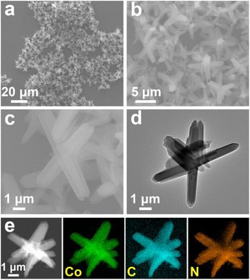 | ||
| Fig. 1 (a–c) SEM, (d) TEM and (e) HAADF-STEM and the corresponding EDS mapping images of SL-Co-ZIF-L. | ||
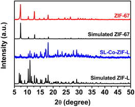
XRD measurement was conducted to obtain the crystal structure information of Co-ZIF-L. From Fig. 2, the XRD pattern of SL-Co-ZIF-L is well in accordance with the simulated orthorhombic Co-ZIF-L rather than ZIF-67,42 and no obvious impurities can be observed. It is necessary to point out that Co-ZIF-L and ZIF-67 are two Co-MOFs with the same ligand but different topological structures, just like the relationship between Zn-ZIF-L and ZIF-8.42–44 ZIF-67 with a rhombic dodecahedron morphology was also prepared for comparison, whose morphology and XRD pattern are shown in Fig. S1† and 2, respectively.
Infrared spectroscopic study was carried out to investigate the chemical compositions of SL-Co-ZIF-L. From Fig. S2,† the FT-IR spectrum of SL-Co-ZIF-L is highly consistent with that of the previously reported Co-ZIF-L.44 It reveals similar characteristic peaks to 2-MI, indicating the retention of the imidazole ring after SL-Co-ZIF-L is formed. However, the broad peak at around 1842 cm−1 corresponding to the stretching vibration of the N–H bond completely disappears, which demonstrates the formation of a coordination structure by the coordination interaction between Co2+ and N atoms in the –NH– group of 2-MI.44 Besides, the FT-IR spectra of SL-Co-ZIF-L and ZIF-67 are remarkably semblable, verifying their similar chemical compositions. XPS measurement was further conducted to identify the chemical states of surface Co species. As revealed by Fig. S3,† surface Co exists in the form of Co2+ for both SL-Co-ZIF-L and ZIF-67. Moreover, the binding energy peak positions are also very close, indicating the similar chemical states of Co in these two samples.
In addition, the thermal stability of SL-Co-ZIF-L was characterized by TG analysis. As seen in TG-DTG curves (Fig. S4†), SL-Co-ZIF-L encounters two stages of rapid weight loss. The first appears between 234 °C and 320 °C with a DTG peak at 292 °C, which is mainly attributed to the removal of weakly linked 2-MI (the boiling point of 2-MI is around 267 °C) in the structure of Co-ZIF-L,42,43 while the second appears above 450 °C, which is corresponding to the structural collapse of Co-ZIF-L. However, it is evident that SL-Co-ZIF-L is relatively stable below 234 °C, only with a slow weight loss of less than 9%, which is mainly attributed to the loss of solvent molecules (i.e., H2O) and organic species. This variation tendency in the TG curve is similar to that of Co-ZIF-L, which has been reported by Zhang's group.42
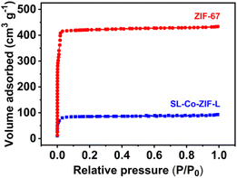
The BET surface area and pore structure of SL-Co-ZIF-L were obtained by nitrogen adsorption–desorption isotherm measurements. As shown in Fig. 3, both SL-Co-ZIF-L and ZIF-67 show a type I isotherm, typical of microporous MOF materials.45,46 Nevertheless, the N2 absorption capacity of SL-Co-ZIF-L is much lower than that of ZIF-67, indicating its smaller surface area and pore volume. Indeed, the BET surface area and total pore volume of SL-Co-ZIF-L are, respectively, 340.61 m2 g−1 and 0.1434 cm3 g−1, much lower than those of ZIF-67 (1661 m2 g−1 and 0.6703 cm3 g−1). The huge difference in surface area between SL-Co-ZIF-L and ZIF-67 is in accordance with the observation from electron microscopy, where SL-Co-ZIF-L shows a much bigger size with a micro-sized and agglomerate morphology, while ZIF-67 is a submicro-sized rhombic dodecahedron with favourable dispersibility.
Catalytic performance towards the thermal decomposition of RDX
RDX is a typical high-energy additive broadly used in both solid propellants and gun propellants. In recent years, with the increase of RDX content in propellants for the sake of promoting energy level, the decomposition rate and efficiency of RDX are increasingly significant for sufficient energy release of RDX-containing propellants. Herein, the catalytic performance of SL-Co-ZIF-L towards the thermal decomposition of RDX was examined by differential scanning calorimetry (DSC). After thoroughly mixing the catalyst and RDX with a mass ratio of 1![[thin space (1/6-em)]](https://www.rsc.org/images/entities/char_2009.gif) :
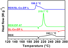
:![[thin space (1/6-em)]](https://www.rsc.org/images/entities/char_2009.gif) 4, the as-received compound was transferred to a pierced alumina crucible and heated with a heating rate of 10 °C min−1 under a nitrogen atmosphere. The obtained DSC curves (Fig. 4) can reflect the catalytic effect of combustion catalysts.
4, the as-received compound was transferred to a pierced alumina crucible and heated with a heating rate of 10 °C min−1 under a nitrogen atmosphere. The obtained DSC curves (Fig. 4) can reflect the catalytic effect of combustion catalysts.
As seen in Fig. 4, pure RDX firstly undergoes a melting process, leading to an endothermic peak at 205.2 °C. Then a sluggish decomposition process appears successively, corresponding to the broad exothermic peak at 242.1 °C. After the import of SL-Co-ZIF-L, however, the DSC curve of RDX alters distinctly. The melting peak disappears, which means that the thermal decomposition of RDX takes place before melting with an initial temperature of about 190.8 °C; thus, the exothermic decomposition peak will cover up the endothermic melting peak. This phenomenon is rarely seen for RDX decomposition catalysts. In addition, a sharp and intense decomposition peak appears much earlier at 199.2 °C and ends at around 230.6 °C. To the best of our knowledge, the decomposition peak temperature reduction (42.9 °C) after the addition of SL-Co-ZIF-L is obviously greater than that of all existing RDX/MOF compounds under similar test conditions (Table 1). Besides, the difference in peak shape also indicates that the decomposition of RDX might follow a different mechanism after mixing with SL-Co-ZIF-L. Moreover, the heat release calculated from the peak area increases significantly from 1489 J g−1 to 2245 J g−1, indicating that the decomposition process is more thorough. To exclude the thermal decomposition effect of SL-Co-ZIF-L itself, the DSC curve of pure SL-Co-ZIF-L was also obtained under the same conditions, which demonstrates that the self-decomposition of SL-Co-ZIF-L has no contribution to the energy release of the RDX/SL-Co-ZIF-L compound as the decomposition process of RDX in the compound is already over before the decomposition of SL-Co-ZIF-L (Fig. 4). As a comparison, the catalytic performance of ZIF-67 was examined as well. The decomposition peak of RDX/ZIF-67 appears at 219.7 °C, lower than that of RDX by 22.4 °C, but much higher than that of RDX/SL-Co-ZIF-L, although it seems more intense. It is worth mentioning that the two raw materials for the synthesis of SL-Co-ZIF-L, i.e., Co(NO3)2·6H2O and 2-MI, almost have no facilitation to the thermal decomposition of RDX (Fig. S5†), revealing the unique role of the formed coordination polymer. By an overall consideration including the decomposition temperature and heat release, SL-Co-ZIF-L has an unprecedented catalytic effect towards the thermal decomposition of RDX, which is superior to almost all the reported catalysts and ZIF-67 under similar test conditions (Table S1†). Such an excellent catalytic effect will be beneficial to the energy release of RDX-containing propellants during combustion.
| MOFs | Tpa (°C) | ΔTpb (°C) |
|---|---|---|
| a Thermal decomposition peak temperature of RDX/MOF compounds.b Change of thermal decomposition peak temperature of RDX/MOF compounds compared with pure RDX. | ||
| SL-Co-ZIF-L | 199.2 | −42.9 |
| ZIF-67 | 219.7 | −22.4 |
| [PbZn(TATT)(OH)(H2O)]n28 | 215.5 | −24.8 |
| [Co2(1-mbt)2(N3)4]n29 | 212 | −34 |
| [Pb(bta)(H2O)]n30 | 230.1 | −10.1 |
| [Ag2(5-ATZ)(N3)]31 | 228.9 | −17.5 |
| [Ag3(H2ZTO)3(NO3)2(CH3COO)]n47 | 213.5 | −26.7 |
| [Pb(Htztr)2(H2O)]n48 | 230 | −16 |
| [Pb2(C5H3N5O5)2(NMP)·NMP]n49 | 246.2 | −2.0 |
Insight into the superior performance of SL-Co-ZIF-L
From the result of nitrogen adsorption–desorption isotherm measurements, SL-Co-ZIF-L has a much smaller BET surface area compared with ZIF-67. As a consequence, SL-Co-ZIF-L ought to have no advantages from the aspect of exposed catalytically active sites. This makes it quite interesting why SL-Co-ZIF-L embodies such a fascinating catalytic performance, especially considering that Co-ZIF-L and ZIF-67 are two types of Co-MOFs with the same ligand but different topological structures. So it is extremely important to gain deep insight into the superior performance of SL-Co-ZIF-L.Non-isothermal kinetic analysis was firstly conducted for the purpose of obtaining the kinetic characteristics for the thermal decomposition process of RDX/SL-Co-ZIF-L. Both Kissinger's and Ozawa's methods were applied to estimate the corresponding kinetic parameters. The Kissinger equation and Ozawa equation are shown as eqn (1) and (2), respectively:
 | (1) |
 | (2) |
With this in mind, the decomposition mechanism of RDX/SL-Co-ZIF-L was deeply investigated by means of TG-DSC-FTIR-MS. As illustrated in Fig. 5, the in situ FT-IR spectra of gaseous products during the thermal decomposition of RDX/SL-Co-ZIF-L and pure RDX show a marked difference. Corresponding with DSC curves, the thermal decomposition process of pure RDX starts early, perhaps below 208 °C, and lasts for a long period until more than 250 °C. The maximum decomposition velocity arises at around 240 °C. During the decomposition of RDX, the main gaseous products including NO2 (1598 and 1630 cm−1), N2O (2204, 2239 and 1210–1330 cm−1), CH2O (2690–2980 and 1660–1820 cm−1), HCN (714 cm−1) and a small amount of CO2 (2270–2390 cm−1) are slowly released. However, after the import of SL-Co-ZIF-L, the decomposition process of RDX changes a lot. First, the thermal decomposition of RDX/SL-Co-ZIF-L starts much earlier than RDX, perhaps below 196 °C, but lasts for a shorter period until more than 228 °C. Besides, the maximum decomposition velocity arises at around 207 °C, much earlier than that of RDX (around 240 °C). This means that when the decomposition of RDX/SL-Co-ZIF-L has completely finished, the decomposition rate of pure RDX is still far from the soonest, indicating the surprising catalytic performance of SL-Co-ZIF-L. Moreover, the IR peak of HCN at 714 cm−1 almost disappears, while an inconspicuous IR peak of NO at 1909 cm−1 appears, which demonstrates that the yields of typical gas products are also extremely different for the decomposition of RDX and RDX/SL-Co-ZIF-L. Furthermore, it is noticeable that the main peak height of NO2 and N2O shows a hugely different characterization for RDX and RDX/SL-Co-ZIF-L. For RDX, the peak height of NO2 at 1630 cm−1 is always higher than that of N2O at 2239 cm−1 during the whole decomposition process, with a N2O/NO2 ratio of 0.65 at the maximum decomposition velocity. For RDX/SL-Co-ZIF-L, on the contrary, the peak height of N2O is far higher than that of NO2, which means that the ratio of N2O to NO2 produced through the decomposition of RDX is much higher in this case (N2O/NO2 ratio is 5.38 at the maximum decomposition velocity). Moreover, the more obvious peak of CH2O at 1660–1820 cm−1 for RDX/SL-Co-ZIF-L indicates that CH2O will be produced more easily during the thermal decomposition of RDX/SL-Co-ZIF-L. In a word, the composition of gaseous products is quite different for RDX and RDX/SL-Co-ZIF-L, where there are more N2O and CH2O released for the decomposition of RDX/SL-Co-ZIF-L, while NO2 is the most advantageous product for pure RDX.
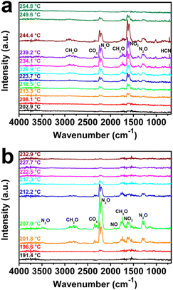 | ||
| Fig. 5 In situ FT-IR spectra of gaseous products during the thermal decomposition of (a) pure RDX and (b) RDX/SL-Co-ZIF-L. | ||
In addition, HCN (m/z = 27) is also observed as a product during the decomposition of pure RDX in the mass spectrum (Fig. S6†). Nevertheless, the peak is almost invisible for RDX/SL-Co-ZIF-L, which is consistent with the IR spectra. Combined with the results of FT-IR spectra, it can be concluded that after the import of SL-Co-ZIF-L, the main gaseous products during the decomposition of RDX will transform from NO2 and HCN into N2O and CH2O. It is a consensus that the initial decomposition of RDX is a competition of N–N fission and C–N fission,13,51–53 and the corresponding characteristic products are quite different, shown, respectively, as eqn (3) and (4):
| RDX → HCN + HONO | (3) |
| RDX → CH2O + N2O | (4) |
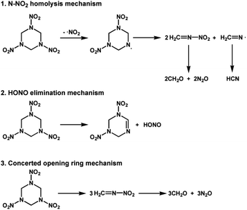
To be specific, the mechanisms characterized by N–N fission mainly include the N–NO2 homolysis mechanism and HONO elimination mechanism, where the characteristic products are HCN/HONO, while the mechanism characterized by C–N fission mainly refers to the concerted ring opening mechanism, where the characteristic products are N2O/CH2O (Scheme 1). During the N–N fission pathway, NO2 can also be produced from quick decomposition of HONO, shown as eqn (5).13,52
| 2HONO → NO2 + NO + H2O | (5) |
As a consequence, N–N fission is dominant during the decomposition of pure RDX, judging from the main gaseous products, while C–N fission is dominant when SL-Co-ZIF-L is added. Another evidence is the enhanced heat release of RDX/SL-Co-ZIF-L (2245 J g−1) compared with pure RDX (1489 J g−1). As shown in eqn (3) and (4), N–N fission is an endothermic reaction, while C–N fission is exothermic. Thus there will be more heat released if C–N fission is dominant. It has to be pointed out that N–NO2 homolysis and HONO elimination mechanisms often occupy the leading status under low-pressure and high-temperature conditions, especially in the gas-phase decomposition of RDX.51,54 Considering that the decomposition of RDX usually begins after the fusion process and RDX is easy to vaporize, the N–N fission should be the dominant decomposition pathway in most cases.51,53–55 Even for RDX in the crystal phase, there have been theoretical calculations proving that HONO elimination is the most favourable initial decomposition pathway owing to the lowest reaction barrier.51 Conversely, C–N fission might only dominate during the decomposition of RDX in the condensed phase, which is relatively infrequent in relevant literature studies. Therefore, it is quite interesting that the decomposition of RDX/SL-Co-ZIF-L mainly follows the C–N fission pathway. Nevertheless, it is worth noting that the thermal decomposition of RDX takes place before melting when SL-Co-ZIF-L is added, which has been inferred from the disappeared melting peak in the DSC curve (Fig. 4). This phenomenon exactly coincides with the mechanism analyses above. The decomposition of RDX in RDX/SL-Co-ZIF-L can take place early in the condensed phase (including the crystal phase), thus probably following the C–N fission mechanism.
From the analyses above, it is rational to speculate that the addition of SL-Co-ZIF-L can activate the condensed RDX and change the thermal decomposition mechanism from N–N fission to C–N fission. But there still remains the question why SL-Co-ZIF-L can exhibit far superior catalytic capability to ZIF-67. As shown in Fig. S7,† the in situ FT-IR spectra of gaseous products during the thermal decomposition of RDX/ZIF-67 reveal the feature which is intermediate between pure RDX and RDX/SL-Co-ZIF-L. In other words, the main gaseous products during the decomposition of RDX/ZIF-67 contain more N2O and CH2O rather than NO2 and HCN (peak height ratio of N2O/NO2 is 0.90) compared with pure RDX, indicating that the decomposition pathway of RDX begins to transform from N–N fission to C–N fission after the introduction of ZIF-67. This phenomenon is also in accordance with the intermediate decomposition peak reflected in the DSC curves (Fig. 4). Nevertheless, on the one hand, SL-Co-ZIF-L and ZIF-67 almost have the same chemical compositions and surface Co species, as reflected by the aforementioned characterization. On the other hand, ZIF-67 with a submicro-sized and well-dispersed morphology shows a much larger BET surface area and total pore volume than the micro-sized SL-Co-ZIF-L. So it is spontaneous to treat ZIF-67 as a better catalyst on account of the more exposed catalytically active sites. However, the current fact is surprisingly opposite.
Knocking out the factors of chemical composition, surface Co species and specific surface area, it is now necessary to give a deep insight into the different crystalline structures of ZIF-67 and Co-ZIF-L. Although ZIF-67 with a 3D porous structure has a much larger surface area, its rigid construction and narrow micropores (Fig. S8†) make it difficult to accommodate the large RDX molecule with a six-membered heterocyclic ring and extended N–NO2 groups. This hinders the contact between RDX and the internal structure of ZIF-67, thus making these micropores “useless” and leading to the sharp decrease of accessible active sites during the thermal decomposition processes. On the contrary, Co-ZIF-L has a 2D layered structure, which is different from ZIF-67 with a 3D sodalite topology, just like the relationship between Zn-ZIF-L and ZIF-8.42,43 Specifically, the 2D layers of Co-ZIF-L are part of the sodalite topology found in the 3D structure of ZIF-67 (Fig. S9†). The adjacent 2D layers are mainly stabilized by two types of interactions. One is the hydrogen bonds between terminal 2-MI ligands and the “free” 2-MI between the layers, and the other is the interactions between “free” 2-MI and another parallel 2-MI in the neighbouring layer (Fig. S10†). As a consequence, it is predictable that such weak interactions will be easily broken upon heating during the testing process of catalytic thermal decomposition of RDX. Thus the 2D layers of Co-ZIF-L will be separated and exposed to RDX molecules and reaction intermediates, which means that the originally “hidden” catalytic sites will be largely accessible to some extent. In a word, although SL-Co-ZIF-L has a smaller specific area and also narrow micropores under general conditions, the true catalytically active sites of SL-Co-ZIF-L in the dynamic testing environment are more than ZIF-67 instead.
From another perspective, SL-Co-ZIF-L was prepared in pure H2O at room temperature. Therefore, the coordination sites of Co2+ in SL-Co-ZIF-L were likely to be occupied by some weakly coordinated H2O molecules.56,57 This can be inferred from TG-DTG analyses to a certain extent. In the TG-DTG curves of ZIF-67 (Fig. S11†), it is clear that ZIF-67 shows a slow weight loss between 92 °C and 185 °C, which is mainly ascribed to the loss of residual H2O and organic species. In contrast, SL-Co-ZIF-L persistently loses weight in the higher temperature range until the first sharp loss starting at 234 °C (Fig. S4†), with a DTG peak at 181 °C, which is also higher than that of ZIF-67 (162 °C). In addition, the weight loss of SL-Co-ZIF-L at this stage is also more than that of ZIF-67 although its surface area is much smaller. These mean that SL-Co-ZIF-L might contain some coordinated H2O molecules in addition to the easily removed adsorbed H2O. So it can be predicted that the coordinated H2O molecules will be removed with the elevated temperature during the catalytic decomposition process of RDX, thus leading to the exposure of some unsaturated coordination sites. To illustrate the impact of coordination sites of Co-ZIFs towards their catalytic activity and mechanism, DFT calculations were further conducted. For the sake of simplifying computational models, the normal four-coordinated Co2+ was used to represent ZIF-67, while Co2+ coordinated by two 2-MI molecules was selected to represent Co-ZIF-L with unsaturated coordination sites. For the initial decomposition process of pure RDX (shown in Fig. 6a), the reaction barrier for the N–N fission pathway is calculated to be 1.97 eV and the corresponding free energy of the final state is 1.91 eV; both are much lower than those for the C–N fission pathway (3.15 eV and 2.86 eV, respectively). This is consistent with existing literature studies and the general understanding that N–N fission is more advantageous in most cases.51,53–55 When ZIF-67 is used as the catalyst, the four-coordinated Co2+ will become a catalytic site that can activate both C–N fission and N–N fission processes. To be specific, after the adsorption and activation effect of ZIF-67, the activation energy of the N–N fission pathway will be lowered by 1.39 eV (from 1.97 eV to 0.58 eV), while the activation energy of the C–N fission pathway will also be reduced from 3.15 eV to 1.84 eV (Fig. S12†). What is more, the final state for both N–N fission and C–N fission pathways can be stabilized by ZIF-67. Nevertheless, the reaction priority is not changed, which means that the N–N fission pathway is still the more advantageous pathway. However, when Co-ZIF-L is used as the catalyst, the unsaturated coordination sites will become a totally different active site. After the activation effect of Co-ZIF-L, the C–N bond is stretched from 1.47 Å to 1.66 Å, which means that the C–N bond is sufficiently activated and easy to break. Moreover, the energy changes during the N–N or C–N fission pathway are distinctly different from the above two situations. As revealed from Fig. 6b, although the reaction barrier of N–N fission pathway is reduced from 1.97 eV to 0.31 eV when using Co-ZIF-L as the catalyst, the reaction barrier of the C–N fission pathway is largely reduced from 3.15 eV to 0.22 eV, indicating that C–N fission seems to be more dominant than N–N fission. In addition, the final state energy of the C–N fission pathway (−2.93 eV) is also lower than that of the N–N fission pathway (−2.88 eV). This reversal makes C–N fission a more dominant pathway from the perspective of free energy, which is in accordance with the results of catalytic decomposition experiments above and confirms the unique role of SL-Co-ZIF-L as a superior catalyst for the thermal decomposition of RDX by facilitating the generally disadvantageous C–N fission pathway.
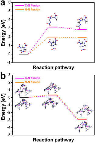 | ||
| Fig. 6 Free energy for N–N fission and C–N fission decomposition pathways of (a) pure RDX and (b) RDX/SL-Co-ZIF-L. | ||
Conclusions
In conclusion, star-like Co-ZIF-L (SL-Co-ZIF-L) with a micron size was synthesized through a room-temperature and aqueous-phase reaction, which exhibited unprecedented catalytic capability for the thermal decomposition of RDX. Concretely, SL-Co-ZIF-L can lower the decomposition temperature of RDX by 42.9 °C and boost the heat release by 50.8%, which is superior to most ever-reported catalysts including energetic MOFs. Interestingly, SL-Co-ZIF-L also showed far better performances than ZIF-67, which has almost the same chemical compositions but a much larger surface area. In-depth mechanism study from both experimental and theoretical perspectives reflects the reasons that the import of SL-Co-ZIF-L with a weakly interacted 2D structure could not only expose more catalytically active sites by the heating effect during the catalytic process, but also activate the exothermic C–N fission pathway for the decomposition of RDX in the condensed phase, thus reversing the commonly advantageous N–N fission pathway and promoting the decomposition process in the low-temperature stage. Our research reflects and dissects the abnormal catalytic performance of micro-sized MOF catalysts with a 2D layered structure, which will provide guidance for the rational structure design of catalysts used in micromolecule transformation reactions, e.g., the thermal decomposition of energetic materials.Conflicts of interest
There are no conflicts to declare.Acknowledgements
We greatly appreciate the financial support from the National Natural Science Foundation of China (No. 22105156).References
- T. An, F. Q. Zhao, Q. L. Yan, Y. J. Yang, Y. J. Luo, J. H. Yi and W. L. Hong, Propellants, Explos., Pyrotech., 2018, 43, 1087–1095 CrossRef CAS.
- F. Zhen, X. Y. Zhou, L. Q. Wang, R. J. Yang and F. L. Huang, Propellants, Explos., Pyrotech., 2019, 44, 362–368 CrossRef CAS.
- L. Liang, X. Guo, Z. Liang and G. Li, J. Energ. Mater., 2018, 36, 339–351 CrossRef CAS.
- D. R. Kshirsagar, S. Jain, S. N. Jawalkar, N. H. Naik, S. Pawar and M. Maurya, Propellants, Explos., Pyrotech., 2016, 41, 304–311 CrossRef CAS.
- W. Wang, T. Wei, H. Gao, L. Xiao, K. Xu and F. Zhao, Chin. J. Explos. Propellants, 2017, 40, 29–35 Search PubMed.
- T. Wei, Y. Zhang, K. Xu, Z. Ren, H. Gao and F. Zhao, RSC Adv., 2015, 5, 70323–70328 RSC.
- W. Q. Pang, L. T. DeLuca, X. Z. Fan, O. G. Glotov, K. Wang, Z. Qin and F. Q. Zhao, Combust. Flame, 2020, 220, 157–167 CrossRef CAS.
- F. Zhen, X. Y. Zhou, L. Q. Wang, R. J. Yang and F. L. Huang, Propellants, Explos., Pyrotech., 2019, 44, 362–368 CrossRef CAS.
- H. Li, B. Liu, Y. Xu, C. Wang, Z. Sun, H. Li, E. Yao, J. Yi, Z. Qin and F. Zhao, J. Anal. Appl. Pyrolysis, 2021, 157, 105228 CrossRef CAS.
- D. W. Ren, M. S. Wei, J. H. Shi, B. D. Wu, Y. Li and J. Y. Wang, Z. Anorg. Allg. Chem., 2021, 648, e202100106 Search PubMed.
- J. Shen, Z. Liu, B. Xu, F. Chen, Y. Zhu, Y. Fu, D. J. Kline, X. Liao and Z. Wang, J. Energ. Mater., 2020, 38, 326–335 CrossRef CAS.
- J. Shen, Z. Liu, B. Xu, H. Liang, Y. Zhu, X. Liao and Z. Wang, Propellants, Explos., Pyrotech., 2019, 44, 355–361 CrossRef CAS.
- R. Xu, L. Yang, H. Fang, Z. Mi, Y. Lv, L. Jiang, X. Fu, J. Li and G. Zhang, ACS Appl. Nano Mater., 2022, 5, 14942–14953 CrossRef CAS.
- J. Wang, X. Lian, S. Chen, H. Li and K. Xu, J. Colloid Interface Sci., 2022, 610, 842–853 CrossRef CAS PubMed.
- J. Wang, X. Lian, Q. Yan, D. Gao, F. Zhao and K. Xu, ACS Appl. Mater. Interfaces, 2020, 12, 28496–28509 CrossRef CAS PubMed.
- S. Hanafi, D. Trache, W. He, W. X. Xie, A. Mezroua and Q. L. Yan, J. Phys. Chem. C, 2020, 124, 5182–5195 CrossRef CAS.
- H. Mei, Y. Xu, G. Lei, W. Cao, Z. Li and J. Zhang, New J. Chem., 2022, 46, 1687–1692 RSC.
- C. Y. Wu, Y. C. Chen, T. H. Wang, C. I. Lin, C. W. Huang and S. R. Zhou, Combust. Flame, 2021, 232, 111556 CrossRef CAS.
- J. Zhang, B. Jin, X. Li, W. Hao, T. Huang, B. Lei, Z. Guo, J. Shen and R. Peng, Chem. Eng. J., 2021, 404, 126287 CrossRef CAS.
- Y. Liu, S. Jin, H. Yang, S. Li, W. Xie, Y. Zhao, W. Zhang, Y. Chen and X. Fan, Combust. Flame, 2021, 225, 57–64 CrossRef CAS.
- M. Rimoldi, A. J. Howarth, M. R. DeStefano, L. Lin, S. Goswami, P. Li, J. T. Hupp and O. K. Farha, ACS Catal., 2017, 7, 997–1014 CrossRef CAS.
- A. J. Howarth, Y. Liu, P. Li, Z. Li, T. C. Wang, J. T. Hupp and O. K. Farha, Nat. Rev. Mater., 2016, 1, 15018 CrossRef CAS.
- Y. Yang, Y. Bai, F. Zhao, E. Yao, J. Yi, C. Xuan and S. Chen, RSC Adv., 2016, 6, 67308–67314 RSC.
- J. Yan, H. Wang, B. Jin, M. Zeng and R. Peng, J. Solid State Chem., 2021, 297, 122060 CrossRef CAS.
- Y. Huang, R. Peng and B. Jin, New J. Chem., 2021, 45, 11068–11074 RSC.
- S. Wu, M. Li, Z. Yang, Z. Xia, B. Liu, Q. Yang, Q. Wei, G. Xie, S. Chen, S. Gao and J. Y. Lu, Green Chem., 2020, 22, 5050–5058 RSC.
- Q. Yang, G. Yang, W. Zhang, S. Zhang, Z. Yang, G. Xie, Q. Wei, S. Chen and S. Gao, Chem. - Eur. J., 2017, 23, 9149–9155 CrossRef CAS PubMed.
- S. Wu, G. Lin, Z. Yang, Q. Yang, Q. Wei, G. Xie, S. Chen, S. Gao and J. Y. Lu, New J. Chem., 2019, 43, 14336–14342 RSC.
- X. Ma, Y. Liu, W. Song, Z. Wang, X. Liu, G. Xie, S. Chen and S. Gao, Dalton Trans., 2018, 47, 12092–12104 RSC.
- Q. Yang, X. Song, W. Zhang, L. Hou, Q. Gong, G. Xie, Q. Wei, S. Chen and S. Gao, Dalton Trans., 2017, 46, 2626–2634 RSC.
- X. Qu, Q. Yang, J. Han, Q. Wei, G. Xie, S. Chen and S. Gao, RSC Adv., 2016, 6, 46212–46217 RSC.
- Y. Liu, P. Yi, L. Gong, X. Yi, P. He, T. Wang and J. Zhang, Inorg. Chem., 2023, 62, 3186–3194 CrossRef CAS PubMed.
- C. Liang, J. Yang, Y. Guo, F. Yuan, W. Song, J. Xi, X. Liu and S. Chen, Inorg. Chem., 2021, 60, 9282–9286 CrossRef CAS PubMed.
- S. Cao, X. Ma, X. Ma, P. Cen, Y. Wu, J. Yang, X. Liu, G. Xie and S. Chen, Dalton Trans., 2020, 49, 2300–2307 RSC.
- J. Zhao, X. Li, M. Zhang, Z. Xu, X. Qin, Y. Liu, L. Han and G. Li, Nanoscale, 2023, 15, 4612–4619 RSC.
- H. Zhang, S. Wang, M. Wang, G. Li, L. Yu, X. Liu, Z. Wang and C. Zhang, J. Rare Earths, 2022 DOI:10.1016/j.jre.2022.12.006.
- J. Wang, Y. Li, S. Xu, C. Lin, X. Ma, Y. Ni and S. Cao, New J. Chem., 2022, 46, 2962–2970 RSC.
- K. Wang, S. Liu, Y. Li, G. Wang, M. Yang and Z. Jin, Appl. Surf. Sci., 2022, 601, 154174 CrossRef CAS.
- J. Mor, S. K. Sharma, P. Utpalla, J. Bahadur, J. Prakash, A. Kumar and P. K. Pujari, Microporous Mesoporous Mater., 2022, 335, 111814 CrossRef CAS.
- Y. He, Z. Abedi, C. Ni, S. Milliken, K. M. O'Connor, D. G. Ivey and J. G. C. Veinot, ACS Appl. Nano Mater., 2022, 5, 12496–12505 CrossRef CAS.
- B. Zhang, H. Xu, Q. Chen, H. Chen and G. He, J. Alloys Compd., 2022, 922, 166216 CrossRef CAS.
- J. Zhang, T. Zhang, D. Yu, K. Xiao and Y. Hong, CrystEngComm, 2015, 17, 8212–8215 RSC.
- R. Chen, J. Yao, Q. Gu, S. Smeets, C. Baerlocher, H. Gu, D. Zhu, W. Morris, O. M. Yaghi and H. Wang, Chem. Commun., 2013, 49, 9500–9502 RSC.
- M. Wang, J. Liu, C. Guo, X. Gao, C. Gong, Y. Wang, B. Liu, X. Li, G. G. Gurzadyana and L. Sun, J. Mater. Chem. A, 2018, 6, 4768–4775 RSC.
- N. T. Tran, L. G. Trung and M. K. Nguyen, J. Solid State Chem., 2021, 300, 122287 CrossRef CAS.
- M. Jafarinasab, A. Akbari, M. Omidkhah and M. Shakeri, Energy Fuels, 2020, 34, 12779–12791 CrossRef CAS.
- X. Song, S. Zhang, G. Zhao, W. Zhang, D. Chen, Q. Yang, Q. Wei, G. Xie, D. Yang, S. Chen and S. Gao, RSC Adv., 2016, 6, 93231–93237 RSC.
- W. Gao, X. Liu, Z. Su, S. Zhang, Q. Yang, Q. Wei, S. Chen, G. Xie, X. Yang and S. Gao, J. Mater. Chem. A, 2014, 2, 11958–11965 RSC.
- J. J. Liu, Z. L. Liu, J. Cheng and D. Fang, J. Solid State Chem., 2013, 200, 43–48 CrossRef CAS.
- G. T. Long, S. Vyazovkin, B. A. Brems and C. A. Wight, J. Phys. Chem. B, 2000, 104, 2570–2574 CrossRef CAS.
- Y. Ma, M. Lv, F. Shang, C. Zhang, J. Liu and P. Zhou, J. Phys. Chem. A, 2022, 126, 1666–1673 CrossRef CAS PubMed.
- C. Wan, J. Li, S. Chen, W. Wang and K. Xu, J. Anal. Appl. Pyrolysis, 2021, 160, 105372 CrossRef CAS.
- X. Chen and C. F. Goldsmith, Proc. Combust. Inst., 2019, 37, 3167–3173 CrossRef CAS.
- R. W. Molt Jr., T. Watson Jr., A. P. Bazanté, R. J. Bartlett and N. G. J. Richards, Phys. Chem. Chem. Phys., 2016, 18, 26069–26077 RSC.
- M. J. Swadley and T. Li, J. Chem. Theory Comput., 2007, 3, 505–513 CrossRef CAS PubMed.
- Z. Zou, T. Wang, X. Zhao, W. J. Jiang, H. Pan, D. Gao and C. Xu, ACS Catal., 2019, 9, 7356–7364 CrossRef CAS.
- H. G. Hao, Y. F. Zhao, D. M. Chen, J. M. Yu, K. Tan, S. Ma, Y. Chabal, Z. M. Zhang, J. M. Dou, Z. H. Xiao, G. Day, H. C. Zhou and T. B. Lu, Angew. Chem., Int. Ed., 2018, 57, 16067–16071 CrossRef CAS PubMed.
Footnote |
| † Electronic supplementary information (ESI) available: Experimental section, SEM images, FT-IR spectra, XPS spectra, TG-DTG curves, DSC curves, MS curves, crystal structure, micropore size distribution curve, free energy for different decomposition pathways and Tables S1 and S2. See DOI: https://doi.org/10.1039/d3ra01551c |
| This journal is © The Royal Society of Chemistry 2023 |

