 Open Access Article
Creative Commons Attribution 3.0 Unported Licence
Strong attractive interaction between finite element models of twisted cellulose nanofibers by intermeshing of twists†
Kojiro Uetani *a and
Takuya Uto
 b
b
aDepartment of Industrial Chemistry, Faculty of Engineering, Tokyo University of Science, 6-3-1 Niijuku, Katsushika-ku, Tokyo 125-8585, Japan. E-mail: uetani@ci.tus.ac.jp
bGraduate School of Engineering, University of Miyazaki, Nishi 1-1 Gakuen Kibanadai, Miyazaki 889-2192, Japan. E-mail: t.uto@cc.miyazaki-u.ac.jp
First published on 31st May 2023
Abstract
Analysis of the attractive interaction between intrinsically twisted cellulose nanofibers (CNFs) is essential to control the physical properties of the higher-order structures of CNFs, such as paper and spun fiber. In this study, a finite element model reflecting the typical morphology of a twisted CNF was used to analyze the attractive interaction forces between multiple approaching CNF models. For two parallel CNF models, when one of the CNF models was rotated 90° around the long-axis direction, the twisting periods meshed, giving the maximum attraction force. Conversely, when the two CNF models were approaching diagonally, the CNF models were closest at an angle of −3.2° (i.e., in left-handed chirality) to give the most stable structure owing to the right-handed twist of the CNF models themselves. Furthermore, the two nematic layers were closest when one nematic layer was approached at an angle of −2° (i.e., in left-handed accumulation chirality), resulting in the greatest attraction. The results characterize the unique distribution of the attractive interaction forces between twisted CNF models, and they underscore the importance of chiral management in CNF aggregates, especially intermeshing of twists.
1. Introduction
A material composed of accumulated plant fibers that self-agglutinate by hydrogen bonding and dispersion attraction is generally defined as paper. The physical properties of paper, such as the mechanical strength, are largely dependent on the attractive interaction (i.e., the adhesive force) between the fibers, in addition to shape factors, such as the length and thickness of the constituent fibers. For example, micron-size pulp fibers are generally paper made through beating and refining, which adjusts the accumulation structure by changing the fiber morphology and controls the properties of the paper by the degree of adhesion. In other words, understanding the relationship between the accumulation structure and its attractive interaction is essential for controlling the properties of paper materials.Cellulose nanofibers (CNFs) obtained by nanofibrillation of wooden pulp fibers can be filtered and dried in the same way as pulp fibers to give paper.1 A wooden CNF is a crystalline fiber consisting of approximately 18 linear cellulose molecular chains,2,3 and unlike pulp fibers, it must be used without artificially changing its morphology (swelling or dissolving) so as to not destroy the high functionality of its extended-chain crystal structure. Therefore, the morphology of CNFs, and the attractive interaction, which depends on their accumulation structure, are directly related to the physical properties of the nanopaper. Although the resultant structures that can experimentally form (random, partial nematic, or uniaxially aligned structures) have been investigated,4,5 few systematic analyses of the interaction forces, which vary with the accumulation mode, have been performed.
One of the factors that makes analysis of the interaction forces between CNFs difficult is the twisted morphology of CNFs. Fibrillated single CNFs exhibit a gentle right-handed twist,6–8 and wooden CNFs have been reported to have a twisting period of ∼232 nm.9 The twisting period can be varied by drying the CNFs on a flat substrate7 or by changing the surface charge density.10 Toward characterizing the interaction forces in complex CNF aggregates, it is important to first understand the interaction forces that arise when two structural models of typical twisted CNFs approach each other. However, there has been little analysis of the interaction forces considering the twisted morphology of CNFs, either experimentally or computationally.
Cellulose nanocrystals (CNCs), highly crystalline needle-like short fibers, are produced by acid hydrolysis of plant pulp to remove amorphous parts. When twisted CNFs or CNCs concentrate in water, they self-organize into cholesteric liquid-crystal structures with helically stacked aligned layers.11,12 Drying of this liquid crystal narrows the nematic layer spacing in the thickness direction, resulting in a paper that maintains partial chirality.13 The formation principle of cholesteric liquid crystals has been characterized by the entropy,14,15 crystallite bundles for CNCs,16 steric and electrostatic interactions between chiral viruses,17 and screw-like rod threads engaging with each other,14,18 but there have been few analyses of the short-range attractive interaction energy assuming dense CNF films after removing/drying the dispersion medium. Films made of CNFs or CNCs with a nematic-ordered structure have been reported to have better physical properties, such as higher density, higher mechanical strength, higher thermal conductivity, and lower gas permeability, than films without a nematic structure.4,19,20 A prominent example is the better mechanical properties exhibited by Bouligand structures in biological tissues.21–23 However, it is very difficult to experimentally determine if the good physical properties of cholesteric structures are due to their unique fiber orientation or special attractive interaction forces based on the accumulation chirality. To characterize hierarchical fiber-accumulated CNF materials, such as cholesteric structures, toward pioneering control guidelines for physical properties, it is important to elucidate the interaction force distributions for structures in which multiple twisted CNFs are oriented or close to each other at various angles.
The objective of this study is to characterize bundling and cholesteric accumulation structures in terms of the interaction energies based on the geometry of the twisted CNFs. A finite element model of a twisted CNF was used to design an arbitrary CNF accumulation structure and calculate the total interaction energy. First, the bundling structure of two twisted CNF models was analyzed to determine the distribution of interaction forces exerted by the twisted geometry. Two circular nematic layers composed of multiple parallel twisted CNF models were then modeled, and the energies when the layers were approached at different angles were calculated. The simulations demonstrated that large accumulation stabilizing ability is only exhibited when the twisted CNF models form a specific left-handed chiral configuration.
2. Methods
The COMSOL model (COMSOL Multiphysics 5.5, COMSOL Inc., Stockholm, Sweden) reported in a previous study24 was used as the finite element model for the wooden twisted CNF. In brief, the hexagonal cross section of the 18-chained CNF model and its dimensions2 were formed on the yz plane and swept for a 360° right-handed twist for a sweep length of 232 nm9 in the x-axis direction. A tetrahedral physics-controlled mesh (the finest mesh automatically set by COMSOL, resulting mesh size of 0.0465–4.65 nm) was used.The surface planes of the CNF model surface corresponded to the CNF crystal planes, as shown in Fig. 1a. The interaction energy (U) between the nodes in each plane was defined by the shifted-force-type Lennard-Jones 12-6 potential function:
 | (1) |
 | (2) |
Differentiating eqn (1) with respect rij gives the force (F) acting between the nodes (assuming that the repulsive force is positive):
 | (3) |
| Rmin ≈ 21/6r0. | (4) |
Because rcutoff = 6r0, the second term in eqn (3) can be ignored. Substituting rij = Rmin into the second derivative of eqn (1) gives a positive value, confirming that U has the minimum value at Rmin and is in an energetically stable state. Therefore, this Rmin is in good agreement with the lattice constant of the material. Rmin, which gives the potential minimum point of U, was reasonably considered to be the distance between the crystal planes, and it was set for each face of the CNF model with reference to the crystal–structure parameters (Table 1). The spacing of the crystalline planes of cellulose Iβ27 was used for Rmin between the same crystalline planes. Rmin between dissimilar crystal planes was estimated by the additive average of each crystal-plane spacing (Lorentz–Berthelot combining rule). In the actual PE calculations, these Rmin values were converted to r0 by eqn (4) (Table 1). There is no information about the crystal-plane spacing for Rmin involving planes 1 and 8. Therefore, for the combination of plane 1 or 8 and hydrophilic plane 2, 3, 6, or 7, the average of the Rmin values for (1 1 0) × (1 1 0), (1 ![[1 with combining macron]](https://www.rsc.org/images/entities/char_0031_0304.gif) 0) × (1
0) × (1 ![[1 with combining macron]](https://www.rsc.org/images/entities/char_0031_0304.gif) 0), and (1 1 0) × (1
0), and (1 1 0) × (1 ![[1 with combining macron]](https://www.rsc.org/images/entities/char_0031_0304.gif) 0) was used. For the combination of plane 1 or 8 and hydrophobic planes 4 and 5, the average of the Rmin values for (1 1 0) × (2 0 0) and (1
0) was used. For the combination of plane 1 or 8 and hydrophobic planes 4 and 5, the average of the Rmin values for (1 1 0) × (2 0 0) and (1 ![[1 with combining macron]](https://www.rsc.org/images/entities/char_0031_0304.gif) 0) × (2 0 0) was used.
0) × (2 0 0) was used.
| Combination | ε (kJ mol−1) | r0 (nm) | Rmin (nm) |
|---|---|---|---|
| a–cEstimated by additive averaging of the intercrystalline plane distances at each constituent plane.a (0.53 + 0.60)/2 = 0.565.b (0.53 + 0.39)/2 = 0.46.c (0.60 + 0.39)/2 = 0.495. | |||
| (1 1 0) × (1 1 0) | 25.0 | 0.47 | 0.53 |
(1 ![[1 with combining macron]](https://www.rsc.org/images/entities/char_0031_0304.gif) 0) × (1 0) × (1 ![[1 with combining macron]](https://www.rsc.org/images/entities/char_0031_0304.gif) 0) 0) |
25.0 | 0.53 | 0.60 |
(1 1 0) × (1 ![[1 with combining macron]](https://www.rsc.org/images/entities/char_0031_0304.gif) 0) 0) |
25.0 | 0.50 | 0.565a |
| (2 0 0) × (2 0 0) | 75.0 | 0.35 | 0.39 |
| (1 1 0) × (2 0 0) | 1.0 | 0.41 | 0.46b |
(1 ![[1 with combining macron]](https://www.rsc.org/images/entities/char_0031_0304.gif) 0) × (2 0 0) 0) × (2 0 0) |
1.0 | 0.44 | 0.495c |
When eqn (1) and (4) are coupled, U(Rmin) ≈ −ε. Because U → 0 at the dissociation limit rij → rcutoff, ε corresponds to the binding energy between the nodes. The values of ε were taken from the parameters applied in coarse-grained CNF models at similar scales, taking into account the mesh size.28 Note that in this coarse-grained CNF model, it has been reported that the binding energy between two CNFs roughly reproduces the value evaluated by the all-atom model, so the parameters are thought to be highly reliable. By treating (1 1 0) and (1 ![[1 with combining macron]](https://www.rsc.org/images/entities/char_0031_0304.gif) 0) as equivalent planes, ε was determined to be 25, 75, and 1.0 kJ mol−1 for the combinations of hydrophilic/hydrophilic, hydrophobic/hydrophobic, and hydrophilic/hydrophobic surfaces, respectively. In this study, planes 2, 3, 6, and 7 were defined as hydrophilic surfaces and planes 4 and 5 were defined as hydrophobic surfaces. Planes 1 and 8 were also treated as hydrophilic surfaces, with ε depending on the combination of the constituent surfaces (Tables S1 and S2†).
0) as equivalent planes, ε was determined to be 25, 75, and 1.0 kJ mol−1 for the combinations of hydrophilic/hydrophilic, hydrophobic/hydrophobic, and hydrophilic/hydrophobic surfaces, respectively. In this study, planes 2, 3, 6, and 7 were defined as hydrophilic surfaces and planes 4 and 5 were defined as hydrophobic surfaces. Planes 1 and 8 were also treated as hydrophilic surfaces, with ε depending on the combination of the constituent surfaces (Tables S1 and S2†).
D denotes the distance between the centers of gravity of the CNF models/groups, and D in the x, y, and z directions is denoted Dx, Dy, and Dz, respectively. Min. PE represents the minimum PE.
For several CNF models in close proximity, the potential energy (U) between the nodes of each CNF model was summed to estimate the total interaction force (PE) in the accumulated structure. First, as shown in Fig. 2, condition (1) established the basic form of the CNF model and the first group with one or more CNF models. Condition (1) includes the coordinates of the center of gravity (x, y, z) of the model end face, the sweep length of the yz cross section in the x direction, the twist angle during the sweep, and the rotation angle around the sweep axis (x axis). The y and z axes pass through the center of gravity of the model/group. Next, condition (2) duplicates the first group. The parallel shift distances in the x, y, and z directions and the rotation angles around the x, y, and z axes passing through the center of gravity of the model/group are then set for the second group when both groups are placed close to each other. In other words, the accumulated structures that can be analyzed by this system are limited to relatively simple structures that duplicate the first group and adjust its arrangement. Finally, as condition (3), we used the potential functions and parameters set in eqn (1) and Table 1 (more specifically, Tables S1 and S2† for ε and r0). These conditions were loaded into a custom-made Matlab program commissioned to the KOBELCO Research Institute, Inc. (Kobe, Japan) to control COMSOL using LiveLink for Matlab (COMSOL Inc., Stockholm, Sweden). The total interaction forces (PEs) of the final accumulated structures were calculated with this program.
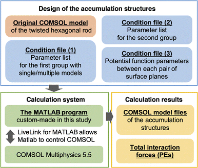 | ||
| Fig. 2 Relationship diagram of the system for designing the accumulation structures of twisted hexagonal CNF models and calculating their PEs. | ||
3. Results and discussion
3.1 Operation verification of the calculation system
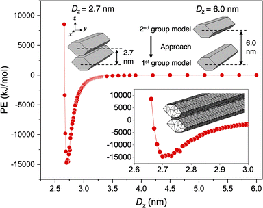
To verify that the constructed calculation system worked as configured, the approach behavior of two hexagonal prism CNF models with torsion removed from the CNF models was calculated. Planes 4 and 5 of the CNF models were set to approach each other with the parameters and settings in Table 1, and ε for all other planes was set to 0. The results of PE calculations for different distances between the centers of gravity of the two CNF models are shown in Fig. 3. PE, which was 0 kJ mol−1 at long distance, became negative as the distance decreased, indicating an attractive interaction between the CNF models. As the planes further approached each other, the repulsive force rapidly increased and diverged, giving a Lennard-Jones-type potential curve.For this CNF model, the PE plot tended to be somewhat scattered owing to the close intermodel distance relative to the nodal spacing and the irregular placement of the nodes. Therefore, to precisely calculate the Min. PE, OriginPro 2020 and 2021 (OriginLab Corp., MA, USA) were used to fit the PE plot (Fig. 3) according to
 | (5) |
The CNF model in Fig. 3 without torsion gave PE = −14![[thin space (1/6-em)]](https://www.rsc.org/images/entities/char_2009.gif) 921 kJ mol−1 at Dz = 2.71 nm. Because the thickness of the CNF model in the z direction was set to 2.34 nm, the distance between the CNF model surfaces for Min. PE was calculated to be 0.37 nm. This distance was close to the Rmin value (0.39 nm) set in Table 1. rcutoff was set to 3.2 nm, so the PE was 0 when Dz was greater than 5.54 nm. The above results reproduced the set parameters, confirming that the system can correctly perform the calculations.
921 kJ mol−1 at Dz = 2.71 nm. Because the thickness of the CNF model in the z direction was set to 2.34 nm, the distance between the CNF model surfaces for Min. PE was calculated to be 0.37 nm. This distance was close to the Rmin value (0.39 nm) set in Table 1. rcutoff was set to 3.2 nm, so the PE was 0 when Dz was greater than 5.54 nm. The above results reproduced the set parameters, confirming that the system can correctly perform the calculations.
3.2 Interaction force between two parallel twisting CNF models
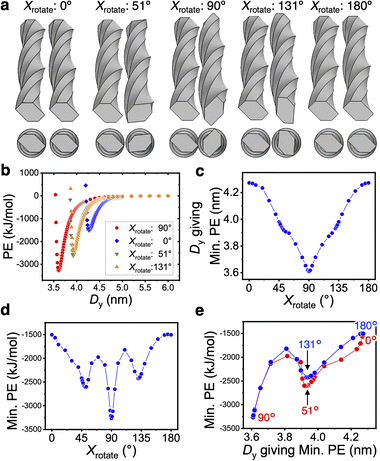
To investigate the relationship between the bundle structure of the two 232 nm-long twisted CNF models in Fig. 1 and their PE, the first CNF model on the left-hand side was fixed and the parallel second CNF model on the right-hand side (adjacent in the y-axis direction) was rotated around the x axis (long axis). The relationship between Min. PE and the distance Dy giving Min. PE was analyzed with respect to the rotation angle around the x axis (Xrotate) (Fig. 4).Dy was largest for Xrotate = 0° and 180°, and it was smallest for Xrotate = 90°. When Xrotate = 90°, the twisting periods of the left and right CNF models meshed and the structure allowed the CNF models to be closest (Fig. 4a). In this case, Min. PE was −3264 kJ mol−1, which was approximately twice the value for Xrotate = 0°, because the area in which the models could interact was maximized. For all of the Xrotate values, the dependence of Dy on PE resulted in smooth profiles (Fig. 4b), unlike the case of the untwisted CNF model in Fig. 3. The distribution of Dy from Xrotate = 0° to 180° was symmetrical around 90° (Fig. 4c). The distribution of Min. PE was also highly symmetric with respect to Xrotate (Fig. 4d). The local minima at ∼51° and ∼131° suggest the presence of a new metastable association structure. The nonlinear Min. PE distribution is considered to be because of the different parameters defined for each surface plane.
The interaction force distribution of the two parallel CNF models was exactly the same when the second CNF model was placed above the first CNF model (adjacent in the z-axis direction), as shown in Fig. S1.† When the CNF models were placed parallel to each other in the z-axis direction, the smallest PE was obtained for Xrotate = 90°. From this result, it can be concluded that the interaction force was correctly calculated regardless of the relative positions of the CNF models.
3.3 Most stable accumulation structure for two twisted CNF models with 90° difference in Xrotate
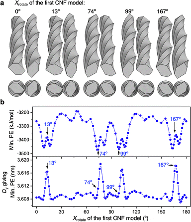
In Section 3.2, the first CNF model was fixed and only Xrotate of the second CNF model was varied, but a variety of relative configurations with a 90° difference in Xrotate between the CNF models can be taken. Therefore, we searched for the most stable structure by rotating the first CNF model around the x axis while maintaining a 90° difference in Xrotate with the second CNF model.The structure was constructed by varying Xrotate of the first CNF model and setting the x-axis rotation angle of the second model to Xrotate + 90°, as shown in Fig. 5a. In all cases, the torsion period of the CNF model was engaged, indicating that the CNF models were close together and the interaction forces were high. By plotting Min. PE and Dy against Xrotate for the first CNF model (Fig. 5b), we found that overall Dy was small and Min. PE (absolute value) was at a large level. However, they showed periodic fluctuations. Interestingly, at Xrotate when Dy was temporarily large, the absolute values of Min. PE became larger in the vicinity (approximately −3400 kJ mol−1 or greater). The relationship between Min. PE and Dy was clearly different at small Dy (approximately 3.61 nm or less) and at larger Dy (Fig. S2†). From the hexagonal edge lengths of the CNF cross section, it was inferred that the periodic appearance of surfaces with different widths temporarily increased the number of nodes that can interact, lowering Min. PE. Furthermore, a temporary increase in Dy and a temporary decrease in Min. PE (absolute value) occurred at the same Xrotate (Fig. 5b). It is considered that an increase in Dy would increase the distance between the CNF models, as a tradeoff for an increase in the interaction area, resulting in a slight decrease in Min. PE.
3.4 Diagonal proximity and interaction forces of two twisted CNF models
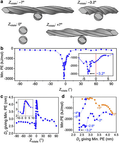
Min. PE and Dz with respect to the rotation angle Zrotate were evaluated when the centers of gravity of CNF models with Xrotate = 0° were placed on the same z axis and the first model (bottom side) was fixed and the second CNF model (top side) was rotated around the z axis with the center of gravity.When the 232 nm-long right-handed-twist CNF model approached at an angle, the direction of the twist directly affected the approach distance (Fig. 6a). For large positive and negative Zrotate values (absolute values greater than ∼7°), the contact area was small and the interaction force was weak (Fig. 6b). Conversely, when the absolute value of Zrotate was small, the asymmetry caused by the twisting direction of the CNF model was clearly expressed.
When Zrotate was negative, the chirality of the two-model configuration was left-handed, showing a maximum Min. PE (absolute value) of −2987 kJ mol−1 at Zrotate = −3.2°. This local attraction was approximately 15 times larger than that at Zrotate = ±(30–90)°. In particular, when Zrotate was approximately −2.6° to −3.3°, the right-handed twists of the CNF models meshed with each other, the CNF models more closely approached (Dz became smaller), and their Min. PE became smaller than −2500 kJ mol−1 (Fig. 6c and d). We confirm that the accumulation mode of the twisted CNF model is consistent with the prediction derived from entropy14,18 that screw-like rods pack tightly by interlocking threads along grooves.
For calculations with Zrotate = −3.2° to −5°, as Dz decreased, the CNF models overlapped before the PE reached the local minimum PE, making calculations with small Dz impossible. Therefore, the smallest PE value in the calculated range was used, and at that time the Dz values were all 2.35 nm (Fig. 6c). When Zrotate = −3.2° to −5°, planes 4 and 5 defined in Fig. 1 are considered to be mainly approaching each other. Taking into account the z-direction thickness of the CNF model of 2.34 nm, the distance between the surfaces approaches a distance below Rmin, so the occurrence of local repulsion can be inferred. Nevertheless, the attractive Min. PEs for the entire system were still dominant at Zrotate = −3.2° to −5°. We speculate that in oblique approach at the small and negative Zrotate, the various surface and nodal combination are at the distances that exhibit attractive interactions.
When Zrotate was positive, Dz tended to be larger because the right-handed twists of the CNF models did not engage and the convexities were closer together (Fig. 6c). The resulting Min. PE (absolute value) was smaller and the Min. PE distribution was completely asymmetric with respect to the negative Zrotate case (Fig. 6b and d). This result was the opposite of the parallel CNF model shown in Fig. 4 and 5.
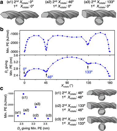
3.5 Effect of Xrotate at Zrotate = −3.2°
Within the oblique approach of the two CNF models, Zrotate of the second CNF model was fixed at −3.2° and the Min. PE distribution was evaluated by varying Xrotate of the second CNF model, while that of first CNF model was fixed at 0°. Local minima of Min. PE occurred when Xrotate of the second CNF model was 0°, 46°, and 133° (Fig. 7). In the lower first CNF model, plane 5 was mainly in close proximity to the upper CNF model near the center of gravity. Conversely, the upper second CNF model was closest to the lower CNF model mainly for plane 4 when Xrotate = 0°, for plane 6 when Xrotate = 46°, and for plane 7 when Xrotate = 133°. From Tables 1, S1, and S2,† the combination of planes 4 and 5 (when Xrotate = 0°) has the largest ε and smallest Rmin (r0), and the result is reasonable given the largest Min. PE (absolute value) in Fig. 7. The combinations of planes 5 and 6, and 5–7 (Xrotate = 46° and 133°, respectively) both have the smallest ε, and Rmin (r0) is smaller for planes 5 and 6. The effect is directly seen in the smaller Dz for Xrotate = 46° in Fig. 7b. Although the interaction forces owing to other surfaces are of course included, it is clearly shown that the interaction force was the largest when the approaching surfaces were parallel to each other.Changing Xrotate of the first CNF model, which was fixed at 0°, 46°, and 133°, was considered to change the proximity plane to the second CNF model. Therefore, we investigated Min. PE for six combinations of Xrotate ((a1)–(a3) in Fig. 7a and (c1)–(c3) in Fig. 7c). The structure (c3) became stable with the largest Min. PE (absolute value), while (c1) became unstable with the smallest Min. PE (Fig. 7c). In structure (c1), planes 3 and 6 were the closest to each other, and in (c3), planes 2 and 7 were the closest to each other, which both correspond to combinations of hydrophilic surfaces of the CNF. The intermodel distance for (c1) was close with Dz = ∼2.6 nm, while Dz for (c3) was the largest among the six CNF models (Dz = ∼3.6 nm).
The maximum interaction force at Zrotate = −3.2° for the second CNF model was −3230 kJ mol−1, as indicated by only (c3). In Fig. 7b, Min. PEs above −2000 kJ mol−1 were obtained at many Xrotate values, and only the limited structures had more stable Min. PE. On the other hand, in Fig. 5, most structures showed −3200 to −3500 kJ mol−1 regardless of the Xrotate value, indicating that the parallel bundling at Xrotate = 90° (at Zrotate = 0°) is more stable than the diagonal approach in Fig. 7 for two twisted CNF models above this length (≧232 nm).
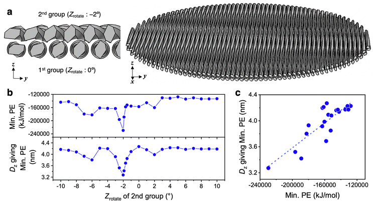
3.6 Most stable structure with two nematic layers
Two circular nematic layers with multiple twisted CNF models aligned in parallel were modeled to evaluate the interaction energy when the layers approached at different rotation angles. Within the nematic layer, n CNF models were arranged in a circular shape with a diameter of 232 nm, parallel to the x axis and lineally symmetric with the x axis as the axis of symmetry to preserve the rotational symmetry around the z axis (the detailed design is described in Appendix 1). The twisted CNF models were placed in a single nematic layer with the same relative arrangement as in Fig. 4a with Xrotate = 0°. Dy = 4.27253 nm, which gives Min. PE, was used, and the resulting structure with 54 CNF models circularly arranged in one nematic layer was designed (Fig. 8a). The first layer (the first group) was duplicated in the z-axis direction to form the second group, and Min. PE and Dz (in this case, the distance between the centers of gravity of each group) were calculated when both groups approached relative to the rotation angle around the z axis with the center of gravity of the second group (Zrotate).The distribution of Min. PE and Dz was asymmetric with respect to Zrotate = 0°, and when Zrotate = −2° for the second group, Min. PE and Dz were the lowest (Fig. 8b). At Zrotate = −2°, Min. PE was −229![[thin space (1/6-em)]](https://www.rsc.org/images/entities/char_2009.gif) 660 kJ mol−1, which was approximately 1.6 times higher in absolute value than at positive Zrotate (approximately −140
660 kJ mol−1, which was approximately 1.6 times higher in absolute value than at positive Zrotate (approximately −140![[thin space (1/6-em)]](https://www.rsc.org/images/entities/char_2009.gif) 000 kJ mol−1). In the approach of the nematic layers, as in the case of the two CNF models (Fig. 6 and 7), the most stable structure was the one that accumulated in the left-handed direction.
000 kJ mol−1). In the approach of the nematic layers, as in the case of the two CNF models (Fig. 6 and 7), the most stable structure was the one that accumulated in the left-handed direction.
Min. PE and Dz were roughly correlated with the slope of the fitted line was found to be 9.59 × 10⁻⁶ (nm (kJ mol−1)−1) (R2 = 0.74) (Fig. 8c), indicating that the “layer-to-layer approachability,” which depends on the twisting period of the CNF model and the intermodel distance within a nematic layer, was directly related to the interaction force. Min. PE (absolute value) was larger in the chiral integration case (Zrotate = −2°) than in the case where the nematic layers were perfectly parallel (Zrotate = 0°, i.e., the uniaxially aligned structure). In dried films containing the nematic structure, the angle between the layers was found to play an important role in the fiber-packing structure and interaction forces.
4. Conclusions
A finite element model of a twisted CNF has been used to investigate the relationship between the accumulation structure and the attractive interaction. For two parallel CNF models with the long axis along the x axis, when one of the CNF models had Xrotate = 90°, the torsion periods intermeshed and showed twice the attraction force when Xrotate = 0°. Conversely, when the two CNF models approached diagonally (rotated around the z axis), Min. PE was asymmetric with respect to positive and negative Zrotate, and it was most stable at negative Zrotate (−3.2° to the left), showing 15 times larger attraction force than at larger angles. This tendency for left-handed accumulation chirality was also found for the attraction force in the proximity of two nematic layers, and it was found that the layers were the closest when the Zrotate of the second layer was −2°, giving 1.6 times larger attraction force than at positive Zrotate.The interaction calculation using the finite element twisted CNF model analyzes very short distances assuming dry conditions without a dispersion medium, ignoring the effect of moisture to which real CNFs are often exposed. However, the accumulation chirality based on the near-range attraction in the dry state elucidated in this study are well matched with the left-handed cholesteric liquid crystals of CNFs dispersed in water. In addition, compared with simple uniaxially oriented CNF films (corresponding to Zrotate = 0° in Fig. 8), CNF films with a cholesteric structure (especially for Zrotate = −2°) showed significantly larger total attraction energy, and thus they are expected to have higher paper strength. The results directly demonstrated that the left-handed chirality of the configuration (i.e., the intermeshing of the right-handed twists) is a source of high functionality in CNF accumulations, and they confirm the importance of chiral management for improving the physical properties in terms of the attractive interaction energy.
Author contributions
K.U.: conceptualization; data curation; funding acquisition; investigation; methodology; software; validation; visualization; writing – original draft; writing – review & editing, T.U.: formal analysis; funding acquisition; investigation; methodology; supervision; validation; writing – review & editing.Conflicts of interest
There are no conflicts of interest to declare.Acknowledgements
The authors thank Dr Y. Takagishi and Dr T. Ohkawa of KOBELCO Research Institute, Inc. for their cooperation in the development of the Matlab program. This work was financially supported in part by JSPS KAKENHI (Grant Nos. JP19K22335, JP21K19146, and JP22H02407) and The Japan Prize Foundation. We thank Edanz (https://jp.edanz.com/ac) for editing a draft of this manuscript.References
- M. Nogi, S. Iwamoto, A. N. Nakagaito and H. Yano, Optically Transparent Nanofiber Paper, Adv. Mater., 2009, 21, 1595–1598 CrossRef CAS.
- K. Daicho, T. Saito, S. Fujisawa and A. Isogai, The Crystallinity of Nanocellulose: Dispersion-Induced Disordering of the Grain Boundary in Biologically Structured Cellulose, ACS Appl. Nano Mater., 2018, 1, 5774–5785 CrossRef CAS.
- T. Rosen, H. He, R. Wang, C. Zhan, S. Chodankar, A. Fall, C. Aulin, P. T. Larsson, T. Lindström and B. S. Hsiao, Cross-Sections of Nanocellulose from Wood Analyzed by Quantized Polydispersity of Elementary Microfibrils, ACS Nano, 2020, 14, 16743–16754 CrossRef CAS PubMed.
- M. Zhao, F. Ansari, M. Takeuchi, M. Shimizu, T. Saito, L. A. Berglund and A. Isogai, Nematic structuring of transparent and multifunctional nanocellulose papers, Nanoscale Horiz., 2018, 3, 28–34 RSC.
- K. Uetani, T. Okada and H. T. Oyama, In-Plane Anisotropic Thermally Conductive Nanopapers by Drawing Bacterial Cellulose Hydrogels, ACS Macro Lett., 2017, 6, 345–349 CrossRef CAS PubMed.
- I. Usov, G. Nystrom, J. Adamcik, S. Handschin, C. Schutz, A. Fall, L. Bergstrom and R. Mezzenga, Understanding nanocellulose chirality and structure–properties relationship at the single fibril level, Nat. Commun., 2015, 6, 7564 CrossRef CAS PubMed.
- Y. Ogawa, Electron microdiffraction reveals the nanoscale twist geometry of cellulose nanocrystals, Nanoscale, 2019, 11, 21767–21774 RSC.
- S. J. Hanley, J.-F. Revol, L. Godbout and D. G. Gray, Atomic force microscopy and transmission electron microscopy of cellulose from Micrasterias denticulata; evidence for a chiral helical microfibril twist, Cellulose, 1997, 4, 209–220 CrossRef CAS.
- G. Nyström, M. Arcari, J. Adamcik, I. Usov and R. Mezzenga, Nanocellulose Fragmentation Mechanisms and Inversion of Chirality from the Single Particle to the Cholesteric Phase, ACS Nano, 2018, 12, 5141–5148 CrossRef PubMed.
- M. Arcari, E. Zuccarella, R. Axelrod, J. Adamcik, A. Sańchez-Ferrer, R. Mezzenga and G. Nyström, Nanostructural Properties and Twist Periodicity of Cellulose Nanofibrils with Variable Charge Density, Biomacromolecules, 2019, 20, 1288–1296 CrossRef CAS PubMed.
- J. Araki and S. Kuga, Effect of Trace Electrolyte on Liquid Crystal Type of Cellulose Microcrystals, Langmuir, 2001, 17, 4493–4496 CrossRef CAS.
- M. Khandelwal and A. Windle, Origin of chiral interactions in cellulose supra-molecular microfibrils, Carbohydr. Polym., 2014, 106, 128–131 CrossRef CAS PubMed.
- K. Uetani, S. Izakura, T. Kasuga, H. Koga and M. Nogi, Self-Alignment Sequence of Colloidal Cellulose Nanofibers Induced by Evaporation from Aqueous Suspensions, Colloids Interfaces, 2018, 2, 71 CrossRef CAS.
- J. P. Straley, Theory of piezoelectricity in nematic liquid crystals, and of the cholesteric ordering, Phys. Rev. A, 1976, 14, 1835–1841 CrossRef CAS.
- S. Dussi and M. Dijkstra, Entropy-driven formation of chiral nematic phases by computer simulations, Nat. Commun., 2016, 7, 11175 CrossRef CAS PubMed.
- T. G. Parton, R. M. Parker, G. T. v. d. Kerkhof, A. Narkevicius, J. S. Haataja, B. Frka-Petesic and S. Vignolini, Chiral self-assembly of cellulose nanocrystals is driven by crystallite bundles, Nat. Commun., 2022, 13, 2657 CrossRef CAS PubMed.
- F. Tombolato, A. Ferrarini and E. Grelet, Chiral Nematic Phase of Suspensions of Rodlike Viruses: Left-Handed Phase Helicity from a Right-Handed Molecular Helix, Phys. Rev. Lett., 2006, 96, 258302 CrossRef PubMed.
- W. J. Orts, L. Godbout, R. H. Marchessault and J.-F. Revol, Enhanced Ordering of Liquid Crystalline Suspensions of Cellulose Microfibrils: A Small Angle Neutron Scattering Study, Macromolecules, 1998, 31, 5717–5725 CrossRef CAS.
- B. Natarajan, A. Krishnamurthy, X. Qin, C. D. Emiroglu, A. Forster, E. J. Foster, C. Weder, D. M. Fox, S. Keten, J. Obrzut and J. W. Gilman, Binary Cellulose Nanocrystal Blends for Bioinspired Damage Tolerant Photonic Films, Adv. Funct. Mater., 2018, 28, 1800032 CrossRef.
- J. Zhang, T. Chen, S. Liu, Z. Chen, Y. Li, S. Zhu and H. Li, High intrinsic thermal conductivity in cellulose nanocrystal films through pitch regulation, J. Mater. Chem. A, 2021, 9, 27529 RSC.
- X. Qin, B. C. Marchi, Z. Meng and S. Keten, Impact resistance of nanocellulose films with bioinspired Bouligand microstructures, Nanoscale Adv, 2019, 1, 1351–1361 RSC.
- E. A. Zimmermann, B. Gludovatz, E. Schaible, N. K. N. Dave, W. Yang, M. A. Meyers and R. O. Ritchie, Mechanical adaptability of the Bouligand-type structure in natural dermal armour, Nat. Commun., 2013, 4, 2634 CrossRef PubMed.
- J. W. Pro and F. Barthelat, Is the Bouligand architecture tougher than regular cross-ply laminates? A discrete element method study, Extreme Mech. Lett., 2020, 41, 101042 CrossRef.
- K. Uetani, T. Uto and N. Suzuki, Irregular and suppressed elastic deformation by a structural twist in cellulose nanofibre models, Sci. Rep., 2021, 11, 790 CrossRef CAS PubMed.
- L. S. Tee, S. Gotoh and W. E. Stewart, Molecular parameters for normal fluids, Ind. Eng. Chem. Fundam., 1966, 5, 356–363 CrossRef.
- S. D. Stoddard and J. Ford, Numerical Experiments on the Stochastic Behavior of a Lennard-Jones Gas System, Phys. Rev. A, 1973, 8, 1504–1512 CrossRef CAS.
- W. Helbert, Y. Nishiyama, T. Okano and J. Sugiyama, Molecular Imaging of Halocynthia papillosa Cellulose, J. Struct. Biol., 1998, 124, 42–50 CrossRef PubMed.
- A. Y. Mehandzhiyski, N. Rolland, M. Garg, J. Wohlert, M. Linares and I. Zozoulenko, A novel supra coarse-grained model for cellulose, Cellulose, 2020, 27, 4221–4234 CrossRef CAS.
Footnote |
| † Electronic supplementary information (ESI) available. See DOI: https://doi.org/10.1039/d3ra01784b |
| This journal is © The Royal Society of Chemistry 2023 |


