 Open Access Article
Study on ultrasonic leaching and recovery of fluoride from spent cathode carbon of aluminum electrolysis
Chenchen Wang abc,
Song Mao*abc and
Longjiang Liabc
aCollege of Mining, Guizhou University, Guiyang 550025, China
bGuizhou Key Laboratory of Comprehensive Utilization of Non-metallic Mineral Resources, Guiyang 550025, China
cNational & Local Joint Laboratory of Engineering for Effective Utilization of Regional Mineral Resources from Karst Areas, Guiyang 550025, China
First published on 31st May 2023
Abstract
Under the assistance of ultrasound, the fluoride in the spent cathode carbon of aluminum electrolysis was recovered by the process of washing first and then leaching. The effects of time, temperature, liquid–solid ratio, ultrasonic power, alkali amount and acid concentration on the leaching rate of fluoride were investigated. The useful components in the leaching solution were recovered by evaporation crystallization and cryolite regeneration. The tests of X-ray diffraction (XRD), X-ray fluorescence spectroscopy (XRF), and scanning electron microscopy combined with energy dispersive spectroscopy (SEM-EDS) showed that under the optimal experimental conditions (water washing: 50 s, 3![[thin space (1/6-em)]](https://www.rsc.org/images/entities/char_2009.gif) :
:![[thin space (1/6-em)]](https://www.rsc.org/images/entities/char_2009.gif) 1, 420 W; alkaline leaching: alkali amount 1 g, 60 min, 70 °C, 7
1, 420 W; alkaline leaching: alkali amount 1 g, 60 min, 70 °C, 7![[thin space (1/6-em)]](https://www.rsc.org/images/entities/char_2009.gif) :
:![[thin space (1/6-em)]](https://www.rsc.org/images/entities/char_2009.gif) 1, 480 W; acid leaching: acid concentration 0.6 mol L−1, 60 min, 5
1, 480 W; acid leaching: acid concentration 0.6 mol L−1, 60 min, 5![[thin space (1/6-em)]](https://www.rsc.org/images/entities/char_2009.gif) :
:![[thin space (1/6-em)]](https://www.rsc.org/images/entities/char_2009.gif) 1, 70 °C, 480 W), the leaching rate of fluoride was 82.99%, and the fluoride contents recovered in the water washing and leaching processes are 94.67% and 95%, respectively. There is no solid waste and waste water in the whole experimental process.
1, 70 °C, 480 W), the leaching rate of fluoride was 82.99%, and the fluoride contents recovered in the water washing and leaching processes are 94.67% and 95%, respectively. There is no solid waste and waste water in the whole experimental process.
1. Introduction
Spent cathode carbon (SCC) is a hazardous solid waste generated during the aluminum electrolysis production process.1,2 Since the cathode carbon is constantly eroded by high-temperature electrolytes during the production process,3 the service life of most aluminum electrolytic cells is only 5 to 8 years.4 SCC contains many valuable inorganic compounds,5 such as alumina, cryolite, fluoride and aluminosilicate, and some carbon blocks also have a small amount of cyanide.6,7 In the past, SCC was usually directly landfilled.8 However, since the fluoride and cyanide in SCC can penetrate the soil and pollute the groundwater, having a great impact on the health and ecological balance of animals and plants,9,10 many countries have listed SCC as a hazardous solid waste.11Due to the special toxicity and recovery value of SCC, many scholars have done a lot of research on it, including flotation method,12 soluble aluminum salt solution leaching,13,14 high temperature treatment method,15–17 acid leaching method18,19 and alkali leaching method.20,21 However, these methods have certain defects, such as insufficient purity of carbon powder, low leaching rate, long leaching cycle, high energy consumption, low recovery rate, and new pollutants generated during the treatment process. Therefore, it is necessary to find an efficient and pollution-free treatment method.
Compared with traditional leaching methods, ultrasonic leaching has the advantages of high efficiency and good effect.22 Yuan et al.23 obtained high-purity carbon powder by ultrasonic leaching, and synthesized silicon carbide with silicon dioxide at 1600 °C, which made the spent cathode carbon have regeneration value. Zhang et al.24 used ultrasound-assisted leaching of germanium from by-products of zinc smelting, the leaching time was shortened from 100 min to 40 min, and the leaching rate was increased by 3–5%. In this study, under the assistance of ultrasound, the water-soluble NaF in SCC was first washed into the solution, and the high-purity solid NaF could be recovered after evaporation and crystallization of the washing solution. Then, under the acid–alkali combined leaching process, CaF2 and Na3AlF6 were leached into the solution to the greatest extent, and then the study of recovering cryolite from the leaching solution is carried out.
2. Experiment
2.1 Experimental materials
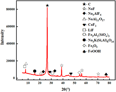
The experimental samples were collected from an aluminum electrolysis plant (Guizhou Province, China). The collected spent cathode carbon was crushed with a jaw crusher, further finely ground using a vibrating mill, so that all of it passed through a standard sieve of 150 mesh (106 μm), dried and bagged for use.The samples after grinding were analyzed by XRD and XRF, and the results were shown in Table 1 and Fig. 1, respectively.
| Element | C | F | Na | Al2O3 | SiO2 | S | CaO | Fe | Others |
|---|---|---|---|---|---|---|---|---|---|
| Content/% | 71.9 | 6.82 | 6.14 | 5.66 | 2.79 | 0.67 | 0.81 | 0.97 | 4.24 |
As can be seen from Table 1, the main constituent elements of SCC are F, Na, C, Si, Ca, S, Fe, and Al, among which C, F, Na and Al are the most abundant. As can be seen from Fig. 1, graphite is the main constituent material, accounting for about 71.9% of the total mass of raw materials, and the inorganic impurities are mainly NaF (9.59%), NaAl11O17 (5.98%), Na3AlF6 (1.21%), CaF2 (1.18%), and LiF (1.05%).
2.2 Experimental methods and procedures
Put 10 g ground spent cathode carbon block into a PTFE beaker, add a certain amount of water to the beaker, and put the PTFE beaker into an ultrasonic instrument for ultrasonic washing. The main purpose of washing is to remove sodium fluoride. The effects of time, liquid–solid ratio and ultrasonic power on the removal of sodium fluoride were investigated respectively. The spent cathode carbon after washing was filtered, dried and weighed as the raw material for the subsequent alkali leaching part. The remaining washing liquid was evaporated and crystallized to recover sodium fluoride.The 10 g washed sample was put into a PTFE beaker, and a certain amount of sodium hydroxide solution was added to the beaker. The PTFE beaker was put into an ultrasonic instrument, and the ultrasonic leaching was carried out after stirring evenly. The effects of alkali amount, time, temperature, liquid–solid ratio and ultrasonic power on the leaching of cryolite were investigated respectively. The spent cathode carbon after alkali leaching was filtered, dried and weighed as the raw material for the subsequent acid leaching part. The filtrate was sealed separately and stored as a raw material for subsequent synthesis of cryolite.
After the alkali leaching, 10 g of the sample after alkali leaching treatment was put into a PTFE beaker, and a certain concentration of hydrochloric acid solution was added to the beaker. The PTFE beaker was placed in an ultrasonic instrument, and ultrasonic leaching was started after stirring well. Since the optimum ultrasonic power and temperature were determined during the alkali leaching, and the effect in the acid leaching did not change much, the ultrasonic power and temperature are consistent with the alkali leaching process, and the effects of three main factors, namely, hydrochloric acid concentration, leaching time and liquid–solid ratio, on the leaching effect of calcium fluoride were investigated respectively. The spent cathode carbon after acid leaching was filtered, dried and weighed, and the filtrate was sealed separately and stored as a raw material for subsequent synthesis of cryolite.
The experiment was repeated three times under each experimental condition. Since there is no NaF with low solubility in the leaching process, all the substances that can be dissolved have entered the filtrate, so only a small amount of distilled water is needed to rinse the residual solution on the surface of the leaching residue, and the washing solution is poured into the leaching filtrate for preservation. The samples obtained after the filtration was dried and weighed for the fluorine element analysis test. The fluoride leaching rate is calculated by the following formula (1):
 | (1) |
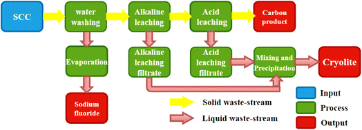
Finally, the acid-leaching filtrate was slowly poured into the alkali-leaching filtrate, and cryolite were precipitated at the appropriate pH, temperature, and time. The whole experimental process is shown in Fig. 2.
2.3 Equipment and characterization
This section lists the equipment and characterization methods required for the experiments.SCC samples were crushed using a jaw crusher (SP100×60, Guiyang Exploration Machinery Factory, China). A vibration mill prototype (XZM-100, Wuhan Exploration Machinery Factory, China) was used for grinding samples. The sample is filtered in the suction filter (SHB-111, Baoling Equipment, China). The composition of SCC was analyzed by X-ray diffraction (XRD) (Empyrean, PANalytical B.V., Netherlands) and X-ray fluorescence spectrometer (XRF) (AXIOSMAX Minerals, PANalytical B.V., Netherlands). SCC was washed and leached by ultrasonic equipment (KQ-600KDE, Kunshan Ultrasonic Instrument, China). The surface morphology of SCC before and after treatment was observed by SEM (Sigma300, Zeiss, Germany). The change of binding energy of surface elements before and after sample treatment was analyzed by X-ray photoelectron spectroscopy (XPS) (K-Alpha, Thermo Scientific, America). The effect of leaching process on the distribution of elements on the surface of SCC was observed by time-of-flight secondary ion mass spectrometry (TOF-SIMS) (PHI nanoTOFII, Physical Electronics, Germany).
3. Results and discussion
3.1 Water washing experiment
The solubility of NaF is very small, 4.3 g/100 ml at 25 °C, and it is extremely soluble in water, and the vast majority of NaF can be dissolved in water by water washing and it has little effect on other substances. Fig. 3 shows the experimental results under a series of water-washing conditions. Considering the influence of time, liquid–solid ratio, and ultrasonic power, the best washing conditions were obtained: time of 50 s, a liquid–solid ratio of 3![[thin space (1/6-em)]](https://www.rsc.org/images/entities/char_2009.gif) :
:![[thin space (1/6-em)]](https://www.rsc.org/images/entities/char_2009.gif) 1, and a washing power of 420 W. The filtrate of ultrasonic washing was poured into an evaporation dish for evaporation and crystallization, and the water in the solution was first evaporated at a high temperature. When the white solid was precipitated, the heating was stopped and the residual heat was used to evaporate it dry.
1, and a washing power of 420 W. The filtrate of ultrasonic washing was poured into an evaporation dish for evaporation and crystallization, and the water in the solution was first evaporated at a high temperature. When the white solid was precipitated, the heating was stopped and the residual heat was used to evaporate it dry.
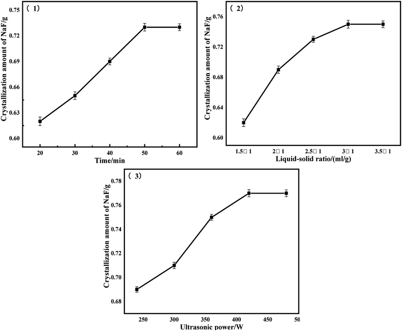 | ||
Fig. 3 Results of NaF recovered by water washing: (1) L![[thin space (1/6-em)]](https://www.rsc.org/images/entities/char_2009.gif) : :![[thin space (1/6-em)]](https://www.rsc.org/images/entities/char_2009.gif) S = 2.5 S = 2.5![[thin space (1/6-em)]](https://www.rsc.org/images/entities/char_2009.gif) : :![[thin space (1/6-em)]](https://www.rsc.org/images/entities/char_2009.gif) 1, P = 360 W; (2) t: 50 s; P = 360 W; (3) t: 50 s; L 1, P = 360 W; (2) t: 50 s; P = 360 W; (3) t: 50 s; L![[thin space (1/6-em)]](https://www.rsc.org/images/entities/char_2009.gif) : :![[thin space (1/6-em)]](https://www.rsc.org/images/entities/char_2009.gif) S = 3 S = 3![[thin space (1/6-em)]](https://www.rsc.org/images/entities/char_2009.gif) : :![[thin space (1/6-em)]](https://www.rsc.org/images/entities/char_2009.gif) 1. 1. | ||
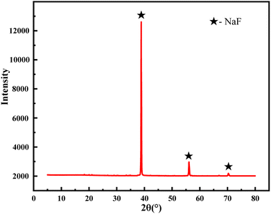
From Fig. 3, it can be seen that under the optimal washing conditions, 10 g of the sample can be washed to recover the white solid to the maximum extent of 0.77 g. The recovered white solids were tested by XRD, as shown in Fig. 4, the characteristic peak of the white solid was mainly sodium fluoride, and the recovered fluoride content reached 94.67%.
3.2 Alkali leaching experiment
The main purpose of alkaline leaching is to leach Na3AlF6 in the environment of sodium hydroxide alkaline solution, and some inorganic substances also participate in the reaction. According to the XRD results, the theoretical leaching rate of NaF and Na3AlF6 in the process of water washing and alkali leaching is 75.19%, which is compared with the actual leaching rate. The main chemical reaction occurring in the alkali leaching process is the formula (2):| Na3AlF6 + 4NaOH → NaAl(OH)4 + 6NaF | (2) |
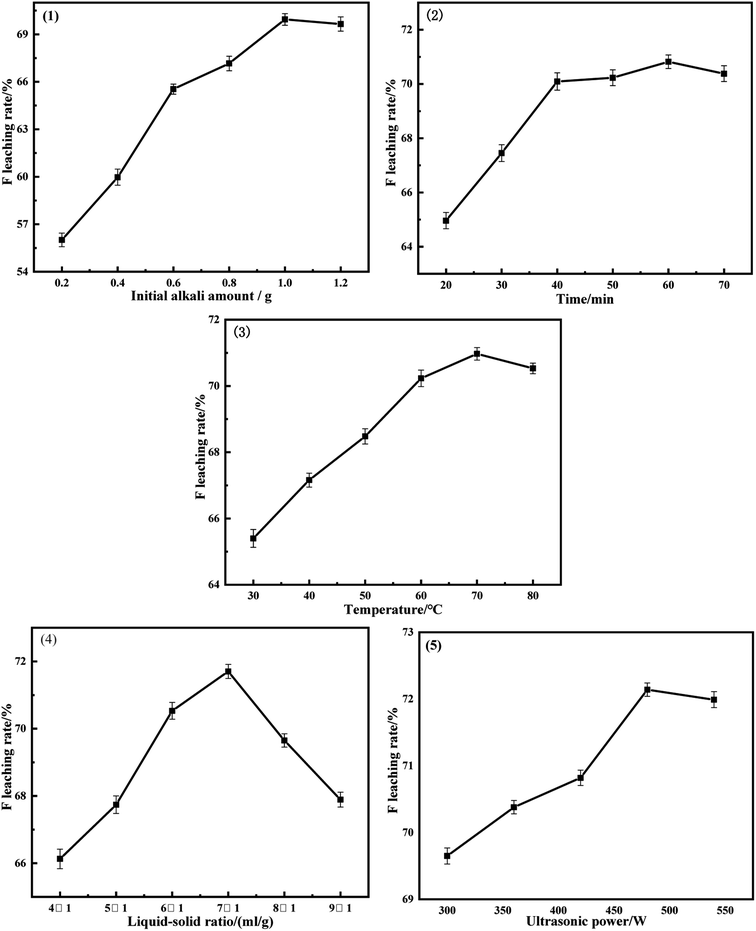
The one factor-at-a-time (OFAT) method was used to improve the leaching rate of fluoride, and Fig. 5 shows the experimental results under a series of leaching conditions. The trend of leaching effect under different experimental conditions eventually tends to be gentle, but under the experimental conditions of liquid–solid ratio, the leaching rate increases first and then decreases, and the trend gap is large. This is because after the optimal alkali amount is determined, the reaction concentration can be determined according to the value of liquid–solid ratio. If the liquid–solid ratio is too small or too large, the inorganic matter cannot be fully dissolved. A reasonable liquid–solid ratio should allow all reactants to have sufficient reaction space. It can be seen from Fig. 5 that when the liquid–solid ratio is 4![[thin space (1/6-em)]](https://www.rsc.org/images/entities/char_2009.gif) :
:![[thin space (1/6-em)]](https://www.rsc.org/images/entities/char_2009.gif) 1, the leaching rate is the lowest. At this time, the amount of water is too small, and inorganic substances cannot enter the solution for reaction. When the liquid–solid ratio was between 5
1, the leaching rate is the lowest. At this time, the amount of water is too small, and inorganic substances cannot enter the solution for reaction. When the liquid–solid ratio was between 5![[thin space (1/6-em)]](https://www.rsc.org/images/entities/char_2009.gif) :
:![[thin space (1/6-em)]](https://www.rsc.org/images/entities/char_2009.gif) 1 and 6
1 and 6![[thin space (1/6-em)]](https://www.rsc.org/images/entities/char_2009.gif) :
:![[thin space (1/6-em)]](https://www.rsc.org/images/entities/char_2009.gif) 1, the reaction began to proceed forward, and the leaching rate of F increased rapidly until the liquid–solid ratio was 7
1, the reaction began to proceed forward, and the leaching rate of F increased rapidly until the liquid–solid ratio was 7![[thin space (1/6-em)]](https://www.rsc.org/images/entities/char_2009.gif) :
:![[thin space (1/6-em)]](https://www.rsc.org/images/entities/char_2009.gif) 1. When the liquid–solid ratio continues to increase, the leaching rate of F decreases, and the concentration decreases with the increase of liquid–solid ratio, which affects the reaction. Considering the effects of alkali amount, time, temperature, liquid–solid ratio, and ultrasonic power, the best leaching conditions were obtained: alkali amount of 1 g, time of 60 min, the liquid–solid ratio of 7
1. When the liquid–solid ratio continues to increase, the leaching rate of F decreases, and the concentration decreases with the increase of liquid–solid ratio, which affects the reaction. Considering the effects of alkali amount, time, temperature, liquid–solid ratio, and ultrasonic power, the best leaching conditions were obtained: alkali amount of 1 g, time of 60 min, the liquid–solid ratio of 7![[thin space (1/6-em)]](https://www.rsc.org/images/entities/char_2009.gif) :
:![[thin space (1/6-em)]](https://www.rsc.org/images/entities/char_2009.gif) 1, temperature of 70 °C and ultrasonic power of 480 W. Under these conditions, the leaching rate of fluoride reached 72.14%.
1, temperature of 70 °C and ultrasonic power of 480 W. Under these conditions, the leaching rate of fluoride reached 72.14%.
3.3 Acid leaching experiment
The purpose of acid leaching is to leach the remaining fluoride into the solution as much as possible, and the reactions occurring during the acid leaching process are formulas (3) and (4). According to the XRD results, the fluorine leaching rate (72.14%) in the alkali leaching process did not reach the leaching rate (75.19%) when sodium fluoride and cryolite were completely removed, it was speculated that there was still a small amount of Na3AlF6 not completely dissolved due to the insufficient particle size of the sample. Continue to grind the spent cathode carbon after alkali leaching to 325 mesh (45 μm) for the acid leaching test, so there was still a possibility of a reaction (5) during the acid leaching process.| CaF2 + 2HCl → CaCl2 + 2HF | (3) |
| NaAl11O17 + 34HCl → NaCl + 11AlCl3 + 17H2O | (4) |
| Na3AlF6 + 6HCl → 3NaCl + AlCl3 + 6HF | (5) |
Fig. 6 shows the acid leaching test results under the main leaching conditions. The inorganic substance that reacts with hydrochloric acid during acid leaching is CaF2, and a part is used to neutralize a very small part of the alkali remaining in the solid after alkali leaching. Under the condition of single factor experiment, the leaching trend of each experiment tends to be stable. It can be seen from the Fig. 6 that the leaching rate reaches the maximum when the acid concentration is 0.6 mol L−1. When the acid concentration continues to increase, the leaching effect decreases instead. This is because the concentration increases, the proportion of water in the solution decreases, and the evaporation will be rapid under the action of high temperature and ultrasonic wave. As a result, the solution becomes thicker and the inorganic matter cannot be fully dissolved. Since the temperature and ultrasonic power were consistent with the alkali leaching process, the effects of hydrochloric acid concentration, time and liquid–solid ratio were comprehensively considered, and the optimum leaching conditions were obtained: hydrochloric acid concentration of 0.6 mol L−1, time of 60 min, the liquid–solid ratio of 5![[thin space (1/6-em)]](https://www.rsc.org/images/entities/char_2009.gif) :
:![[thin space (1/6-em)]](https://www.rsc.org/images/entities/char_2009.gif) 1, temperature of 70 °C, ultrasonic power 480 W. Under these conditions, the leaching rate of fluoride reached 82.99%.
1, temperature of 70 °C, ultrasonic power 480 W. Under these conditions, the leaching rate of fluoride reached 82.99%.
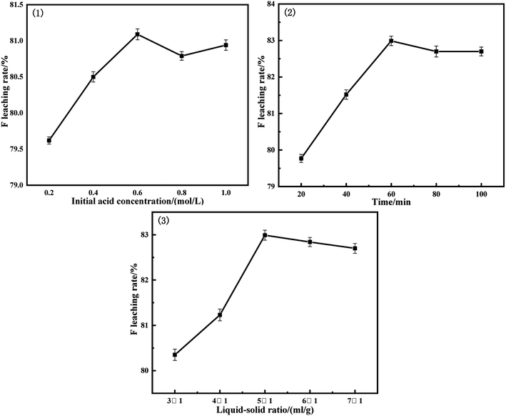 | ||
Fig. 6 Results of acid leaching rate of F: (1) t: 40 min, L![[thin space (1/6-em)]](https://www.rsc.org/images/entities/char_2009.gif) : :![[thin space (1/6-em)]](https://www.rsc.org/images/entities/char_2009.gif) S = 5 S = 5![[thin space (1/6-em)]](https://www.rsc.org/images/entities/char_2009.gif) : :![[thin space (1/6-em)]](https://www.rsc.org/images/entities/char_2009.gif) 1, T: 70 °C, P = 480 W; (2) CHCL: 0.6 mol L−1, L 1, T: 70 °C, P = 480 W; (2) CHCL: 0.6 mol L−1, L![[thin space (1/6-em)]](https://www.rsc.org/images/entities/char_2009.gif) : :![[thin space (1/6-em)]](https://www.rsc.org/images/entities/char_2009.gif) S = 5 S = 5![[thin space (1/6-em)]](https://www.rsc.org/images/entities/char_2009.gif) : :![[thin space (1/6-em)]](https://www.rsc.org/images/entities/char_2009.gif) 1, T: 70 °C, P = 480 W; (3) CHCL: 0.6 mol L−1, t: 60 min, T: 70 °C, P = 480 W. 1, T: 70 °C, P = 480 W; (3) CHCL: 0.6 mol L−1, t: 60 min, T: 70 °C, P = 480 W. | ||
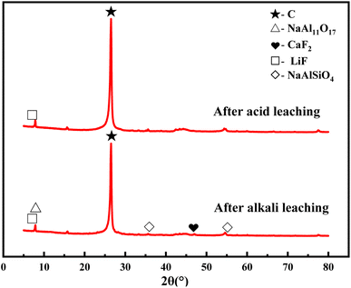
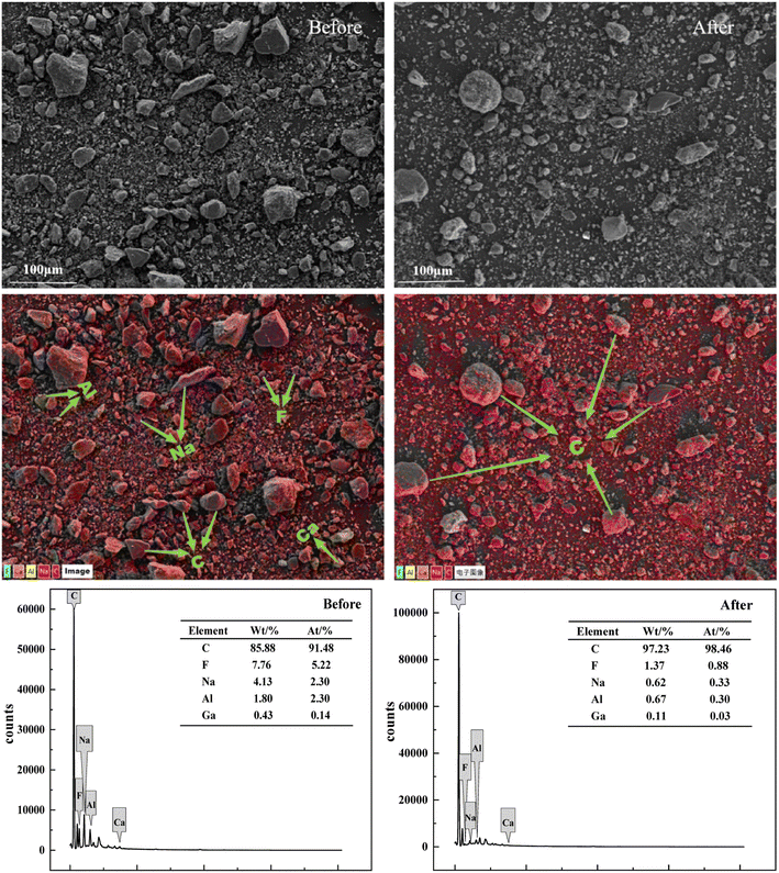
The SCC after alkali leaching and acid leaching was tested by XRD. It can be seen from Fig. 7 that the content of the sample after acid leaching was only carbon and lithium fluoride, and the remaining impurities were almost removed. SEM and EDS characterization was performed on the raw SCC and the SCC after the combined washing-leaching treatment to observe the external morphology. As can be seen from Fig. 8, after treatment, the large particle carbon become less, the surface has become smooth, the content of F, Na, Al and other elements decreases, and the content of carbon elements increases, indicating that the electrolyte in the spent cathode carbon has been basically dissolved in the solution.
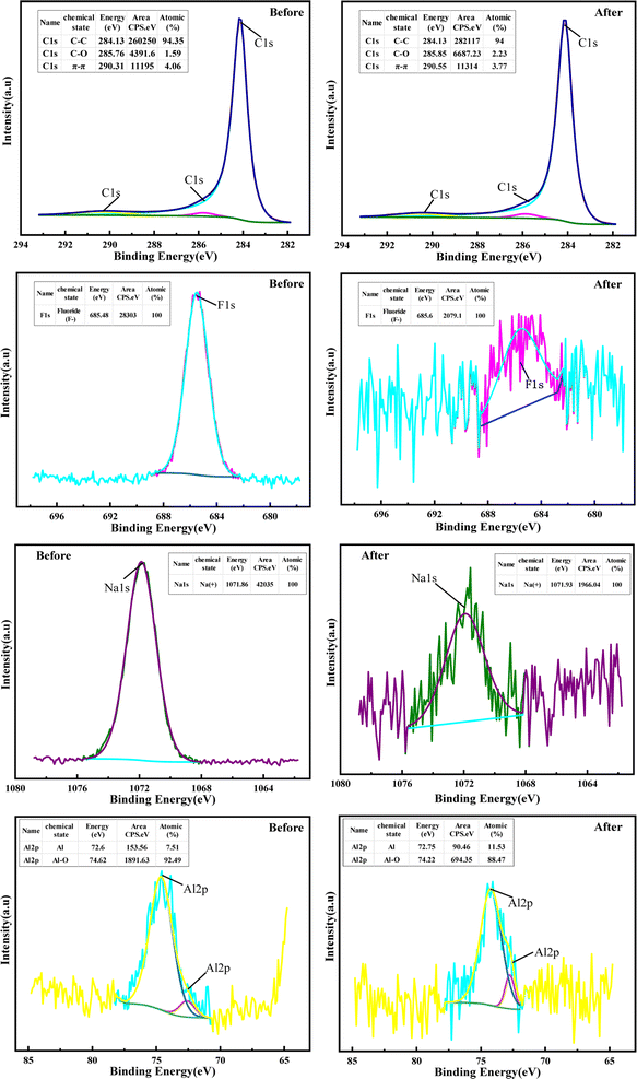
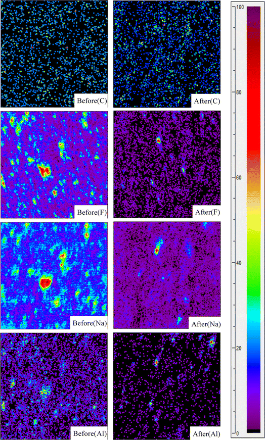
XPS and TOF-SIMS were used to characterize the raw SCC and the SCC after the combined washing-leaching treatment to explore the valence state and distribution of elements on the surface of SCC. It can be seen from Fig. 9 and 10 that the distribution of carbon elements becomes dense and the content increases after treatment. The elements such as fluorine, sodium, and aluminum became dispersed and the content decreased sharply. The valence state of the surface elements of SCC did not change after treatment, but the binding energy changed slightly, indicating that the chemical environment of SCC surface changed. It can be seen from the figure that a small amount of bulk SCC with high content has not been effectively treated, presumably due to the lack of fine particle size of the sample.
3.4 Harmless treatment of acid–base leaching solution
In the aforementioned experiments, only the leaching treatment was done for the spent cathode. The leaching filtrate was not treated, which contains a large number of fluorine ions and has certain recovery value. The cryolite regeneration method and chemical method were used to maximize the recovery of useful components in the leaching filtrate and to achieve the experimental process without wastewater pollution and discharge.| Al(OH)4− + 4H+ + 3Na+ + 6F− → Na3AlF6↓ + 4H2O | (6) |
Since the Na3AlF6 generated by the reaction (6) is flocculent, the filtration speed is slow, and the solution has reached normal temperature during the filtration process, so the reaction temperature can be taken as normal temperature. At normal temperature, the acid leaching filtrate was poured into the alkali leaching filtrate for 1 h to investigate the effect of pH on the amount of cryolite precipitation.
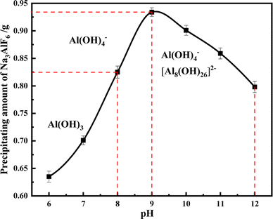
Since cryolite will form different forms of sodium aluminate solutions under high or low pH conditions, the existence form of Al ions in water is detected under different pH conditions, and the optimal precipitation conditions are determined. The results are shown in Fig. 11. When the pH is 6–8, there is a precipitate in the solution, which is mainly Al(OH)3; when pH > 8, the solution gradually generates Al(OH)4− and [Al8(OH)26]2−, which makes the formula (6) go forward. The precipitate is cryolite, and the maximum amount is generated at pH = 9, so the most suitable pH for the precipitation of Na3AlF6 is 9.
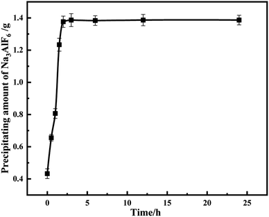
Since the precipitated cryolite is flocculated, it needs a certain reaction time to gather in a mass, and insufficient time results in very little precipitation. To determine the reaction time, the effect of different reaction times on the amount of precipitation was investigated at pH = 9 and normal temperature. As can be seen from Fig. 12, before 2 h, the amount of precipitation increases with time and the reaction power is sufficient, after reaching 2 h, the reaction tends to be gentle and the amount of precipitation is unchanged, so the best precipitation time is 2 h.
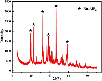
In summary, the optimal conditions for the generation of cryolite were pH = 9, precipitation time of 2 h, and normal temperature. The product was filtered and dried for XRD analysis. As shown in Fig. 13, the recovered fluoride has less impurities and the content reached 95%.
| Element | F | Na | Al | Ga |
|---|---|---|---|---|
| Before/(mg L−1) | 305 | 1227 | 67.4 | 4.84 |
| After/(mg L−1) | 9.06 | 56.7 | 18 | 2.33 |
4. Conclusions
In this experiment, the fluoride in the spent cathode carbon was dissolved to the maximum extent by using the combined washing-leaching method under ultrasonic-assisted conditions, and the harmless treatment of the washing solution and leaching solution and the useful substances were recovered. The following conclusions were obtained:(1) The optimal conditions for the water washing process were time of 50 s, liquid–solid ratio of 3![[thin space (1/6-em)]](https://www.rsc.org/images/entities/char_2009.gif) :
:![[thin space (1/6-em)]](https://www.rsc.org/images/entities/char_2009.gif) 1, and water washing power of 420 W. The most amount of sodium fluoride was recovered under these conditions, and the recovered fluoride content reached 94.67%.
1, and water washing power of 420 W. The most amount of sodium fluoride was recovered under these conditions, and the recovered fluoride content reached 94.67%.
(2) Under the combined process of washing and leaching, the leaching rate of fluoride reached 82.99%. The optimal conditions for precipitation of cryolite were pH = 9, time of 2 h and normal temperature environment, the recovered fluoride content reached 95%.
(3) The fluoride in the spent cathode carbon is recycled, and no solid waste and hazardous wastewater are discharged throughout the experiment, so as to realize resource utilization.
Conflicts of interest
There is no conflict that needs to be declared.Acknowledgements
We thank the National key R&D Program of China (No.2018YFC1903500) for financial support for this research.References
- T. Kati, S. Cristian and K. R. Jorn, Chemical Degradation of Cathode Linings in Hall-Héroult Cells — An Autopsy Study of Three Spent Pot Linings, Metall. Mater. Trans. B, 2011, 290–300, DOI:10.1007/s11663-011-9604-4.
- Z. Zhu, L. Xu and Z. Han, Defluorination study of spent carbon cathode by microwave high-temperature roasting, J. Environ. Manage., 2022, 302, 114028, DOI:10.1016/j.jenvman.2021.114028.
- I. V. Flores, F. Fraiz and R. A. Lopes Junior, Evaluation of spent pot lining (SPL) as an alternative carbonaceous material in ironmaking processes, J. Mater. Res. Technol., 2019, 8, 33–40, DOI:10.1016/j.jmrt.2017.11.004.
- G. Lei and M. Sina, Using SPL (Spent Pot-Lining) as an Alternative Fuel in Metallurgical Furnaces, Metall. Mater. Trans. E, 2016, 3, 179–188, DOI:10.1007/s40553-016-0085-x.
- H. Yuyao, W. Yaowu and Y. Jinzhong, Study on the Cathodic Behavior of Impurities in the Process of Aluminum Extraction by Soluble Anode Electrolysis, J. Electrochem. Soc., 2022, 169, 6, DOI:10.1149/1945-7111/ac74e3.
- Z. Yao, Q. Zhong and J. Xiao, An environmental-friendly process for dissociating toxic substances and recovering valuable components from spent carbon cathode, J. Hazard. Mater., 2021, 404, 124120, DOI:10.1016/j.jhazmat.2020.124120.
- S. B. Sleap, B. D. Turner and S. W. Sloan, Kinetics of fluoride removal from spent pot liner leachate (SPLL) contaminated groundwater, J. Environ. Chem. Eng., 2015, 3, 2580–2587, DOI:10.1016/j.jece.2015.09.004.
- Y. Yong, H. Jianhang and L. Yongkui, A new method for simultaneous separation and solidification of arsenic from arsenic-bearing gypsum sludge using waste carbon cathodes, Sep. Purif. Technol., 2022, 291, 120656, DOI:10.1016/j.seppur.2022.120656.
- L. F. Andrade-Vieira, L. C. Davide and L. S. Gedraite, Genotoxicity of SPL (spent pot lining) as measured by Tradescantia bioassays, Ecotoxicol. Environ. Saf., 2011, 74, 2065–2069, DOI:10.1016/j.ecoenv.2011.07.008.
- L. F. Andrade, L. C. Davide and L. S. Gedraite, The effect of cyanide compounds, fluorides, aluminum, and inorganic oxides present in spent pot liner on germination and root tip cells of Lactuca sativa, Ecotoxicol. Environ. Saf., 2010, 73, 626–631, DOI:10.1016/j.ecoenv.2009.12.012.
- N. Li, G. Xie and Z. X. Wang, Recycle of Spent Potlining with Low Carbon Grade by Floatation, Adv. Mater. Res., 2014, 881–883, 1660–1664, DOI:10.4028/www.scientific.net/AMR.881-883.1660.
- Z. D. Liu and X. H. Yu, Study on the process of treating waste cathode of aluminum electrolysis by alkali leaching flotation, Light Met., 2012, 3, 30–33, DOI:10.13662/j.cnki.qjs.2012.03.016.
- D. F. Lisbona, C. Somerfield and K. M. Steel, Leaching of spent pot-lining with aluminium nitrate and nitric acid: effect of reaction conditions and thermodynamic modelling of solution speciation, Hydrometallurgy, 2013, 134–135, 132–143, DOI:10.1016/j.hydromet.2013.02.011.
- D. F. Lisbona, C. Somerfield and K. M. Steel, Treatment of Spent Pot-lining with Aluminum Anodizing Wastewaters: Selective Precipitation of Aluminum and Fluoride as an Aluminum Hydroxyfluoride Hydrate Product, Ind. Eng. Chem. Res., 2012, 51, 12712–12722, DOI:10.1021/ie3013506.
- H. F. Lu, Experiment on roasting reduction of red mud with high iron by spent pot lining at high temperature, Light Met., 2015, 44, 9–11, DOI:10.13662/j.cnki.qjs.2015.01.003.
- Y. Xiao, L. Li and M. Huang, Treating waste with waste: metals recovery from electroplating sludge using spent cathode carbon combustion dust and copper refining slag, Sci. Total Environ., 2022, 838, 156453, DOI:10.1016/j.scitotenv.2022.156453.
- Y. Courbariaux, J. Chaouki and C. Guy, Update on Spent Potliners Treatments: Kinetics of Cyanides Destruction at High Temperature, Ind. Eng. Chem. Res., 2004, 43, 5828–5837, DOI:10.1021/ie049775x.
- K. Yang, J. Li and W. Huang, A closed-circuit cycle process for recovery of carbon and valuable components from spent carbon cathode by hydrothermal acid-leaching method, J. Environ. Manage., 2022, 318, 115503, DOI:10.1016/j.jenvman.2022.115503.
- J. Wang, H. Liu and Y. Luo, Study on Harmless and Resources Recovery Treatment Technology of Waste Cathode Carbon Blocks from Electrolytic Aluminum, Procedia Environ. Sci., 2012, 16, 769–777, DOI:10.1016/j.proenv.2012.10.105.
- Z. Shi, W. Li and X. Hu, Recovery of carbon and cryolite from spent pot lining of aluminium reduction cells by chemical leaching, Trans. Nonferrous Met. Soc. China, 2012, 22, 222–227, DOI:10.1016/S1003-6326(11)61164-3.
- Z. Yao, Q. Zhong and J. Xiao, Efficient separation of fluoride and graphite carbon in spent cathode carbon from aluminum electrolysis by mechanical activation assisted alkali fusion treatment, Miner. Eng., 2021, 161, 106717, DOI:10.1016/j.mineng.2020.106717.
- J. Xiao, J. Yuan and Z. Tian, Comparison of ultrasound-assisted and traditional caustic leaching of spent cathode carbon (SCC) from aluminum electrolysis, Ultrason. Sonochem., 2018, 40, 21–29, DOI:10.1016/j.ultsonch.2017.06.024.
- J. Yuan, J. Xiao and F. Li, Co-treatment of spent cathode carbon in caustic and acid leaching process under ultrasonic assisted for preparation of SiC, Ultrason. Sonochem., 2018, 41, 608–618, DOI:10.1016/j.ultsonch.2017.10.027.
- L. Zhang, W. Guo and J. Peng, Comparison of ultrasonic-assisted and regular leaching of germanium from by-product of zinc metallurgy, Ultrason. Sonochem., 2016, 31, 143–149, DOI:10.1016/j.ultsonch.2015.12.006.
| This journal is © The Royal Society of Chemistry 2023 |

