 Open Access Article
Nanostructured TiAlCuN and TiAlCuCN coatings for spacecraft: effects of reactive magnetron deposition regimes and compositions
Fadei F. Komarova,
Stanislav V. Konstantinov*a,
Igor V. Chizhovb,
Valery A. Zaikovb,
Tatiana I. Zubar *c and
Alex V. Trukhanov
 cd
cd
aA. N. Sevchenko Institute of Applied Physical Problems of Belarusian State University, Minsk 220045, Republic of Belarus. E-mail: svkonstantinov@bsu.by
bBelarusian State University, Minsk 220045, Republic of Belarus
cScientific and Practical Materials Research Center, National Academy of Sciences of Belarus, Minsk 220072, Republic of Belarus. E-mail: fix.tatyana@gmail.com
dSmart Sensors Laboratory, NUST MISiS, Moscow, 119049, Russia
First published on 21st June 2023
Abstract
Spacecraft are exposed to a number of factors in the outer space: irradiation by electron flows, high-energy ions, solar electromagnetic radiation, plasma irradiation, and a stream of meteorite particles. All these factors initiate various physical and chemical processes in spacecraft materials, which can eventually lead to failure. To ensure reliable operation of spacecraft, it is necessary to use protective coatings and special radiation-resistant materials. TiAlCuN and TiAlCuCN coatings were formed by reactive magnetron sputtering on different substrates: single-crystal silicon and Titanium Grade 2 wafers. Nitrogen was used as a reactive gas to form nitride coatings and acetylene was used to form carbonitride coatings. The elemental composition was studied by energy-dispersive X-ray (EDX) spectroscopy. The structural-phase state of the coatings was examined by X-ray diffraction (XRD) and scanning electron microscopy (SEM). Mechanical properties, such as hardness and Young modulus, were investigated by nanoindentation using a CSM Instruments Nanohardness Tester NHT2. The influence of deposition parameters, such as Ti and Al contents, the degree of reactivity α, and carbonitride formation on the structure and their mechanical properties were considered. It was detected that Cu addition to the coatings has effects on crystallite and growth column size refinement in comparison with the TiAlN and TiAlCN analogues due to its segregation along crystalline boundaries, and thus, imparts better mechanical characteristics. The hardness of TiAlCuN and TiAlCuCN coatings varies in the range of H = 25–36 GPa and Young modulus – E = 176–268 GPa. The impact strength index and the H/E* ratio, as well as the plastic deformation resistance index H3/E*2, were calculated. Due to their high mechanical properties, the formed nitride and carbonitride coatings are promising for use in space technologies.
Introduction
The design and formation of nanostructured coatings with high hardness, wear resistance, and resistance to radiation is one of the most important areas of research in the field of materials science nowadays.1–5The continuously growing interest of scientists in studying the processes of formation and the properties of nanostructured coatings is associated with the discovery of new unique properties of such systems or with the enhancement of their already known useful characteristics. Titanium nitride coatings are widely used in industry. They were originally developed to increase the service life of tools and mechanism parts.6 However, the properties of such coatings were significantly improved by introducing additional elements into their composition.7–9 In particular, the addition of Al to TiN increases oxidation resistance, hardness, and wear resistance. The TiAlN and TiAlCN coatings have high hardness and wear resistance, corrosion resistance, and good thermal and chemical stability, and are promising materials for use in mechanical components of space technology.7–11
One of the most common methods for obtaining nanostructured nitride and carbonitride coatings is reactive magnetron sputtering (RMS). The RMS method makes it possible to form high-quality coatings with specified optical and mechanical properties. An important problem in the formation of coatings by ion-plasma methods is the prediction of their composition, structure, and, consequently, their physical and mechanical properties.12 In a number of published studies12–15 it has been shown that all the deposition parameters seriously influence the coating structure and mechanical characteristics.
Reliable operation of spacecraft components requires the use of wear-resistant coatings with antifriction properties. In particular, tribological elements of the gyroscope system, such as thrust bearings, need to be covered with hard antifriction coatings. The addition of carbon, copper, and silver to the composition of TiAlN coatings reduces the coefficient of friction and increases the service life of the mechanical assembly.7,16
The optical characteristics of the TiAlN and TiAlCN coatings also deserve attention. Varying the ratio of Ti/Al/C/N components in the deposited coating makes it possible to obtain a film with the necessary optical characteristics.17 TiAlN coatings provide passive thermoregulation for artificial Earth satellites and small spacecraft.18 A thermal control coating is a surface whose thermo-optical properties are designed to achieve a desirable surface temperature when exposed to a known solar flux or other radiation sources. The main optical parameters of thermal control coatings are optical absorption (also known as solar absorption) (αs) and thermal emissivity (εN). The equilibrium temperature of the spacecraft is dependent on a ratio αs/εN. An increase in the aluminum content in the composition of the TiAlN coating leads to an increase in the αs/εN ratio.17
To improve the mechanical characteristics of nitride and carbonitride coatings, composite materials with copper and silver additives are being developed, which further reduce the friction coefficient and increase the wear resistance of coating composites.16,19–25 The increase in wear resistance of nitride coatings with the addition of silver and copper is based on the insolubility of these metals in the metal nitride matrix. The nanoparticles of these soft metals act as solid lubricants when they come into instant contact with the friction pair element.16,19
In the literature,16,19–21 the addition of copper impurities to TiAlN coatings is noted to prevent the migration of grain boundaries. Therefore, it reduces both the crystal size and the grain size, participates in the nucleation of the main phase, and reduces the average hardness of the nanocomposite. All processes operate simultaneously during the entire deposition time. With the increase in the content of impurity metal phase Cu, the coating structure of nanocomposites also clearly transforms. At a certain optimal copper impurity concentration, nc-TiAlN/Cu nanocomposite coatings can reach ultrahigh hardness.16 Their structure consists of typical columnar grains with very fine metal crystals embedded in the boundaries.20 The nanocomposite coating, composed of smaller columnar grains, retains the original preferred orientation and exhibits increased hardness, which is usually accompanied by a higher residual compressive stress. This is because the higher compressive stress prevents the coating from plastically deforming in a columnar grain structure by inhibiting slip and rotation. The higher compressive stress arises due to the suppression of the strong tendency to increase the columnar diameter of the grains.20 At a relatively high level of metal impurity, the grain size is significantly reduced, and at the same time, a sufficient surface area is provided for repeating nuclei with random orientation.20–23 Moreover, the embryos survive competitive growth and grow in favorable directions. As a result, the nanocomposite coating's texture gradually weakens. The hardness decreases along with lower compressive stress due to the different grain growth rates, resulting in a weakened texture.20–23
In,24,25 the influence of copper and silver additives on the mechanical properties of CrN, TiN, and TaN coatings was studied. It is noted that an increase in the concentration of Cu and Ag from 1 to 8% leads to a decrease in the friction coefficient and an increase in wear resistance. It was shown in19 that the addition of 10% copper and 6% silver to the TiAlN coating composition leads to a decrease in hardness by a factor of 2, residual stresses by a factor of 10, friction coefficient by a factor of 2.5, and wear volume by a factor of 2.5. Transmission microscopy and electron diffraction have shown that the Cu and Ag particles are of crystalline nature. In this case, depending on the concentration of Cu and Ag, the sizes of nanocrystals vary in the range of 3–1000 nm.
TiAlN and TiAlCN coatings with the addition of Cu were chosen as the object of this research, which is very promising both for the deposition on AA2024 alloy and for the deposition on Titanium Grade 5 and Titanium Grade 2-type alloys. In the equilibrium case, the system is characterized by the presence of α-phase titanium, the temperature stability region of which should expand towards high temperatures due to the presence of an α-phase stabilizer – nitrogen. There is very little information in the literature concerning the TiAlCuN coating.19–21,26,27 Moreover, no information was detected about the carbonitride variation of this composition – TiAlCuCN coating. In this regard, the study of these fundamentally new coatings and the accumulation of experimental data on them is an urgent task.
The developed nanostructured coatings TiAlN and TiAlCN with Cu additives will be relevant primarily for the operation as protective radiation-resistant coatings on the bodies of small aircrafts in the Earth orbit and outer space. Spacecraft, in the course of their operation, are exposed to a number of effects of outer space: irradiation by electron flows, high-energy ions, solar electromagnetic radiation, plasma irradiation, as well as a stream of meteorite particles. All these factors initiate various physical and chemical processes in the spacecraft materials, which can eventually lead to failure. To ensure reliable operation of the spacecraft, it is necessary to use protective coatings and special radiation-resistant materials. In particular, to ensure the reliable functioning of friction units in spacecraft, excluding sticking, the nanostructured nitride and carbonitride coatings TiAlN and TiAlCN with Cu additives are utilized.
In this paper, the effect of reactive magnetron deposition regimes and target compositions on the elemental composition, structural-phase state, and mechanical properties of nanostructured TiAlCuN and TiAlCuCN coatings was investigated. The focus was directed to Cu addition and reactivity degree α impacts.
Experimental
Synthesis of nanostructured TiAlCuN and TiAlCuCN coatings
The TiAlCuN and TiAlCuCN thin coatings were obtained using the TiAlCu composite targets no. 3 (46 at% Ti, 46 at% Al, 8 at% Cu) and no. 4 (69 at% Ti, 23 at% Al, 8 at% Cu) by reactive magnetron sputtering. The targets were produced by the metal powder compression method by explosive pressing in order to obtain homogeneous elemental compositions. These coatings were deposited onto different substrates: silicon Si (100) and Titanium Grade 2. The amount of carbon in TiAlCuCN coatings was controlled by the ratio of partial pressures of reactive gases N2/C2H2. Table 1 shows the ratio of partial pressures of nitrogen and acetylene. The deposition processes were carried out at two values of the degree of reactivity α: α = 0.605 (the coatings of composition close to stoichiometric – regime 1) and α = 0.474 (the coatings of non-stoichiometric composition enriched with metallic Ti and Al components – regime 2).| α | 0.605 | 0.474 | ||||||
| Coating type | TiAlCuN | TiAlCuCN | TiAlCuN | TiAlCuCN | ||||
| Discharge current, I, А | 1.0 | 1.0 | 1.0 | 1.0 | ||||
| Voltage U, V | 370–400 | 390–440 | 370–400 | 390–440 | ||||
| Pressure P, Pa | 7.0 × 10⁻² | 7.0 × 10⁻² | 7.0 × 10⁻² | 7.0 × 10⁻² | ||||
| PN2/PC2H2 | — | 1/1 | — | 1/1 | ||||
| Ubias, V | −200 | −200 | −200 | −200 | ||||
| T, °C | 370 | 380 | 370 | 380 | ||||
| Target | 3 | 4 | 3 | 4 | 3 | 4 | 3 | 4 |
| Sample number | 3N1 | 4N1 | 3CN1 | 4CN1 | 3N2 | 4N2 | 3CN2 | 4CN2 |
The operating mode of the ion source was set by the following parameters: argon pressure PAr = 6.0 × 10⁻² Pa; ion source discharge current I = 25 mA; ion source discharge voltage U = 2.8 kV; cleaning time t = 15 min. Additionally, a negative bias was applied to the substrates (Ub =−200 V), which made it possible to obtain an ion displacement current on the substrates equal to Ib = 40 mA. The average ion current density j on the substrate was j = 0.63 mA cm−2 and the average energy of Ar ions on the substrate was E = 140 eV. The choice of discharge parameters and cleaning time is based on the preliminary tests carried out and is due to stable discharge burning and high cleaning speed.
The deposition of TiAlCuN and TiAlCuCN coatings by reactive magnetron sputtering was carried out at a modernized UVN-2M facility (Fig. 1) equipped with a magnetron sputterer, ≪Radikal≫ ion source, substrate heating system, bias supply to the substrate, and the modular gas flow control complex (MGFCC).28,29 The vacuum chamber equipped with a nitrogen trap was evacuated using a diffusion steam-oil pump and a fore-vacuum pump. The vacuum system made it possible to obtain the ultimate residual pressure of 9.0 × 10⁻⁴ Pa. The deposited substrates were mounted on a flat heated substrate holder. The sample sizes ranged from 10 mm to 25 mm and were located in the deposition zone with a diameter of ∼90 mm. The spread of the film thickness in the deposition zone did not exceed 10%. The substrates made of Titanium Grade 2 had a polished surface for sputtering and standard dimensions of 12 mm by 17 mm and 2.0 mm thickness.
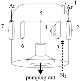 | ||
| Fig. 1 Vacuum chamber structure of the modernized UVN-2M facility. 1 – Optical sensor MGFCC; 2 – magnetron; 3 – substrate holder; 4 – IR heater; 5 – rotation system; 6 – damper; 7 – ion source. | ||
The pressure in the chamber was measured using a VIT3 vacuum gauge. A PMI-51 ionization lamp was used as a sensor. The argon flow rate was controlled by the MGFCC28,29 using feedback between the output signal of the vacuum gauge and the signal to the argon vibrating leak.
To control the consumption of reactive gas N2, the optical radiation spectrum from the discharge was used, which varied depending on the nitrogen content in the vacuum chamber. A single-channel algorithm was used for monitoring and controlling the consumption of reactive gas N2 (programmed in MGFCC process no. 3), which is reduced to recording and maintaining the intensity of one control spectral element at a given level. The titanium line Ti 506.5 nm was used as a control parameter, the intensity value of which is related to the degree of reactivity α. The degree of reactivity α is the main parameter that determines the composition and, thus, the structure and properties of the TiAlCuN and TiAlCuCN coatings that were deposited. The degree of reactivity α was determined from the discharge in the optical spectrum according to the following formula:28
 | (1) |
Thus, the modular gas flow control complex (MGFCC) used by us maintains a constant ratio of target metal atoms and reactive gas flows onto the substrate at constant operating pressure and parameters at the power source. This method of control and monitoring of reactive magnetron deposition makes it possible to maintain its nonequilibrium state in a stationary manner, ensuring the uniform distribution of elements over depth, and increase the reproducibility of coating formation in terms of composition and thickness.28,29
Coating characterization methods
The morphology and microstructure of the obtained TiAlCuN and TiAlCuCN coatings were studied by scanning electron microscopy (SEM) using a Hitachi S-4800 electron microscope (Japan) operating in the secondary electron mode as well as backscattered electron mode with 15 keV electrons. The electron microscope was equipped with an X-ray sensor (energy-dispersive spectrometer), which makes it possible to determine the elemental composition of coatings by the method of energy-dispersive X-ray spectroscopy (EDX). The error in measuring the atomic concentration of basic elements was no more than 0.5 at%. The coating thicknesses were studied using SEM micrographs of cleaved samples.Structural-phase analysis of TiAlCuN and TiAlCuCN coatings was carried out by the X-ray diffraction method using an X-ray powder diffractometer (ADANI POWDIX 600/300) operating in the Bragg–Brentano configuration with the radiation wavelength CoKα = 1.7889 Å.
The hardness of the obtained samples was measured by the nanoindentation method according to the Oliver and Pharr methodology30,31 using a NanoHardness Tester (NHT2; CSM Instruments, Switzerland) equipped with a Berkovich diamond tip. In measurements, Poisson's ratio of TiAlCuN and TiAlCuCN coatings was taken to be equal to ν = 0.3.10,32
Results and discussion
Elemental analysis of the coatings
Fig. 2 shows the energy-dispersive X-ray spectrum for the TiAlCuN nitride coating obtained using target 3. The presence of the following elements was detected in the formed coating: Ti, Al, Cu, Ar, N, and C. The oxygen concentration does not exceed the measurement error. Fig. 3 shows the energy-dispersive X-ray spectrum for the TiAlCuCN carbonitride coating (sample 3CN2). The presence of acetylene gas leads to a significant increase in the carbon line.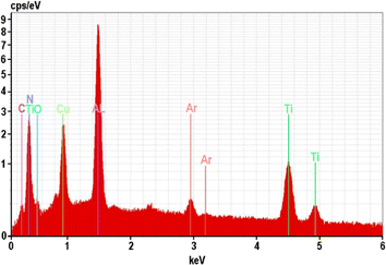 | ||
| Fig. 2 EDX spectrum of the TiAlCuN nitride film deposited on the silicon substrate (sample 3CN1; α = 0.605). | ||
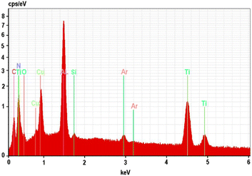 | ||
| Fig. 3 EDX spectrum of the TiAlCuCN carbonitride film deposited on the silicon substrate (sample 3CN2; α = 0.474). | ||
Table 2 shows the elemental composition of the TiAlCuN nitride coatings on silicon substrates formed in different regimes. The composition of TiAlCuN does not contain ineligible elements in any significant quantities. Table 3 presents the composition stoichiometry, thickness (h), deposition time (τ), and rate (v) of the TiAlCuN nitride coatings on Si substrates. The coating thickness varies in the range of 1120–1900 nm. Table 4 shows the elemental composition of TiAlCuCN carbonitride coatings on the silicon substrate formed in different regimes. The composition of TiAlCuCN does not contain any foreign elements in significant quantities. Table 5 shows the composition stoichiometry, thickness (h), deposition time (τ) and rate (v) of the TiAlCuCN carbonitride coatings on Si substrates. The coating thickness varies in the range of 1460–2120 nm. According to the obtained results, it can be considered that the elemental composition of the targets is transferred with high accuracy to the coatings in all the deposition regimes used.
| Sample | Component composition | ||||||
|---|---|---|---|---|---|---|---|
| Ti | Al | Cu | N | C | Si | Ar | |
| 3N1 | 17.10 | 27.70 | 8.07 | 43.42 | 2.47 | 0.20 | 1.04 |
| 3N2 | 18.52 | 29.53 | 9.95 | 37.20 | 1.77 | 1.35 | 1.68 |
| 4N1 | 30.55 | 14.64 | 8.59 | 41.85 | 3.68 | 0.20 | 0.49 |
| 4N2 | 43.27 | 13.52 | 10.32 | 28.10 | 3.60 | 0.37 | 0.82 |
| Sample | (Ti + Al), at% | (N + C), at% | (Ti + Al)/(N + C) | h, nm | τ, s | v, nm s−1 |
|---|---|---|---|---|---|---|
| 3N1 | 44.80 | 45.89 | 0.976 | 1900 | 5400 | 0.352 |
| 3N2 | 48.05 | 38.97 | 1.233 | 1290 | 2580 | 0.500 |
| 4N1 | 45.19 | 45.53 | 0.993 | 1120 | 3000 | 0.373 |
| 4N2 | 56.79 | 31.70 | 1.791 | 1280 | 2580 | 0.496 |
| Sample | Component composition | ||||||
|---|---|---|---|---|---|---|---|
| Ti | Al | Cu | N | C | Si | Ar | |
| 3CN1 | 18.02 | 24.21 | 7.01 | 27.55 | 20.81 | 1.09 | 1.31 |
| 3CN2 | 23.76 | 28.01 | 7.32 | 24.43 | 15.56 | 0.28 | 0.64 |
| 4CN1 | 35.76 | 15.75 | 6.15 | 23.59 | 18.14 | 0.20 | 0.41 |
| 4CN2 | 44.42 | 15.55 | 7.54 | 22.22 | 8.77 | 0.36 | 1.14 |
| Sample | (Ti + Al), at% | (N + C), at% | (Ti + Al)/(N + C) | h, nm | τ, s | v, nm s−1 |
|---|---|---|---|---|---|---|
| 3CN1 | 42.23 | 48.36 | 0.873 | 1460 | 3000 | 0.487 |
| 3CN2 | 51.77 | 39.99 | 1.295 | 1530 | 2580 | 0.593 |
| 4CN1 | 51.51 | 41.73 | 1.234 | 1580 | 3000 | 0.527 |
| 4CN2 | 59.97 | 30.99 | 1.935 | 1640 | 2580 | 0.636 |
X-ray diffraction analysis
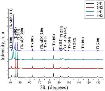
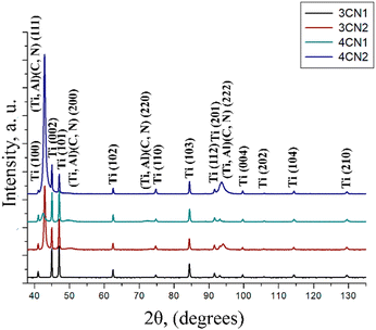
As shown in the obtained diffraction patterns from TiAlCuN and TiAlCuCN coatings (Fig. 4 and 5), the diffraction peaks from the titanium substrate Ti (100), (002), (101), (102), (110), (103), (112), (201), (004), (202), (104), and (210) were found, indicating a hexagonal close-packed (hcp) lattice.It was detected that both TiAlCuN and TiAlCuCN coatings have a uniform single-phase structure presented by (Ti, Al)N and (Ti, Al)(C, N) disordered solid solutions with a face-centered cubic (fcc) lattice. The highly diffused nature of the (Ti, Al)N and (Ti, Al)(C, N) peaks witnesses to the nanocrystalline structure of the TiAlCuN as well as TiAlCuCN coatings. These diffraction peaks are shifted from pure titanium nitride to the region of larger 2θ angles. The diffraction peaks (Ti, Al)N (200) are shifted from 40.76° 2θ for the pure titanium nitride to 41.09° 2θ. This fact indicates the replacement of titanium atoms by aluminum atoms with a smaller atomic radius: RTi = 1.47 Å, RAl = 1.43 Å.33 The formation of a single-phase structure is usually observed for TiAlN10,11,29 and TiAlCN7,9,17 coatings. It follows from this fact that the addition of copper does not change the phase composition of the coating and does not lead to the formation of new phases.
The absence of any carbide phase in the case of TiAlCuCN coatings indicates that carbon is in the titanium nitride solid solution and replaces nitrogen atoms with smaller atomic radii (RC = 0.77 Å, RN = 0.70 Å).31 This effect leads to an additional shift in the (Ti, Al)(C, N) (111), (200), (220), and (222) diffraction peaks towards larger 2θ values. The diffraction peaks (Ti, Al)(C, N) (200) are shifted from 41.09° 2θ for (Ti, Al)N to 40.89° 2θ, which is still more than 40.76° 2θ for the pure titanium nitride. No individual diffraction peaks from copper or copper-contained phases were found. At the same time, no significant shift in the diffraction peak positions in comparison with previous results for the (Ti, Al)N phase10,11,29 was revealed, assuming the dissolution of copper in the nitride (Ti, Al)N. In this regard, it is possible to draw the conclusion that copper segregates along the crystallite boundaries in the amorphous state and thus prevents their growth in the TiAlCuN and TiAlCuCN coatings. The possibility of this was described in earlier works.26,27 The calculated lattice parameters were a = 4.207 Å and a = 4.2268 Å for TiAlCuN and TiAlCuCN coatings, respectively. In both cases, it is less than a = 4.241 Å for pure titanium nitride and about the same value as for TiAlN coatings. From the results of the structure analysis conducted, it follows that the stresses presented in the TiAlCuN and TiAlCuCN coatings approximately correspond to the values for TiAlN coatings. The estimated average sizes of (Ti, Al)N crystallites are about 30–40 ± 5 nm in the case of TiAlCuN coatings and 20–30 ± 5 nm for (Ti, Al)(C, N) crystallites in the case of TiAlCuCN ones.
From the results of TiAlCuN and TiAlCuCN coatings' X-ray diffraction analysis, it follows that all deposition regimes used lead to the formation of single-phase structures presented by the (Ti, Al)N and (Ti, Al)(C, N) disordered solid solutions with a face-centered cubic (fcc) lattice.
Microstructural analysis of thin films
For structure and morphology investigations by SEM, the TiAlCuN and TiAlCuCN coatings were deposited onto monocrystalline silicon (100) substrates in order to acquire not only plan-view images but also cross-sectional ones.The TiAlCuN coating surfaces and cross-sectional images obtained by SEM are shown in Fig. 6. A characteristic dense columnar microstructure is observed, with columns increasing slightly in diameter with the growth of coatings. It was observed that the average column size does not exceed 80 nm.
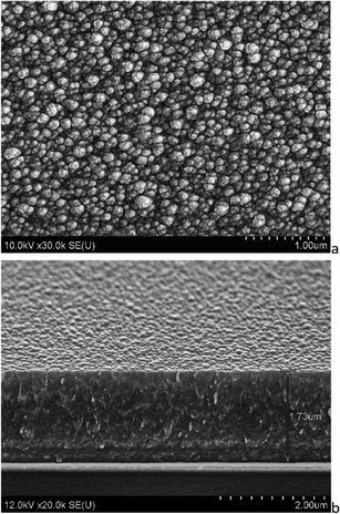 | ||
| Fig. 6 SEM micrographs of the TiAlCuN nitride film deposited on the silicon surface (a) and the cleavage sample (b). Sample 3N1; substrate − Si; α = 0.605. | ||
Fig. 7 shows the TiAlCuCN coating (3C2 sample) surface and cross-sectional microstructure obtained by SEM. This coating was formed in the regime with an excess concentration of Ti and Al metal components over the reactive components (N, C) and a reactivity degree α = 0.474. A dense columnar microstructure is characteristic, with a slight increase in the columns' diameter as coating growth occurs. The average column size does not exceed 50–60 nm.
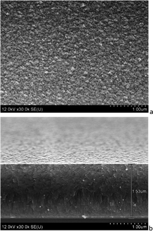 | ||
| Fig. 7 SEM micrographs of the TiAlCuCN carbonitride film deposited on the silicon surface (a) and the cleavage sample (b). Sample 3CN2; substrate − Si; α = 0.474. | ||
The SEM average crystallite size results correlate well with the data based on XRD analysis. The TiAlCuN and TiAlCuCN coating cross-sections show that the surface of all coatings is smooth and uniform. There are no cracks and voids in the structure, which can have a negative impact on the mechanical properties of the coatings. A clear film–substrate interface can be observed on all the obtained SEM cross-sectional images. The cross-sectional images of TiAlCuN and TiAlCuCN coatings allow us to conclude that the films adhere well to the substrate. The resulting coatings are homogeneous, dense, and do not contain visible defects over the entire surface area.
In comparison with TiAlN10,11,29 and TiAlCN7,9,17 coatings, TiAlCuN and TiAlCuCN coatings demonstrate a more dispersive nanostructure with a lower average crystalline size and a lower average size of growth columns. This effect occurs due to the segregation of copper along crystalline boundaries, as revealed by XRD (Fig. 4 and 5).
Mechanical properties of TiAlCuN and TiAlCuCN coatings
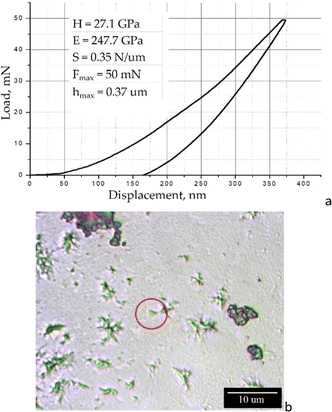
The coatings' mechanical properties were investigated by nanoindentation according to the Oliver and Pharr methodology.30,31 CSM Instruments NanoHardness Tester (NHT2) (Switzerland) with a Berkovich diamond tip was used. The measurements and the formation of load–unload curves were carried out at a maximum load on the indenter of 0.05–0.1 N. Fig. 8 shows the load–unload curve, as well as the indenter imprint photograph on the TiAlCuN coating surface. From the load–unload curve analysis, where no steps or breaks are found, it follows that all the formed TiAlCuN and TiAlCuCN coatings are dense and uniform in thickness.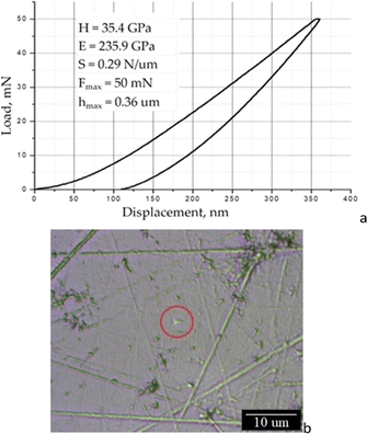 | ||
| Fig. 8 Load–unload curve (a) and micrographs of indenter print (b) from the TiAlCuN coating. Sample 3N1; substrate – Titanium Grade 2; α = 0.605. | ||
Fig. 9 shows the load–unload curve as well as the indenter imprint microphotograph on the TiAlCuCN coating surface. In all cases, the indenter imprints on the surface are regular equilateral triangles, repeating the shape of the Berkovich indenter used for these measurements. At the same time, there are no cracks, deformations, or other defects from the indentation, which indicates a viscous mechanism of coating destruction under the load. This fact witnesses to the high impact strength of deposited coatings. The latter parameter is especially important for those coatings operating in the outer space, where the temperature is about 4 K. At such temperatures, which are significantly below the cold-brittleness threshold for many materials, the formed nitride and carbonitride coatings TiAlCuN and TiAlCuCN can help to prevent embrittlement of structures made of aircraft-grade titanium (Titanium Grade 2, Titanium Grade 5), aluminum (AA2024), as well as steel (AISI 304) alloys. Table 6 represents the mechanical characteristics of the examined coatings.
 | ||
| Fig. 9 Load–unload curve (a) and micrographs of indenter print (b) from the TiAlCuCN coating. Sample 3CN2; substrate – Titanium Grade 2; α = 0.474. | ||
| Sample | H, GPa | E, GPa | E*, GPa | H/E* | H3/E*2 |
|---|---|---|---|---|---|
| 3N1 | 35.4 | 235.90 | 259.23 | 0.14 | 0.66 |
| 3N2 | 31.3 | 267.60 | 294.07 | 0.11 | 0.35 |
| 3CN1 | 29.0 | 176.30 | 193.74 | 0.15 | 0.65 |
| 3CN2 | 27.1 | 247.70 | 272.20 | 0.10 | 0.27 |
| 4N1 | 31.0 | 265.10 | 291.32 | 0.11 | 0.35 |
| 4N2 | 29.3 | 256.40 | 281.76 | 0.10 | 0.32 |
| 4CN1 | 28.9 | 240.90 | 264.73 | 0.11 | 0.34 |
| 4CN2 | 25.4 | 249.80 | 274.51 | 0.09 | 0.22 |
According to the results, the coating hardness varies in the range of H = 25–36 GPa and Young's modulus – E = 176–268 GPa. The highest hardness detected − H = 35.4 GPa and Young's modulus of E = 235.9 GPa were recorded for the TiAlCuN coating formed in regime 1 with a stoichiometric concentration of nitrogen from target 3 on a grade 2 titanium substrate, as shown in Fig. 8. It was discovered that regime 2 with reactive gas deficiency lowers the coating hardness by 5–12% but can enhance Young's modulus of the coatings by 13–24% in both cases of nitride and carbonitride coatings. In general, it was found that nitride coatings are 6–17% harder than their carbonitride counterparts. Analogous dependencies on reactive gas concentration and the presence of carbon were detected in our previous research studies for TiAlN10,11,29 and in the literature for TiAlCN8,9,17 coatings. This means that the addition of copper to the composition of coatings for mechanical properties leads, first of all, to an increase in their hardness.
The situation is more complicated with Ti and Al contents influencing the mechanical properties. In previous research studies, there is a growing body of evidence, on one hand, that the increased Ti content leads to increased TiAlN coating hardness.1 On the other hand, there are proofs that Ti and Al contents, close to equimolar, are optimal for hardness enhancement.34 The conducted TiAlCuN and TiAlCuCN coating investigations prove the correctness of the latter, since samples obtained from target 3 with 46 at% Ti content and 46 at% Al content demonstrate 4–13% higher hardness in comparison with the ones obtained from target 4 with 69 at% Ti content and 23 at% Al content, as shown in Table 6.
As it was reviewed by Matthews and Leyland,35 and Musil,36 the wear behaviour is usually determined by the ratio H/E*, where H is the hardness and E* is the effective Young's modulus. The latter is given by E* = E/(1 − ν2), where E is Young's modulus and ν is Poisson's ratio. In this respect, a high H/E* ratio is desirable, as it characterizes the value of elastic recovery during unloading for nano- and microcontact interaction. The hard coatings satisfying the ratio H/E* > 0.1 exhibit enhanced resistance to plastic deformation and distribute the load applied to the coating over a wider area, which results in an increase in the resistance of the coating to cracking.34,36,37 Such coatings are simultaneously hard and tough.34
The indices of plastic deformation, as expressed by H3/E*2,38 were also estimated for the studied coatings. The calculated values H/E* and H3/E*2 for nitride and carbonitride TiAlCuN and TiAlCuCN coatings are presented in Table 6.
The H/E* value for the formed coatings is in the range of 0.1–0.15, which indicates the ability of TiAlCuN and TiAlCuCN coatings to resist plastic deformation and, at the same time, to have high durability. The H3/E*2 value is in the range of 0.22–0.66, which also indicates the resistance of nitride and carbonitride coatings to plastic deformation. These values are up to 25% higher than those obtained on the TiAlN coatings.34 Such combinations indicate the coatings' ability to distribute the load applied to the surface over a wider area, which results in an increase in the resistance to cracking and embrittlement. The obtained values of hardness H, Young's modulus E, H/E* and H3/E*2 ratios allow us to state that the formed nitride and carbonitride coatings have good mechanical properties and will be useful in mechanical engineering, in particular in the space industry.
Conclusions
Nitride and carbonitride TiAlCuN and TiAlCuCN coatings were formed on the substrates of single-crystal silicon (100) and Titanium Grade 2. To control and manage the coating deposition process by reactive magnetron sputtering, the previously developed modular gas flow control complex (MGFCC) was used. The elemental composition, structure, and mechanical properties of the coatings were investigated.The elemental composition of the coatings was determined by energy-dispersive X-ray spectroscopy. It was found that the elemental composition of the targets was transferred with high accuracy to the coatings. It has been found that a decrease in the degree of reactivity α from α = 0.605 to α = 0.474 leads to an increase in the deposition rate of the TiAlCuN coating by 23%.
The structural-phase state of formed coatings was investigated by X-ray diffraction. It was detected that both TiAlCuN and TiAlCuCN coatings have a uniform single-phase structure presented by (Ti, Al)N and (Ti, Al)(C, N) solid solutions with a fcc lattice. In the case of TiAlCuCN coatings, both carbon and nitrogen exist in a single solid solution, replacing each other. There was no detectable Cu-contained phase, which indicates the segregation of copper along crystalline boundaries. The calculated lattice parameter was a = 4.207 Å for TiAlCuN and a = 4.2268 Å for TiAlCuCN coatings. The estimated average sizes of (Ti, Al)N crystallites are about 30–40 ± 5 nm in the case of TiAlCuN coatings and 2–30 ± 5 nm for (Ti, Al)(C, N) crystallites in the case of TiAlCuCN ones. According to the SEM results, a columnar average size refinement from 80 nm in the case of nitride coatings to less than 60 nm in the case of carbonitride ones is detected. Both demonstrate a dense columnar microstructure with a slight increase in the column's diameter as coating growth occurs. It was detected that Cu addition to the content of coatings has effects on crystallite and growth column size refinement in comparison with the TiAlN and TiAlCN analogues, and thus, imparts better mechanical characteristics.
The mechanical tests revealed that the coating's hardness varies in the range of H = 25–36 GPa and Young's modulus − E = 176–268 GPa. The highest hardness detected, − H = 35.4 GPa and Young's modulus of E = 235.9 GPa, was observed for the TiAlCuN coating formed in a regime with a stoichiometric concentration of nitrogen. For other different deposition regimes, it was found that nitride coatings are 6–17% harder than their carbonitride counterparts, and the stoichiometric concentration of reactive gas gives 5–12% higher hardness. The Ti and Al elemental content in the coatings close to equimolar 46 at% Ti and 46 at% Al results in 4–13% hardness increase. The calculated H/E* ratio for the formed coatings is in the range of 0.1–0.15, and the H3/E*2 ratio is in the range of 0.22–0.66. Such combinations indicate the coating's ability to distribute the load applied to the surface over a wider area, which results in an increase in the impact strength and resistance to cracking and embrittlement.
In order to thoroughly determine the tribomechanical properties of the formed coatings under near-Earth space conditions, it is planned to test them under high vacuum conditions (10−4 to 10−6 Pa), in the temperature range of −75 ÷ +150 °C and exposure to an oxygen plasma flow with a fluence of up to 3 × 1021 cm−2.
The designed nanostructured nitride TiAlCuN and carbonitride TiAlCuCN coatings could be useful and effective as protective and mechanically resistant materials in spacecraft.
Author contributions
Conceptualization, F. F. K., and S. V. K.; methodology, F. F. K., S. V. K., and V. A. Z.; software, S. V. K., and I. V. C.; validation, F. F. K., and S. V. K.; formal analysis, S. V. K., I. V. C., T. I. Z., and A. V. T.; investigation, S. V. K., I. V. C., and V. A. Z.; resources, F. F. K.; data curation, S. V. K.; writing—original draft preparation, S. V. K., and I. V. C.; writing—review and editing, F. F. K., and S. V. K.; visualization, S. V. K., and T. I. Z.; supervision, F. F. K., and S. V. K.; project administration, F. F. K.; funding acquisition, F. F. K., and S. V. K. All authors have read and agreed to the published version of the manuscript.Conflicts of interest
There are no conflicts to declare.Acknowledgements
This research was financed by the Belarusian State Research Programs, tasks No. 20220013, No. 20211642, No. 20211643.References
- N. A. Azarenkov, V. M. Beresnev, A. D. Pogrebnyak, L. V. Malikov and P. V. Turbin, Nanomaterials, Nanocoating, Nanotechnology, V. N. Karazin KhNU, 2009, pp. 1–209 Search PubMed.
- P. A. Vityaz, N. A. Svidunovich and D. V. Kuis, Nanomaterials Science, Higher School, Minsk, 2015, pp. 1–511 Search PubMed.
- F. F. Komarov, S. V. Konstantinov, V. A. Zaikov and V. V. Pil'ko, Effects of Proton Irradiation on the Structural-Phase State of Nanostructured TiZrSiN Coatings and Their Mechanical Properties, J. Eng. Phys. Thermophys., 2021, 94(6), 1609–1618 CrossRef CAS.
- M. M. Rahman, Z.-T. Jiang, P. Munroe, L. S. Chuah, Z. Zhou, Z. Xie, C. Y. Yin, K. Ibrahim, A. Amri, H. Kabir, M. M. Haque, N. Mondinos, M. Altarawnehk and B. Z. Dlugogorski, Chemical bonding states and solar selective characteristics of unbalanced magnetron sputtered TixM1−x−yNy films, RSC Adv., 2016, 6, 36373–36383 RSC.
- H. Kuang, D. Tan, W. He, Z. Yi, F. Yuan and Y. Xu, Oxidation behavior of the TiAlN hard coating in the process of recycling coated hardmetal scrap, RSC Adv., 2019, 9, 14503–14510 RSC.
- A. A. Andreev, Vacuum arc deposition of nanostructured TiN coatings with ion implantation, Strengthening Technol. Coat., 2010, 12, 7–11 Search PubMed.
- X. Li, G. Li, W. Lü, S. Liu, C. Li and Q. Wang, Controllable high adhesion and low friction coefficient in TiAlCN coatings by tuning the C/N ratio, Appl. Surf. Sci., 2022, 597, 153542 CrossRef CAS.
- S. N. Chen, Y. M. Zhao, Y. F. Zhang, L. Chen, B. Liao, X. Zhang and X. P. Ouyang, Influence of carbon content on the structure and tribocorrosion properties of TiAlCN/TiAlN/TiAl multilayer composite coatings, Surf. Coat. Technol., 2021, 411, 126886 CrossRef CAS.
- W. Tillmann, D. Grisales, D. Stangier, C. Thomann, J. Debus, A. Nienhaus and D. Apel, Residual stresses and tribomechanical behaviour of TiAlN and TiAlCN monolayer and multilayer coatings by DCMS and HiPIMS, Surf. Coat. Technol., 2021, 406, 126664 CrossRef CAS.
- F. F. Komarov, S. V. Konstantinov, J. Żuk, A. Droździel, K. Pyszniak, I. V. Chizhov and V. A. Zaikov, Structure and Mechanical Properties of TiAlN Coatings under High-Temperature Ar+ Ion Irradiation, Acta Phys. Pol., A, 2022, 142(6), 690–696 CrossRef CAS.
- F. F. Komarov, S. V. Konstantinov, V. E. Strel'nitskij and V. V. Pilko, Effect of helium ion irradiation on the structure, the phase stability, and the microhardness of TiN, TiAlN, and TiAlYN nanostructured coatings, Tech. Phys., 2016, 61(5), 696–702 CrossRef CAS.
- A. L. Kameneva, Evolution of Ideas About the Structural Zones of Polycrystalline Nanostructured Films Formed by Vacuum Technology Methods Perm, Publishing House of the Perm Nat. Research Polytechnic University, Russia, 2012, p. 189 Search PubMed.
- R. Jalali, M. Parhizkar, H. Bidadi, H. Naghshara, S. Hosseini and M. Jafari, Effect of Al content, substrate temperature and nitrogen flow on the reactive magnetron co-sputtered nanostructure in TiAlN thin films intended for use as barrier material in DRAMs, J. Korean Phys. Soc., 2015, 66, 978–983 CrossRef CAS.
- S.-Y. Lee, S.-C. Wang, J.-S. Chen and J.-L. Huang, Effects of deposition and post-annealing conditions on electrical properties and thermal stability of TiAlN films by ion beam sputter deposition, Thin Solid Films, 2006, 515(3), 1069–1073 CrossRef CAS.
- R. Wuhrer and W. Y. Yeung, A study on the microstructure and property development of d.c. magnetron cosputtered ternary titanium aluminium nitride coatings part III effect of substrate bias voltage and temperature, J. Mater. Sci., 2002, 37(10), 1993–2004 CrossRef CAS.
- V. F. C. Sousa, F. J. G. Da Silva, G. F. Pinto, A. Baptista and R. Alexandre, Characteristics and Wear Mechanisms of TiAlN-Based Coatings for Machining Applications: A Comprehensive Review, Metals, 2021, 11, 260 CrossRef CAS.
- J. Jyothi, A. Biswas and P. Sarkar, Optical properties of TiAlC/TiAlCN/TiAlSiCN/TiAlSiCO/TiAlSiO tandem absorber coatings by phase-modulated spectroscopic ellipsometry, Appl. Phys., 2017, 123, 496 Search PubMed.
- M. Brogren, G. L. Harding, R. Karmhag, C. G. Ribbing, G. A. Niklasson and L. Stenmark, Titanium-aluminum-nitride coatings for satellite temperature control, Thin Solid Films, 2000, 370, 268–277 CrossRef CAS.
- D. Hernán, V. Mejía, D. Perea and G. Gilberto Bejarano, Development and characterization of TiAlN (Ag, Cu) nanocomposite coatings deposited by DC magnetron sputtering for tribological applications, Surf. Coat. Technol., 2020, 381, 125095 CrossRef.
- L. Chen, Z. Pei, J. Xiao, J. Gong and C. Sun, TiAlN/Cu Nanocomposite Coatings Deposited by Filtered Cathodic Arc Ion Plating, J. Mater. Sci. Technol., 2017, 33(1), 111–116 CrossRef CAS.
- H. Mei, K. Yan, R. Wang, W. Peng, K. Huang, J. Shi, D. Zhang, W. Gong, F. Ren and Q. Wang, Microstructure and mechanical properties of nanomultilayered AlTiN/Cu coatings prepared by a hybrid system of AIP and PDCMS, Ceram. Int., 2023, 49(1), 226–235 CrossRef CAS.
- M. Ren, H. Yu, L. Zhu, H. Li, H. Wang, Z. Xing and B. Xu, Microstructure, mechanical properties and tribological behaviors of TiAlN-Ag composite coatings by pulsed magnetron sputtering method, Surf. Coat. Technol., 2022, 436, 128286 CrossRef CAS.
- W. Tillmann, D. Grisales, A. M. Echavarría, J. A. Calderón and G. B. Gaitan, Effect of Ag Doping on the Microstructure and Electrochemical Response of TiAlN Coatings Deposited by DCMS/HiPIMS Magnetron Sputtering, J. Mater. Eng. Perform., 2022, 31(5), 3811–3825 CrossRef CAS.
- S. Kumar, S. R. Maity and L. Patnaik, Effect of tribological process parameters on the wear and frictional behaviour of Cr-(CrN/TiN) composite coating: an experimental and analytical study, Ceram. Int., 2021, 47(11), 16018–16028 CrossRef CAS.
- D. Yu, K. Miao, Y. Li, X. Bao, M. Hu and K. Zhang, Sputter-deposited TaCuN films: structure, tribological and biomedical properties, Appl. Surf. Sci., 2021, 567, 150796 CrossRef CAS.
- C. Salvo, E. Chicardi, J. Hernández-Saz, C. Aguilar, P. Gnanaprakasam and R. V. Mangalaraja, Microstructure, electrical and mechanical properties of Ti2AlN MAX phase reinforced copper matrix composites processed by hot pressing, Mater. Charact., 2021, 171, 110812 CrossRef CAS.
- L. Bonnici, J. Buhagiar, G. Cassar, K. A. Vella, J. Chen, X. Zhang, Z. Huang and A. Zammit, Additively Manufactured 316L Stainless Steel Subjected to a Duplex Peening-PVD Coating Treatment, Materials, 2023, 16, 663 CrossRef CAS PubMed.
- I. M. Klimovich, V. N. Kuleshov, V. A. Zaikov, A. P. Burmakov, F. F. Komarov and O. R. Ludchik, Gas flow control system in reactive magnetron sputtering technology, Devices and methods of measurements, 2015, 6(2), 139–147 Search PubMed.
- S. V. Konstantinov, E. Wendler, F. F. Komarov and V. A. Zaikov, Radiation tolerance of nanostructured TiAlN coatings under Ar+ ion irradiation, Surf. Coat. Technol., 2020, 386, 125493 CrossRef CAS.
- W. C. Oliver and G. M. Pharr, An improved technique for determining hardness and elastic modulus using load and displacement sensing indentation experiments, J. Mater. Res., 1992, 7, 1564–1583 CrossRef CAS.
- W. C. Oliver and G. M. Pharr, Measurement of hardness and elastic modulus by instrumented indentation: advances in understanding and refinements to methodology, J. Mater. Res., 2004, 19, 3 CrossRef CAS.
- Nanostructured Coatings, ed. A. Cavaleiro and J. T. M. De Hosson, Springer, Berlin, 2006 Search PubMed.
- G. V. Samsonov and I. M. Vinitsky, Refractory Compounds, Metallurgy, Moscow, 2nd edn, 1976 Search PubMed.
- F. F. Komarov, V. M. Konstantinov, A. V. Kovalchuk, S. V. Konstantinov and H. A. Tkachenko, The effect of steel substrate pre-hardening on structural, mechanical, and tribological properties of magnetron sputtered TiN and TiAlN coatings, Wear, 2016, 352–353, 92–101 CrossRef CAS.
- A. Leyland and A. Matthews, Design criteria for wear-resistant nanostructured and glassy-metal coatings, Surf. Coat. Technol., 2004, 177–178, 317–324 CrossRef CAS.
- J. Musil, Hard nanocomposite coatings: thermal stability, oxidation resistance and toughness, Surf. Coat. Technol., 2012, 207, 50–65 CrossRef.
- A. Shypylenko, A. V. Pshyk, B. Grześkowiak, K. Medjanik, B. Peplinska, K. Oyoshi, A. Pogrebnjak, S. Jurga and E. Coy, Effect of ion implantation on the physical and mechanical properties of Ti-Si-N multifunctional coatings for biomedical applications, Mater. Des., 2016, 110, 821–829 CrossRef CAS.
- J. Musil, F. Kunc, H. Zeman and H. Poláková, Relationships between hardness, Young's modulus and elastic recovery in hard nanocomposite coatings, Surf. Coat. Technol., 2002, 154(2–3), 304–313 CrossRef CAS.
| This journal is © The Royal Society of Chemistry 2023 |

