 Open Access Article
Molten salt-assisted synthesis of bismuth nanosheets with long-term cyclability at high rates for sodium-ion batteries†
Kunkun Hua,
Yuan Chena,
Cheng Zhengc,
Xinyu Dud,
Mingyue Wangb,
Qian Yaoc,
Han Wanga,
Kai Fanb,
Wensheng Wanga,
Xiangshun Yana,
Nana Wangb,
Zhongchao Bai *a and
Shixue Dou
 b
b
aCollege of Mechanical and Electronic Engineering Shandong University of Science and Technology, Qingdao 266590, P. R. China
bInstitute for Superconducting and Electronic Materials University of Wollongong, Wollongong, Australia
cKey Laboratory of Colloid and Interface Chemistry, Ministry of Education, School of Chemistry and Chemical Engineering, Shandong University, Jinan, P. R. China
dSoochow Institute for Energy and Materials Innovations & Key Laboratory of Advanced Carbon Materials and Wearable Energy Technologies of Jiangsu Province, Soochow University, Suzhou, 215006, China
First published on 25th August 2023
Abstract
Bismuth is a promising anode material for sodium-ion batteries (SIBs) due to its high capacity and suitable working potential. However, the large volume change during alloying/dealloying would lead to poor cycling performance. Herein, we have constructed a 3D hierarchical structure assembled by bismuth nanosheets, addressing the challenges of fast kinetics, and providing efficient stress and strain relief room. The uniform bismuth nanosheets are prepared via a molten salt-assisted aluminum thermal reduction method. Compared with the commercial bismuth powder, the bismuth nanosheets present a larger specific surface area and interlayer spacing, which is beneficial for sodium ion insertion and release. As a result, the bismuth nanosheet anode presents excellent sodium storage properties with an ultralong cycle life of 6500 cycles at a high current density of 10 A g−1, and an excellent capacity retention of 87% at an ultrahigh current rate of 30 A g−1. Moreover, the full SIBs that paired with the Na3V2(PO4)3/rGO cathode exhibited excellent performance. This work not only presents a novel strategy for preparing bismuth nanosheets with significantly increased interlayer spacing but also offers a straightforward synthesis method utilizing low-cost precursors. Furthermore, the outstanding performance demonstrated by these nanosheets indicates their potential for various practical applications.
1. Introduction
Lithium-ion batteries (LIBs) play an important role in portable electronic devices and new energy vehicles,1,2 but due to the scarcity and uneven distribution of lithium resources, the price of lithium-ion batteries has continued to rise in recent years.3 Therefore, sodium-ion batteries (SIBs), which have the same working principle as LIBs but with more abundant resources, have gained increasing attention.4–10 Nevertheless, a Na ion has a larger radius than a Li ion, which makes it a great challenge to construct appropriate host structures for efficient and stable sodium storage.11 Graphite materials commonly used for LIBs anodes are no longer suitable for sodium-ion batteries due to the layer spacing.12 Hard carbon materials with large interlayer spacing are currently the mainstream choice, but they also have disadvantages such as low working potential and poor kinetic properties.13,14 Different from the working potential of hard carbon anode materials close to 0 V, bismuth (Bi) materials have a suitable sodiumization potential (about 0.6 V) as the anode of SIBs, which can avoid the generation of sodium dendrites. Simultaneously, it is worth noting that bismuth material exhibits a significant theoretical mass specific capacity of approximately 385 mA h g−1, along with an impressive volume specific capacity of up to 3800 mA h cm−1.15,16 However, during the charge and discharge process, it undergoes a substantial volume expansion of about 250%. This expansion poses a considerable challenge in achieving satisfactory performance. The sodium storage mechanism of bismuth materials can be divided into two reversible steps. Initially, sodium ions react with bismuth metal to form the NaBi phase. Subsequently, the NaBi phase further transforms into the Na3Bi phase.16–18 Further investigations have indicated that the phase transition during sodiation is influenced by the initial size of the bismuth grains. In the case of micron-sized bismuth grains and nano-sized bismuth grains, sodium-bismuth alloys exhibit hexagonal Na3Bi (h-Na3Bi) and cubic Na3Bi (c-Na3Bi) structures, respectively. Notably, the cubic Na3Bi structure demonstrates more stable properties, highlighting the significance of controlling the size of bismuth materials at the nanoscale.19,20 However, it should be noted that previous studies focusing on nanoscale material strategies using bismuth nanoparticles or nanowires did not yield satisfactory results because they cannot release the stress/strain from the volume expansion very well.21,22 In contrast, the lamellar structure not only effectively releases stress, but also provides a larger specific surface area. This implies better stability, as well as richer active sites for sodium ion storage and redox reactions, and shorter distances for electrical transport and ion diffusion.23 In addition, compounding is also an effective strategy to solve the bulk expansion problem. Significant progress has been made in certain studies by incorporating nano-sized bismuth with carbon materials. This approach effectively capitalizes on the favorable ductility and conductivity properties of carbon materials, leading to improved outcomes.24,25 However, the complex preparation processes and high-temperature synthesis conditions (∼900 °C) limit its large-scale application.Herein, we present a study on the utilization of bismuth nanosheets (bismuth NSs) as a promising material for Na-ion batteries, which were synthesized using the molten salt-assisted aluminum thermal reduction method. The material has a homogeneous structure with nano-sized sheets ensuring fast kinetics and effective relief of stress/strain caused by volume changes. The bismuth NSs demonstrated outstanding sodium storage performance, exhibiting remarkable stability over 3000 cycles and kept a specific capacity of 409.7 mA h g−1 at a current density of 0.5 A g−1. Additionally, these nanosheets exhibited excellent rate performance, with 87% capacity retention even at an ultrahigh current rate of 30 A g−1. Furthermore, when subjected to a high current density of 10 A g−1 for 6500 cycles, the capacity decay rate was merely 22%. Moreover, the full cells prepared by coupling bismuth NSs anode and Na3V2(PO4)3/rGO cathode also exhibited an impressive cyclability of 300 mA h g−1 capacity with no capacity decay.
2. Experimental section
2.1 Material synthesis
Bismuth NSs were synthesized by a modified Molten-Salt-Assisted method.26 1.5 g Bi2O3 (AR. grade, MACKLIN) and 0.6 g Al powders (99.9%, 1.5 μm, Henan Ocean Aluminum Industry Co., Ltd) to be uniformly ground and mixed as a precursor, then add 3.57 g NaCl (99.5%, Yongda Chemical Reagent Co., Ltd) and 1 g AlCl3 (99.0%, Yongda Chemical Reagent Co., Ltd) blended in a certain proportion and make it uniformly mixed. Pour it into a high-pressure reaction kettle, pass in argon gas, evenly raise the temperature to 350 °C and keep it warm for 5 hours to make the material react. After cooling to room temperature, the reactant was taken out, washed repeatedly with deionized water, then added with hydrochloric acid solution, and stirred with a magnetic stirrer. After washing with deionized water and absolute alcohol, filtering, and drying in an oven at 70 °C. Overnight, the final product was obtained.2.2 Characterization
The morphology and microstructure of the bismuth NSs were characterized by a field-emission scanning electron microscope (SEM, ZEISS Sigma 300, Germany) and a field-emission transmission electron microscope (TEM, FEI Tecnai F20). The phase and crystallinity of the products were analyzed by X-ray diffraction (XRD, Rigaku Miniflex 600, Japan) over the range of 10–80° with an X-ray photoelectron spectroscopy (XPS, Thermo Scientific K-Alpha, America). Raman spectra were obtained using an Alpha300R Raman spectrometer in a backscattering geometry with a 633 nm laser as an excitation source.2.3 Electrochemical testing
The sodium storage performance of samples was tested in coin cells (CR2032). The active materials, super P, and CMC were homogeneously mixed at a mass ratio of 7![[thin space (1/6-em)]](https://www.rsc.org/images/entities/char_2009.gif) :
:![[thin space (1/6-em)]](https://www.rsc.org/images/entities/char_2009.gif) 2:
2:![[thin space (1/6-em)]](https://www.rsc.org/images/entities/char_2009.gif) 1. The formed uniform slurry was smeared on Cu foil and dried at 70 °C for 12 h in vacuum. The loading of the active materials was about 0.6–1.2 mg cm−2. The NVP@rGO cathode was fabricated as reported in the literature.27 Then NVP@rGO powder was blended with super P and PVDF in a weight ratio of 7
1. The formed uniform slurry was smeared on Cu foil and dried at 70 °C for 12 h in vacuum. The loading of the active materials was about 0.6–1.2 mg cm−2. The NVP@rGO cathode was fabricated as reported in the literature.27 Then NVP@rGO powder was blended with super P and PVDF in a weight ratio of 7![[thin space (1/6-em)]](https://www.rsc.org/images/entities/char_2009.gif) :
:![[thin space (1/6-em)]](https://www.rsc.org/images/entities/char_2009.gif) 2:
2:![[thin space (1/6-em)]](https://www.rsc.org/images/entities/char_2009.gif) 1 and dispersed in NMP. The slurry was cast onto Al foil and vacuum-dried at 70 °C for 12 h. For half-cell measurements, sodium foil was adopted as the counter and reference electrodes. 1 M NaPF6 in DIGLYME and glass microfibers (Whatman GF/F) were used as the electrolyte and separator, respectively. All coin cells were assembled in an Ar-filled glove box where moisture and oxygen contents were strictly controlled to below 0.1 ppm. To evaluate the bismuth NSs//NVP@rGO full-cell performance, a bismuth NSs anode and NVP@rGO cathode were paired up in a weight ratio of 1
1 and dispersed in NMP. The slurry was cast onto Al foil and vacuum-dried at 70 °C for 12 h. For half-cell measurements, sodium foil was adopted as the counter and reference electrodes. 1 M NaPF6 in DIGLYME and glass microfibers (Whatman GF/F) were used as the electrolyte and separator, respectively. All coin cells were assembled in an Ar-filled glove box where moisture and oxygen contents were strictly controlled to below 0.1 ppm. To evaluate the bismuth NSs//NVP@rGO full-cell performance, a bismuth NSs anode and NVP@rGO cathode were paired up in a weight ratio of 1![[thin space (1/6-em)]](https://www.rsc.org/images/entities/char_2009.gif) :
:![[thin space (1/6-em)]](https://www.rsc.org/images/entities/char_2009.gif) 5 in CR2032 type coin cells. Before assembly, the bismuth NSs anodes were pretreated by charging/discharging 3 cycles at a current density of 0.1 A g−1 and finally charged to 1.5 V at the same rate. And the bismuth NSs//NVP@rGO full cell was measured within the voltage window of 2–3.8 V. Cyclic voltammetry (CV) was carried out with an electrochemical workstation (CHI 660E) at different scan rates. Electrochemical impedance spectroscopy (EIS) was conducted on the coin cells in the frequency range 100 kHz–0.1 Hz with an amplitude 10 mV using an electrochemical workstation (CHI 660E). For galvanostatic intermittent titration technique (GITT) tests, the cells were discharged/charged at 50 mA g−1 with a current pulse duration of 6 min and interval time of 60 min.
5 in CR2032 type coin cells. Before assembly, the bismuth NSs anodes were pretreated by charging/discharging 3 cycles at a current density of 0.1 A g−1 and finally charged to 1.5 V at the same rate. And the bismuth NSs//NVP@rGO full cell was measured within the voltage window of 2–3.8 V. Cyclic voltammetry (CV) was carried out with an electrochemical workstation (CHI 660E) at different scan rates. Electrochemical impedance spectroscopy (EIS) was conducted on the coin cells in the frequency range 100 kHz–0.1 Hz with an amplitude 10 mV using an electrochemical workstation (CHI 660E). For galvanostatic intermittent titration technique (GITT) tests, the cells were discharged/charged at 50 mA g−1 with a current pulse duration of 6 min and interval time of 60 min.
3. Results and discussion
The synthesis process of the bismuth NSs is illustrated in Fig. 1a. Bi2O3 and aluminum (Al) powders were utilized as precursors for the synthesis. The reduction of bismuth oxide was achieved by employing aluminum, followed by the washing of residual products using deionized water and hydrochloric acid. Notably, NaCl and AlCl3 were employed as additives to effectively reduce the reaction temperature. The crystal structure of the bismuth NSs was analyzed using X-ray diffraction (XRD). The diffraction peaks observed in the XRD pattern were in excellent agreement with the standard card (PDF#44-1246), with no additional peaks detected. This finding suggests that the synthesized bismuth NSs possess a high degree of crystallinity (Fig. 1b). Notably, when compared to commercial Bi powder, the (003) peak of the bismuth NSs exhibited a shift towards a smaller angle, accompanied by broadening of the corresponding full-width at half-maximum (fwhm) (Fig. S1a and S1b†). These observations directly indicate a reduction in the number of layers and an expansion of the c-axis interlayer distance in the bismuth NSs.20 Possible reasons are change of van der Waals forces or doping of heteroatoms.23,28 The expansion of the interlayer distance indicates faster uptake/release of sodium ions. X-ray photoelectron spectroscopy (XPS) was conducted to examine the elemental composition and valence state of bismuth NSs. The high-resolution spectrum of Bi 4f is presented in Fig. 1c, where the main peaks are observed at 158.1 eV and 163.3 eV, corresponding to Bi 4f7/2 and Bi 4f5/2, respectively. Notably, the absence of the Al element was confirmed through analysis of the complete Raman spectrum (Fig. S2†), indicating its complete removal through hydrochloric acid washing. Raman spectra were further employed to verify the presence of bismuth NSs, with two prominent peaks identified at 69 cm−1 (in-plane Eg peak) and 96 cm−1 (out-plane Ag1 peak).29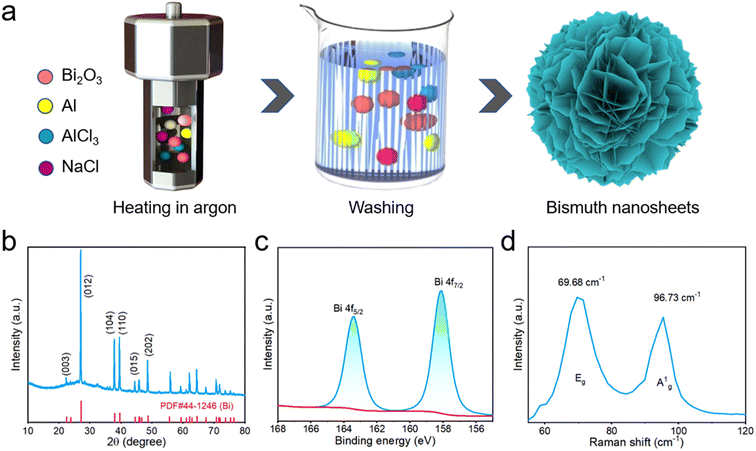 | ||
| Fig. 1 (a) Schematic illustration of the synthesis of bismuth NSs. (b) XRD pattern of the bismuth NSs. (c) XPS of bismuth NSs (d) Raman spectrum of bismuth NSs. | ||
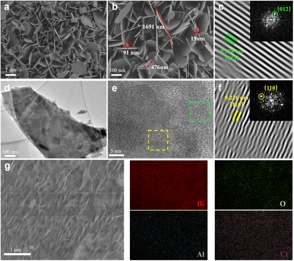
The morphology and structure of the bismuth NSs were confirmed through scanning electron microscopy (SEM) and transmission electron microscopy (TEM) analysis. The size of the prepared nanosheets ranged from 90 to 1700 nm, while their thickness was approximately 20 nm (Fig. 2a and b). In contrast, the commercial Bi powder exhibited nonuniform particles with varying sizes, as depicted in Fig. S3a and S3b.† The TEM images in Fig. 2d and e further confirms the nanosheet structure of the material. The high-resolution TEM (HRTEM) images in Fig. 2c and f reveal perfect lattice fringes at 0.328 nm and 0.226 nm (Fig. S5†), corresponding to the (012) and (110) planes of hexagonal Bi crystals. The corresponding Fast Fourier Transformation (FFT) pattern, shown in the inset, further confirms the successful fabrication of bismuth NSs, as evidenced by the presence of symmetric hexagonal spots. Additionally, the energy dispersive spectroscopy (EDS) mapping image (Fig. 1h) was utilized to analyze the distribution of Bi and O elements in the bismuth NSs (Fig. 2g). The mass proportion of the elements was determined, revealing that bismuth accounted for 92.6% of the composition (Fig. S4 and Table S1†). This analysis indicates that the main component of the material is bismuth, although it should be noted that the presence of oxygen may be attributed to surface adsorption and oxidation of the bismuth NSs, which is inevitable.
The impact of different temperatures on the prepared samples was also investigated and denoted as Bi-T, where T represents the reaction temperature. The samples were synthesized at four different temperatures: 250 °C, 300 °C, 350 °C and 400 °C. X-ray diffraction (XRD) analysis (Fig. S9†) confirmed that all final products were bismuth. Scanning electron microscopy (SEM) results demonstrated that the bismuth nanosheets became thinner and smaller as the temperature increased within a certain range (Fig. S10†). Further increasing the temperatures, the nanosheets became thicker probably because of the low melting point of bismuth. Subsequently, we assembled and tested cells separately. Among them, the Bi-350 sample, which exhibited the thinnest thickness and uniform structure, outperformed the other temperature variants at a current density of 0.5 A. This superior performance of the Bi-350 sample is illustrated in Fig. S11.† The reason is that the thinner nanosheet structure provides a larger specific surface area. It provides richer active sites for sodium ion storage and redox reactions, and shortens the electrical transport and ion diffusion distance.23,30 This means that it can exhibit good cycling stability and rate performance.
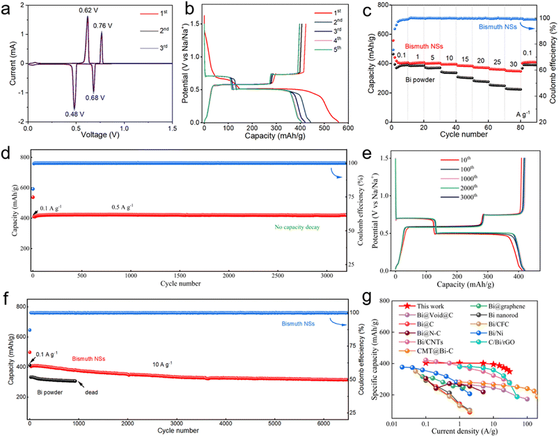
The electrochemical properties of bismuth NSs in SIBs were assessed using a CR2032-type coin cell, and the testing was conducted within a voltage range of 0.01 to 1.5 V. As shown in Fig. 3a, the main peak is consistent with the charge/discharge curve shown in Fig. 3b. Based on previous studies, the main peak observed in the cyclic voltammetry (CV) curve corresponds to the formation or appearance of different phases in the phase diagram. The cathodic peaks at 0.68 V and 0.48 V are attributed to the formation of NaBi and Na3Bi alloys, respectively. The anodic peaks at 0.62 V and 0.76 V represent the sodium extraction from Bi (Na3Bi → NaBi → Bi). The CV curve shows minimal changes, indicating a high level of reversibility and stability. The initial coulombic efficiency was measured to be 75.6%, and the initial capacity loss can be primarily attributed to the decomposition of the electrolyte, leading to the formation of the solid–electrolyte interface (SEI).31,32 The specific capacity achieved after stable cycling reached 400.6 mA h g−1, surpassing the theoretical capacity of bismuth (385 mA h g−1). This enhanced capacity can be attributed to the oxidation of bismuth nanosheets on the surface, resulting in the formation of bismuth oxide, which contributed to a portion of the overall capacity.17,33 The bismuth NSs exhibited remarkable stability during 3000 cycles of operation at a current density of 0.5 A g−1, with minimal capacity decay (Fig. 3d and e). Furthermore, even after 6500 cycles at a high current density of 10 A g−1, the capacity decay rate remained as low as 22% (Fig. 3f). In comparison, the commercial bismuth nanoparticles only achieved a specific capacity of 330 mA h g−1 at a current density of 10 A g−1 and could only sustain less than 1000 cycles. The high specific capacity and capacity retention of the bismuth NSs underscores their excellent utilization and stability.
The bismuth NSs also exhibit excellent rate capability (Fig. 3c). High specific capacities of 404.2, 404.3, 403.8, 396.1, 385.7, 361.4 and 348.6 mA h g−1 were maintained at current densities of 0.1, 1, 5, 10, 15, 20, 25 and 30 A g−1. When the current density returns to 0.1 A g−1, the electrode can still show a stable capacity of about 403.2 mA h g−1. As a comparison, commercial bismuth powder can only provide a specific capacity of 363.4 mA h g−1 at a current density of 0.1 A g−1, and a specific capacity of 225.3 mA h g−1 at a current density of 30 A g−1. The capacity retention rate is only 62% (87% for bismuth NSs). In comparison to previously reported bismuth-based anodes (Fig. 3g), bismuth NSs also exhibit a distinct advantage.21,22,34–42
Furthermore, the reaction mechanism of bismuth NSs electrodes was explored. Firstly, the cyclic voltammetry curves at different scan rates were tested. The relationship between peak current (i) and voltage scan rate (v) can be expressed as the formula:43
| i = avb |
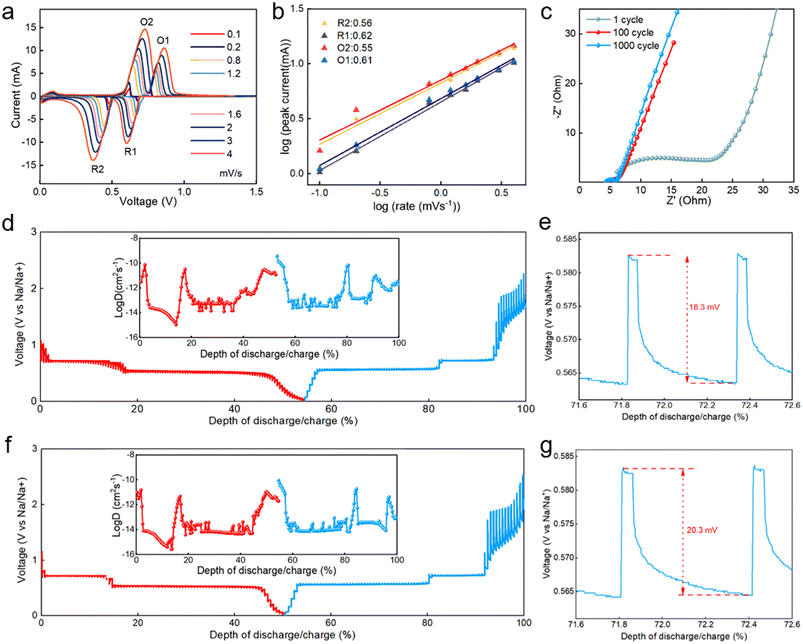
The value of b can be determined from the relationship of log(i) to log(v). According to the reported literature, the closer b value is to 0.5, it indicates that the battery performance is limited by diffusion-controlled behavior, and the closer b value is to 1.0, it indicates that the battery behavior is determined by a capacitor-like process (surface-driven behavior).44,45 At a scan rate of 0.1–4 mV, the calculated b-values of the two anodic peaks and two cathodic peaks of the bismuth NSs electrode are 0.61, 0.55, 0.62, and 0.56, respectively (Fig. 4a and b), indicating that the charge storage process is a mixture of surface capacitance-based process and diffusion-controlled battery behavior. Further EIS tests were performed to test the resistance of charge transfer (Rct) of the bismuth NSs electrode at 1100 and 1000 cycles (Fig. 4c), and the Rct were 38.36, 2.96 and 1.78 Ω, respectively (Table S2†). This suggests that repeated expansion/contraction did not pulverize the actives and also kept the surface SEI intact.46 The impedance of the first cycle was significantly smaller than that of commercial bismuth powder (Fig. S6†). This suggests that compared with the large bismuth particles, the sheet-like nanostructure allows the electrolyte to penetrate into the interstitial space of bismuth more easily to minimize the surface energy. This enables the facile transport of electrons and Na+ across the entire electrode and enables fast kinetics (excellent rate performance) and long-term cycling stability.
To further research the electrochemical reaction kinetics of the bismuth NSs electrode, we utilized galvanostatic intermittent titration technique (GITT) measurements. The bismuth NSs and commercial Bi powder electrodes were discharged/charged at a current pulse of 50 mA g−1 for a duration period of 6 min, followed by an open-circuit stand for 60 min to allow full relaxation to a quasi-equilibrium potential. The bismuth NSs electrode had a lower voltage variation in the plateau, and the coulombic efficiency was nearly 100%, suggesting that the sodiation/desodiation processes are kinetically fast and close to equilibrium (Fig. 4d). The ionic diffusion coefficient for bismuth NSs electrode as a function of voltage can be determined by the following equation:
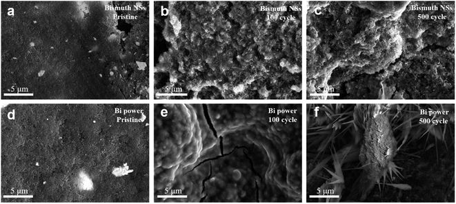 | ||
| Fig. 5 (a–c) The surface SEM images of bismuth NSs electrodes at pristine, 100 and 500 cycles. (d–f) The surface SEM images of commercial bi powder electrodes at pristine, 100 and 500 cycles. | ||
Fig. 5 presents the surface of bismuth NSs electrode and commercial Bi powder electrode after cycling (discharged to 0.1 V). It can be observed that the bismuth NSs maintained their original shape even after 100 cycles (Fig. 5b), whereas the commercial Bi powder electrode exhibited noticeable cracks after the same number of cycles (Fig. 5e). Furthermore, after 500 cycles, the electrode composed of commercial Bi powder showed sodium ion accumulation (Fig. 5f, S12, S13 and Table S2†), whereas the bismuth NSs electrode maintained a relatively intact morphology (Fig. 5c). This result indicates that the nanosheet structure of bismuth NSs mitigates the volume effects that arise from repeated expansion and contraction, thereby ensuring the structural stability throughout cycling process.
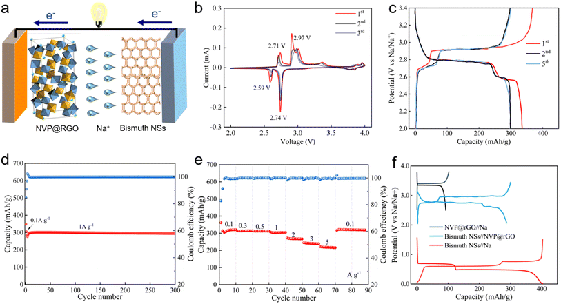
To assess the performance of the bismuth NSs anode in the full battery system, a sodium-ion full battery was constructed by coupling the bismuth NSs anode with a homemade Na3V2(PO4)3/rGO (NVP@rGO) cathode, denoted as bismuth NSs//NVP@rGO (Fig. 6a). The synthesis of NVP@rGO is illustrated in Fig. S7,† and the cathode-based NVP@rGO//Na half-cell exhibited a high voltage plateau and stable cycling performance (Fig. S8†). The bismuth NSs//NVP@rGO full cell was tested within a voltage range of 2 to 3.4 V and displayed two flat voltage plateaus at 2.7 and 2.9 V, respectively (Fig. 6b). The electrochemical reversibility of the bismuth NSs//NVP@rGO full cell was validated by the redox couples at 2.6/2.7 V and 2.7/2.9 V through CV measurements (Fig. 6b). Furthermore, the overlapping CV and charge/discharge curves in selected cycles indicated good cycling stability of the bismuth NSs//NVP@rGO full cell (Fig. 6c). Emphasizing the exceptional performance of the anode component, the current density and capacity of the full cell were based solely on the anode mass. As depicted in Fig. 6e, the bismuth NSs//NVP@rGO full cell exhibited remarkable rate capacity, achieving a high reversible capacity of 200 mA h g−1 even at a high current density of 5 A g−1. Notably, after 300 cycles, the full cell demonstrated a high reversible capacity of 300 mA h g−1 with virtually no capacity decay (Fig. 6d). This excellent rate and cycling performances of the full cell highlight the potential of the bismuth NSs anode for practical applications in SIBs.
4. Conclusion
In conclusion, we successfully synthesized novel bismuth NSs through a molten-salt-assisted aluminothermic reduction method. The unique structure of these nanosheets offers several advantages, including effective buffering of volume changes during sodiation/desodiation and enhanced diffusion of sodium ions. As an anode material for SIBs, the bismuth NSs demonstrated exceptional performance, exhibiting high-rate capability (348.6 mA h g−1 at a current density of 30 A g−1) and outstanding cycling stability (315 mA h g−1 after 6500 cycles at a current density of 10 A g−1). These remarkable results can be attributed to the 3D hierarchical structure of the bismuth nanosheets, which provide abundant active sites and a larger interlayer spacing (C-axis spacing) to facilitate the embedding and detachment of sodium ions. This study highlights the significance of small-sized sheet-like structures in promoting faster ion and electron transport rates compared to larger particles. Overall, our findings not only demonstrate the efficacy of nano-sized sheet structures in improving the rate and cycling performance of anode materials but also offer valuable insights for the development of advanced materials for high-performance SIBs and other rechargeable batteries.Author contributions
K. Hu conducted the main writing and carried out the experimental aspects of the manuscript. Y. Chen and K. Fan contributed to shaping the direction of the article. X. Du, C. Zheng, M. Wang, and Q. Yao assisted with the testing phase of the research. H. Wang, W. Wang, and X. Yan provided support in conducting specific experiments. Nana Wang contributed to the revision process of the article. Z. Bai and S. Dou supervised the article and played a key role in designing the experiments.Conflicts of interest
There are no conflicts to declare.Acknowledgements
This work was financially supported by the National Nature Science Foundation of China (No. 22272093) and Natural Science Foundation of Shandong Province (ZR2021MB127).References
- G. Assat and J.-M. Tarascon, Nat. Energy, 2018, 3, 373–386 CrossRef CAS
.
- M. Winter, B. Barnett and K. Xu, Chem. Rev., 2018, 118, 11433–11456 CrossRef CAS PubMed
.
- M. Li, J. Lu, Z. Chen and K. Amine, Adv. Mater., 2018, 30, 1800561 CrossRef PubMed
.
- K. Chayambuka, G. Mulder, D. L. Danilov and P. H. L. Notten, Adv. Energy Mater., 2020, 10, 2001310 CrossRef CAS
.
- H. Wang, C. Zhu, J. Liu, S. Qi, M. Wu, J. Huang, D. Wu and J. Ma, Angew. Chem., 2022, 134, e202208506 CrossRef
.
- D. Wu, C. Zhu, M. Wu, H. Wang, J. Huang, D. Tang and J. Ma, Angew. Chem., Int. Ed., 2022, 61, e202214198 CrossRef CAS PubMed
.
- C. Zhu, D. Wu, Z. Wang, H. Wang, J. Liu, K. Guo, Q. Liu and J. Ma, Adv. Funct. Mater., 2023, 2214195 CrossRef
.
- N. Wang, Y. Wang, Z. Bai, Z. Fang, X. Zhang, Z. Xu, Y. Ding, X. Xu, Y. Du and S. Dou, Energy Environ. Sci., 2020, 13, 562–570 RSC
.
- P. Xue, N. Wang, Z. Fang, Z. Lu, X. Xu, L. Wang, Y. Du, X. Ren, Z. Bai and S. Dou, Nano Lett., 2019, 19, 1998–2004 CrossRef CAS PubMed
.
- N. Wang, Z. Bai, Y. Qian and J. Yang, Adv. Mater., 2016, 28, 4126–4133 CrossRef CAS PubMed
.
- Y. Fang, X.-Y. Yu and X. W. D. Lou, Matter, 2019, 1, 90–114 CrossRef
.
- P. Tsai, S.-C. Chung, S. Lin and A. Yamada, J. Mater. Chem. A, 2015, 3, 9763–9768 RSC
.
- L. Xiao, Y. Cao, W. A. Henderson, M. L. Sushko, Y. Shao, J. Xiao, W. Wang, M. H. Engelhard, Z. Nie and J. Liu, Nano Energy, 2016, 19, 279–288 CrossRef CAS
.
- S. Qiu, L. Xiao, M. L. Sushko, K. S. Han, Y. Shao, M. Yan, X. Liang, L. Mai, J. Feng, Y. Cao, X. Ai, H. Yang and J. Liu, Adv. Energy Mater., 2017, 7, 1700403 CrossRef
.
- H. Zhang, I. Hasa and S. Passerini, Adv. Energy Mater., 2018, 8, 1702582 CrossRef
.
- L. D. Ellis, B. N. Wilkes, T. D. Hatchard and M. N. Obrovac, J. Electrochem. Soc., 2014, 161, A416–A421 CrossRef CAS
.
- J. Sun, M. Li, J. A. S. Oh, K. Zeng and L. Lu, Mater. Technol., 2018, 33, 563–573 CrossRef CAS
.
- H. Gao, W. Ma, W. Yang, J. Wang, J. Niu, F. Luo, Z. Peng and Z. Zhang, J. Power Sources, 2018, 379, 1–9 CrossRef CAS
.
- J. Sottmann, M. Herrmann, P. Vajeeston, Y. Hu, A. Ruud, C. Drathen, H. Emerich, H. Fjellvåg and D. S. Wragg, Chem. Mater., 2016, 28, 2750–2756 CrossRef CAS
.
- Y. Huang, C. Zhu, S. Zhang, X. Hu, K. Zhang, W. Zhou, S. Guo, F. Xu and H. Zeng, Nano Lett., 2019, 19, 1118–1123 CrossRef CAS PubMed
.
- S. Liu, J. Feng, X. Bian, J. Liu and H. Xu, J. Mater. Chem. A, 2016, 4, 10098–10104 RSC
.
- F. Yang, F. Yu, Z. Zhang, K. Zhang, Y. Lai and J. Li, Chem. Eur. J., 2016, 22, 2333–2338 CrossRef CAS PubMed
.
- H. Tao, Q. Fan, T. Ma, S. Liu, H. Gysling, J. Texter, F. Guo and Z. Sun, Prog. Mater. Sci., 2020, 111, 100637 CrossRef CAS
.
- J. Zhu, J. Wang, G. Li, L. Huang, M. Cao and Y. Wu, J. Mater. Chem. A, 2020, 8, 25746–25755 RSC
.
- P. Xiong, P. Bai, A. Li, B. Li, M. Cheng, Y. Chen, S. Huang, Q. Jiang, X.-H. Bu and Y. Xu, Adv. Mater., 2019, 31, 1904771 CrossRef CAS PubMed
.
- L. Yi, J. Chen, P. Shao, J. Huang, X. Peng, J. Li, G. Wang, C. Zhang and Z. Wen, Angew. Chem., Int. Ed., 2020, 59, 20112–20119 CrossRef CAS PubMed
.
- F. Li, Y.-E. Zhu, J. Sheng, L. Yang, Y. Zhang and Z. Zhou, J. Mater. Chem. A, 2017, 5, 25276–25281 RSC
.
- Y. Pan, L. Gong, X. Cheng, Y. Zhou, Y. Fu, J. Feng, H. Ahmed and H. Zhang, ACS Nano, 2020, 14, 5917–5925 CrossRef CAS PubMed
.
- H. Li, Q. Zhang, C. C. R. Yap, B. K. Tay, T. H. T. Edwin, A. Olivier and D. Baillargeat, Adv. Funct. Mater., 2012, 22, 1385–1390 CrossRef CAS
.
- Y. Zhu, L. Peng, Z. Fang, C. Yan, X. Zhang and G. Yu, Adv. Mater., 2018, 30, 1706347 CrossRef PubMed
.
- K. Xu, Chem. Rev., 2004, 104, 4303–4418 CrossRef CAS PubMed
.
- K. Xu, Chem. Rev., 2014, 114, 11503–11618 CrossRef CAS PubMed
.
- X. Li, J. Ni, S. V. Savilov and L. Li, Chem. – Eur. J., 2018, 24, 13719–13727 CrossRef CAS PubMed
.
- D. Su, S. Dou and G. Wang, Nano Energy, 2015, 12, 88–95 CrossRef CAS
.
- C. Hu, Y. Zhu, G. Ma, F. Tian, Y. Zhou, J. Yang and Y. Qian, Electrochim. Acta, 2021, 365, 137379 CrossRef CAS
.
- H. Yang, L.-W. Chen, F. He, J. Zhang, Y. Feng, L. Zhao, B. Wang, L. He, Q. Zhang and Y. Yu, Nano Lett., 2020, 20, 758–767 CrossRef CAS PubMed
.
- L. Wang, C. Wang, F. Li, F. Cheng and J. Chen, Chem. Commun., 2018, 54, 38–41 RSC
.
- S. Liu, Z. Luo, J. Guo, A. Pan, Z. Cai and S. Liang, Electrochem. Commun., 2017, 81, 10–13 CrossRef CAS
.
- Y. Wang, Y. Ding, J. Gao, X. Zhang, H. Sun and G. Wang, J. Colloid Interface Sci., 2023, 643, 420–427 CrossRef CAS PubMed
.
- B. Park, S. Lee, D.-Y. Han, H. Jang, D. Gi Seong, J.-K. Yoo, S. Park, Y. Oh and J. Ryu, Appl. Surf. Sci., 2023, 614, 156188 CrossRef CAS
.
- R. Ababaikeri, Y. Sun, X. Wang, X. Li, M. Li, F. Zhang, Y. Li, P. Wang, J. Guo and Y. Cao, J. Alloys Compd., 2023, 935, 168207 CrossRef CAS
.
- P. Xiong, P. Bai, A. Li, B. Li, M. Cheng, Y. Chen, S. Huang, Q. Jiang, X.-H. Bu and Y. Xu, Adv. Mater., 2019, 31, 1904771 CrossRef CAS PubMed
.
- J. Zhu, J. Fan, T. Cheng, M. Cao, Z. Sun, R. Zhou, L. Huang, D. Wang, Y. Li and Y. Wu, Nano Energy, 2020, 75, 104939 CrossRef CAS
.
- F. Jiang, R. Du, X. Yan, M. Zhang, Q. Han, X. Sun, X. Zhang and Y. Zhou, Electrochim. Acta, 2020, 329, 135146 CrossRef CAS
.
- H.-S. Kim, J. B. Cook, H. Lin, J. S. Ko, S. H. Tolbert, V. Ozolins and B. Dunn, Nat. Mater., 2017, 16, 454–460 CrossRef CAS PubMed
.
- Z. Xu, J. Yang, T. Zhang, L. Sun, Y. Nuli, J. Wang and S. Hirano, Adv. Funct. Mater., 2019, 29, 1901924 CrossRef
.
Footnote |
| † Electronic supplementary information (ESI) available. See DOI: https://doi.org/10.1039/d3ra03767c |
| This journal is © The Royal Society of Chemistry 2023 |

