 Open Access Article
Defect- and oxygen-rich nanocarbon derived from solution plasma for bifunctional catalytic activity of oxygen reduction and evolution reactions†
Hye-min Kima,
Byung-chul Chab and
Dae-wook Kim *b
*b
aDepartment of Materials Chemistry, Shinshu University, 4-17-1, Wakasato, Nagano, 3808553, Japan
bAdvanced Manufacturing Process R&D Group, Ulsan Regional Division, Korea Institute of Industrial Technology (KITECH), 55, Jongga-ro, Jung-gu, Ulsan, 44313, Korea. E-mail: dwkim@kitech.re.kr
First published on 7th September 2023
Abstract
The oxygen reduction reaction (ORR) and oxygen evolution reaction (OER) are key for renewable energy systems, including metal–air batteries, fuel cells, and water electrolysis. In particular, metal–air batteries require multiple catalysts for the ORR and OER. Thus, bifunctional catalysts are required to improve efficiency and simplify catalytic systems. Hence, we developed defect- and oxygen-rich nanocarbons as bifunctional catalysts through a one-pot formation by applying plasma discharge in mixed solvents of benzene with crown ether. Raman and X-ray photoelectron spectroscopy results confirmed that oxygen was embedded and functionalized into the carbon matrix and abundant defects were formed, which highly affected the catalytic activity of the ORR and OER. The obtained CNP-CEs revealed a tuned electron transfer trend to a rapid four-electron pathway (n = 3.5) for the ORR, as well as a decreased onset potential and Tafel slope for the OER. Consequently, CNP-CE-50 exhibited an improved bifunctional catalytic characteristic with the narrowest potential gap between the ORR and OER. We believe that our findings suggest new models for carbon-based bifunctional catalysts and provide a prospective approach for a synthetic procedure of carbon nanomaterials.
1. Introduction
To overcome global warming, new technologies are required for renewable and environment-friendly energy systems. Recently, studies on energy storage and conversion devices, including fuel cells, secondary batteries, metal–air batteries, and water electrolysis have been attempted and increased progressively.1–5 To improve the efficiency of the aforementioned devices, appropriate catalysts are required for applications. In addition, several devices require multiple catalysts for different reactions between the cathode and anode. Thus, simultaneously useable bifunctional catalysts could improve the performance and economic efficiency of cathode and anode reactions.Metal–air batteries are driven by continuous reactions between the cathode and anode. To enhance their performance, catalysts are required for the oxygen reduction reaction (ORR) and oxygen evolution reaction (OER) at the cathode and anode, respectively. Nanostructured Pt and RuO2 or IrO2 are considered the best catalysts for the ORR and OER, respectively.6–8 However, limited resources and their high cost can diminish their performance merits. In addition, the agglomeration, sintering, and decomposition of catalysts occur during long-term operation. Thus, to resolve these drawbacks, heteroatom-doped carbon-based materials are considered effective metal-free catalysts.9,10 Doping has been attempted using nitrogen, boron, phosphorus, sulfur, oxygen, and fluorine to improve catalytic activity.11–15 Heteroatom-doped carbon reduces oxygen molecules through the following mechanism. Owing to a difference in electronegativity and the atomic radius, the charge neutrality is broken, and neighboring sites enter the charge-delocalized state with defects, which can be active sites.11,16,17
In the case of oxygen as a dopant, its high electronegativity, compared with that of carbon, could reveal a behavior similar to that of other dopants. Moreover, oxygen-containing functional groups with abundant defects can efficiently adsorb oxygen molecules and oxygenated intermediates, which would facilitate the ORR and OER.18,19 Various approaches have been employed to introduce oxygen-containing functional groups into the carbon matrix.14,18,20,21 Among these approaches, the oxygen plasma treatment is the most used. Due to oxygen plasma, the oxygen contents are effectively doped or functionalized, which increases catalytic activity.14,18 Although this is an effective route to enhancing catalytic activity, multiple steps (carbon material synthesis and plasma modification) are required in a vacuum environment. Via another route, chemical synthesis is also applied using oxygen-containing organic molecules. However, this alternative route requires template materials and oxidation steps with a long processing time.21
Hence, we employed a prospective synthesis method, named the solution plasma process (SPP), for oxygen-embedded and -functionalized nanocarbon materials. Solution plasma is a type of nonequilibrium and cold plasma in the liquid phase. During discharge, highly active species and energetic electrons promote rapid reaction kinetics.22–25 SPP has been employed to synthesize nanocarbon, metal oxide, and nanocomposites.26–28 Here, SPP was applied in an 18-crown-6 ether-added benzene precursor to embed and functionalize oxygen into the inside and edge of the carbon structure with abundant defects. The products were synthesized through the dissociation and recombination of benzene and 18-crown-6 ether. The obtained catalysts exhibited improved catalytic activity in the ORR and OER. The effect of introduced oxygen and defect sites on the bifunctional catalytic activity and their role was investigated. Thus, this report provides a route to the rational design of bifunctional catalysts using oxygen functional groups in the carbon matrix.
2. Experimental
2.1 Material synthesis
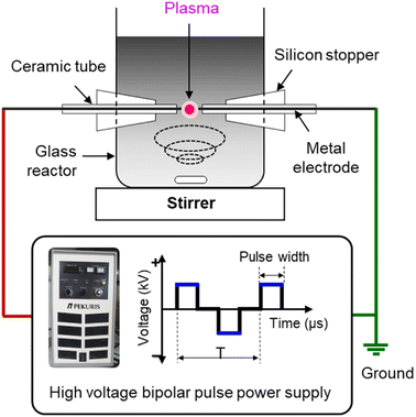
Defect and oxygen-rich nanocarbon was synthesized by SPP in mixed oxygen-containing organic solvents. Benzene (C6H6, Kanto Chemical) and dicyclohexano-18-crown-6 ether (C20H36O6, crown ether (CE), Tokyo Chemical Industry) were used as carbon and oxygen sources, respectively. To control the oxygen content with defects, various CE concentrations (10, 20, and 50 mM) were added to the benzene solvents. The obtained particles were denoted CNP-CE-10, CNP-CE20, and CNP-CE50, respectively. Pure carbon, CNP, was compared as a reference.To generate solution plasma, a pair of tungsten rods (outer diameter (o.d.), 1 mm) were used as the electrodes, and a voltage of 1.2 kV was applied using a bipolar pulsed power generator (MPP04, Kurita) for 10 min. The pulse width and frequency were fixed to 0.8 μs and 25 kHz, respectively. The schematic experimental setup is shown in Fig. 1. After plasma discharge, the obtained suspension was filtrated and dried in a vacuum oven at 80 °C for 24 h.
2.2 Characterization
The structural properties were analyzed by X-ray diffraction (XRD; ULTIMA 4, Rigaku) with Cu Kα (λ = 1.5418 Å) and Raman spectroscopy (NEXSA, Thermo Scientific) with 532 nm laser power. To investigate the morphologies of the obtained materials, field-emission scanning electron microscopy (FE-SEM; SU8020, Hitachi) and transmission electron microscopy (TEM; JEL-2100F, JEOL) were performed. The specific surface area and pore structure were observed by nitrogen adsorption/desorption isotherms (3-Flex, Micromeritics) using the Brunauer–Emmett–Teller (BET) and Barrett–Joyner–Halenda (BJH) methods. X-ray photoelectron spectroscopy (XPS; NEXSA, Thermo Scientific, monochromatic Al Kα) was conducted to examine the surface chemical compositions and chemical bonding. The electrical resistivity was conducted by four-point probe method (CMT-SR1000N, AIT).2.3 Electrochemical measurements
Electrochemical measurements were conducted using a multi-potentiostat (ZIVE MP2A, WonATech) with a three-electrode system. Pt wire, Ag/AgCl, and glassy carbon were used as the counter, reference, and working electrodes, respectively. To prepare the working electrode, 20 μL of catalyst ink was drop-cast onto the glassy carbon. Typically, the catalyst (5 mg) was dispersed in ethanol (0.5 mL), and a Nafion ionomer (50 μL, 5 wt%, Sigma Aldrich) was added. The mixture was sonicated for 30 min to obtain homogeneous ink. To examine the ORR and OER activity, cyclic voltammetry (CV) and linear sweep voltammetry (LSV) were performed. The CV curves were obtained within a range of −1.0 to 0.3 V (V vs. Ag/AgCl) at a scan rate of 20 mV s−1 in N2- and O2-saturated 0.1 M KOH. LSV measurements were conducted for the ORR and OER using a rotating disk electrode (RDE) at the scan rate of 10 mV s−1 with a rotation speed of 2000 rpm in the ranges of −1.0 to 0.2 V and 0.2–1.0 V (V vs. Ag/AgCl), respectively.3. Results and discussion
3.1 Synthetic mechanism
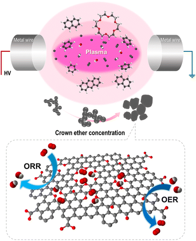
We previously reported that the formation of nanocarbon particles was achieved via the dissociation and reconstruction reaction in aromatic hydrocarbon solvents. Owing to plasma discharge, energetic electrons and reactive species decompose solvents, and generated radicals, such as C2 and CH, reconstruct with the surrounding intermediates.25,29 To introduce oxygen and create defects, CE was used as an oxygen precursor with a defect promoter. The CE was decomposed and generated radicals, including O, C2, H, and CH, in the plasma core region. Simultaneously, the oxygen-containing intermediates derived from CE decomposition incorporated into carbon matrix and functionalized on the edge of carbon. Furthermore, it did not completely decompose, thereby generating partially decomposed and only C–H-activated cationized CE because of the low energy at the plasma/liquid interface. The activated CE was also reconstructed with small polycyclic aromatic hydrocarbon and incorporated into carbon matrix. Thus, the oxygen was embedded and functionalized with numerous defects within the carbon matrix. The proposed synthetic mechanism is shown in Fig. 2. To clarify this hypothesis, the chemical bonding structure and structural deformation were investigated.3.2 Characterization
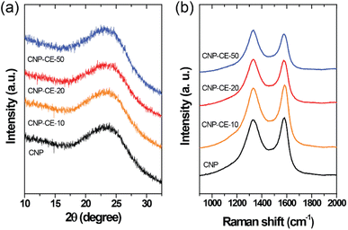
The structural characteristics were investigated by XRD and Raman measurements. The XRD patterns of the CNP and CNP-CEs are shown in Fig. 3a. The graphitic carbon (002) diffraction was mainly focused to confirm the degree of graphitization. With an increase in CE concentration, the (002) diffraction peak slightly broadened, whereas the peak position of the (002) diffraction slightly shifted toward a lower 2θ angle. The expansion of the interplanar spacing (d002) might have originated from the oxygen with defects incorporated into the carbon lattice. The increased CE further induced deformation in the carbon structure. Fig. 3b shows the Raman spectra of the CNP and CNP-CEs as a function of the CE concentration. As expected, CNP exhibited the lowest ID/IG value among all the prepared particles. Due to the addition of CE, the ID/IG value gradually increased with an increase in CE. CNP-CE-50 exhibited the highest ID/IG value, which significantly increased compared with that of CNP. The D peak corresponded to a distortion of the graphitic lattice;30 therefore, a high ID/IG value implied more defects within the carbon matrix. In addition, the average defect distance (LD) and defect density (nD) were calculated using the following equation.31,32| LD2 (nm2) = 1.8 × 10⁻⁹λL4 (ID/IG)−1 |
where λL is the excitation laser wavelength of the Raman laser source. These equations were valid for point defects rather than edge defects. The calculated LD and nD with the ID/IG values are summarized in Table 1. Due to an increase in the CE concentration, the LD and nD decreased and increased, respectively, suggesting the formation of more defects within the carbon matrix. The obtained results were consistent with the XRD results, confirming that the oxygen atoms were successfully embedded and functionalized into the carbon matrix and led to the formation of abundant defects. The embedment of hetero atoms and numerous defect sites could affect electronic structure of CNP. To clarify these effects, the electrical resistivity was examined. As reference, CNP exhibited 84 Ω cm. Owing to introduce CE, the resistivity was slightly decreased to 70 Ω cm at CNP-CE-50. The resistivity values of CNP-CE-10 and -20 were 79 and 76 Ω cm, respectively. The improved conductivity could contribute to catalytic activity.
| Samples | ID/IG | LD (nm) | nD (cm−2) |
|---|---|---|---|
| CNP | 0.88 | 12.80 | 1.97 × 10¹¹ |
| CNP-CE-10 | 0.94 | 12.38 | 2.11 × 10¹¹ |
| CNP-CE-20 | 1.01 | 11.94 | 2.26 × 10¹¹ |
| CNP-CE-50 | 1.04 | 11.77 | 2.34 × 10¹¹ |
The morphology of the CNP and CNP-CEs was investigated by electron microscopy. FE-SEM images (Fig. 4a–d) revealed that the CNP and CNP-CEs exhibited homogeneous shape and size distribution. TEM images (Fig. 4e–h) showed that the particle size gradually increased with an increase in the CE concentration from ca. 20 nm to ca. 60 nm. In addition, their spherical-like shape began to slowly transform into a sheet-like shape with the addition of CE. These morphological changes might be originated from the generated O radicals and cationized CE during plasma discharge. During reconstruction, partially decomposed and C–H-activated CE was polymerized with polycyclic aromatic hydrocarbon intermediates, and O radicals induced more hexagon ring structures, resulting in gradual growth into a sheet-like structure.25,33
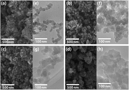 | ||
| Fig. 4 FE-SEM and TEM images of CNP (a, e), CNP-CE-10 (b, f), CNP-CE-20 (c, g), and CNP-CE-50 (d, h). | ||
The effect of the morphological features on the specific surface area (SSA) with the pore structure was investigated using the BET method (Fig. S1†). The measured SSA values are summarized in Table S1.† The SSA and pore volume of CNP were 149 m2 g−1 and 1.57 cm3 g−1, respectively. The addition of CE slightly increased the SSA and pore volume to 169–173 m2 g−1 and 1.77–1.83 cm3 g−1, respectively, which might be attributed to the creation of several defects in the matrix.
XPS analysis was performed to investigate the chemical bonding and the effect on active sites (Fig. 5). In the survey spectra, carbon and oxygen peaks were detected without any element, and the chemical composition changed with the CE concentration (Fig. 5a). In the C 1s core-level spectra (Fig. 5b), the spectra were deconvoluted into five peaks, which were assigned to C![[double bond, length as m-dash]](https://www.rsc.org/images/entities/char_e001.gif) C (284.4 ± 0.2 eV), C–C/C–H (285.3 ± 0.2 eV), C–O (286.4 ± 0.2 eV), C
C (284.4 ± 0.2 eV), C–C/C–H (285.3 ± 0.2 eV), C–O (286.4 ± 0.2 eV), C![[double bond, length as m-dash]](https://www.rsc.org/images/entities/char_e001.gif) O (287.4 ± 0.2 eV), and O–C
O (287.4 ± 0.2 eV), and O–C![[double bond, length as m-dash]](https://www.rsc.org/images/entities/char_e001.gif) O (288.8 ± 0.2 eV).34 Due to the addition of CE, the sp3 carbon bond relatively increased compared with that of CNP. The ratio of sp3 carbon increased with an increase in CE. An association between decomposed C2 radicals and CE intermediates during the discharge might have caused an increase in sp3 hybridization. Fig. 5c shows the O 1s core-level spectra. The three deconvoluted peaks were assigned to –OH (533.7 ± 0.3 eV), C–O (532.2 ± 0.3 eV), and C
O (288.8 ± 0.2 eV).34 Due to the addition of CE, the sp3 carbon bond relatively increased compared with that of CNP. The ratio of sp3 carbon increased with an increase in CE. An association between decomposed C2 radicals and CE intermediates during the discharge might have caused an increase in sp3 hybridization. Fig. 5c shows the O 1s core-level spectra. The three deconvoluted peaks were assigned to –OH (533.7 ± 0.3 eV), C–O (532.2 ± 0.3 eV), and C![[double bond, length as m-dash]](https://www.rsc.org/images/entities/char_e001.gif) O (530.3 ± 0.3 eV).35 With an increase in the CE concentration, the bonding ratio changed, which tended to increase the C–O bonding from 57 to 78%. The –OH species decreased from 39 to 19%. The increase in C–O bonding might arise from the embedded and functionalized ether groups derived from the CE molecules. The XPS core-level results revealed good agreement between the C 1s and O 1s spectra. The increased embedded and functionalized oxygen could be an active site for the ORR, which might facilitate electrocatalytic reactions.36,37
O (530.3 ± 0.3 eV).35 With an increase in the CE concentration, the bonding ratio changed, which tended to increase the C–O bonding from 57 to 78%. The –OH species decreased from 39 to 19%. The increase in C–O bonding might arise from the embedded and functionalized ether groups derived from the CE molecules. The XPS core-level results revealed good agreement between the C 1s and O 1s spectra. The increased embedded and functionalized oxygen could be an active site for the ORR, which might facilitate electrocatalytic reactions.36,37
3.3 Electrochemical characteristics
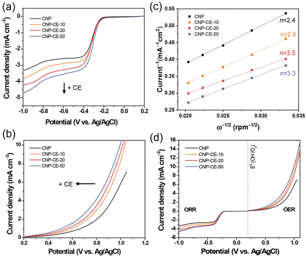
To investigate catalytic activity toward the ORR, CV was conducted in an N2- and O2-saturated 0.1 M KOH electrolyte at a scan rate of 20 mV s−1 (Fig. 6). A cathodic peak and onset potential corresponding to the ORR were detected at −0.285 and −0.193 V, respectively, for CNP (Fig. 6). Due to the addition of CE, oxygen-embedded and -functionalized sites with abundant defects were formed within the carbon matrices, which highly affected the ORR activity. Compared with CNP, the CNP-CEs exhibited significantly enhanced ORR catalytic activity. The cathodic peak and onset potential were shifted to higher potentials of −0.254 and −0.154 V, respectively. Furthermore, the current density of the ORR for CNP-CE-50 was more than two times higher than that of CNP. Among the CNP-CEs, the ORR potential had similar values, whereas the current density gradually increased with an increase in CE. The results suggested that increasing the CE led to increased active sites for the ORR, which promoted higher current density. In addition, numerous defects formation could affect to enhance electrochemical active surface area (ECSA), which contribute to higher ORR current density (Fig. S2†). Note that the pure CE was did not show any peaks related ORR due to lack of ECSA (Fig. S3†).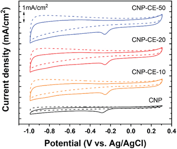 | ||
| Fig. 6 Cycle voltammetry curves of CNP and CNP-CEs at a scan rate of 20 mV in the N2 and O2 saturated 0.1 M KOH. | ||
To elucidate the electron transfer kinetics during the ORR, LSV was conducted in the O2-saturated 0.1 M KOH solution at a scan rate of 10 mV and different rotation speeds using an RDE. The measured all of LSV results are shown in Fig. S4.† As shown in Fig. 7a, the limiting current density of the CNP-CEs increased with an increase in CE from 10 to 50 mM, which was consistent with the CV results. During the ORR process, the electron transfer number (n) was determined using the Koutecký–Levich (K–L) equation.38
where j is the measured current density; jk and jL are the kinetic and diffusion-limiting current densities, respectively; ω is the disk rotation rate; n is the number of electrons transferred per oxygen molecule; F is Faraday's constant (F = 96
![[thin space (1/6-em)]](https://www.rsc.org/images/entities/char_2009.gif) 485 C); n is the number of electrons transferred per oxygen molecule;
485 C); n is the number of electrons transferred per oxygen molecule;  and D0 are the oxygen bulk concentration (1.2 × 10⁻⁶ mol cm−3) and diffusion coefficient of oxygen (1.9 × 10⁻⁵ cm2 s−1), respectively; and ν is the kinetic viscosity of the electrolyte (1.1 × 10⁻² cm2 s−1).39,40 The K–L plots revealed good linearity for all the samples, and n was calculated from the slope of the K–L plots (Fig. 7c). The calculated n of CNP was 2.4 at −0.5 V, which was close to the two-electron transfer process. Contrarily, the CNP-CEs exhibited an ORR process close to the four-electron transfer. This verified that the presence of oxygen-embedded and -functionalized sites and defects within the carbon matrices significantly improved the reaction kinetics and activity for ORR.
Interestingly, the highest n of 3.5 was observed for CNP-CE-20. This unexpected result might be originated from the oxygen content of the carbon matrices. According to previous studies, oxygen-containing functional groups frequently induce to produce hydrogen peroxide, which led to a two-electron transfer process as a dominant pathway.40,41 The XPS results indicated significant increasing oxygen contents when CE was increased from 20 to 50 mM. Thus, CNP-CE-50 involved more two-electron reactions than CNP-CE-20, resulting in a reduced n value. Although the n value was reduced, CNP-CE-50 exhibited mainly four-electron transfer processes and the highest limiting current density. An increase in CE induced the formation of more defects, which allowed more adsorption for the oxygen molecules.42–44 Consequently, high oxygen accessibility with abundant defect sites led to the utilization of more active sites and increased the reaction capacity for the ORR, which would cause a progressive increasing of the current density for CNP-CE-50.
The OER activity was examined to investigate bifunctional catalytic activity (Fig. 7b). As shown in Fig. 7b, the CNP-CEs revealed smaller onset potentials and faster elevating current densities for the OER than that of CNP. The onset potential gradually decreased with an increase in CE. Moreover, Tafel slope of CNP-CE-50 exhibited the lowest value in the prepared catalysts, indicating low overpotential, and it tends to same tendency with onset potential (Fig. S5†). This trend for the OER activity of CNP-CEs might be originated from the concentration of oxygen atoms and defects in the carbon matrix. Owing to the embedded and functionalized oxygen atoms, the surrounding site became an uneven electric charge state.14,39 Thus, the neighboring carbon atoms were positively charged by the charge redistribution.17,39 The conjugated oxygen atoms led to a positive charge, thus the neighboring carbon can be an active site for OER. The positively charged carbon facilitated the adsorption of the surrounding OH– by electrostatic forces, which efficiently evolved oxygen molecules during the OER.45 To determine the bifunctional catalytic characteristic, the potential gap (ΔE) between the ORR (at −3 mA cm−2) and OER (at 10 mA cm−2) potentials was investigated (Fig. 7d). The ΔE can be explained by the sum of overpotentials for the ORR and OER. A narrow ΔE is a criterion for determining the bifunctional catalytic characteristic. As explained, the CNP-CEs exhibited improved catalytic activity in the ORR and OER. Thus, CNP-CE-50 revealed the narrowest ΔE in the prepared all the catalyst.
Based on the aforementioned results, the addition of CE during discharge facilitated the embedment and functionalization of oxygen within the carbon matrices, which could be effective active sites for the ORR and OER. In addition, an appropriate concentration of oxygen is a critical factor for the ORR. Moreover, the formation of abundant defects facilitated the adsorption of oxygen molecules and hydroxide species, which affected to enhance bifunctional catalytic activity.
4. Conclusions
Defect and oxygen-rich nanocarbon was successfully synthesized via plasma discharge in benzene with CE. Due to the dissociation and recombination of benzene and CE, the oxygen-containing species were embedded and functionalized into the carbon matrix. Raman spectroscopy results demonstrated that the added CE effectively created defect sites. The synergetic effect between the embedded and functionalized oxygen with defects ensured sufficient catalytic activity for the ORR and OER. Moreover, the CNP-CEs presented mainly a four-electron transfer process for the ORR, and CNP-CE-20 revealed the highest n of 3.5. Besides, an added CE led to a low overpotential with a high current density for the OER. We expect that defect and oxygen-rich nanocarbon will be a new route for synthesizing bifunctional catalysts and carbon-based functional materials.Conflicts of interest
There are no conflicts to declare.Acknowledgements
This research was supported by Korea Research Fellowship program funded by the Ministry of Science and ICT through the National Research Foundation of Korea (2019H1D3A1A01071089). This study has been conducted with the support of the Korea Institute of Industrial Technology as “Support Business of Customized Production Technology for Small and Medium Enterprises (KITECH UR-23-0049)”.References
- M. K. Singla, P. Nijhawan and A. S. Oberoi, Environ. Sci. Pollut. Res. Int., 2021, 28, 15607–15626 CrossRef CAS PubMed.
- N. Zhang, T. Deng, S. Zhang, C. Wang, L. Chen, C. Wang and X. Fan, Adv. Mater., 2022, 34, e2107899 CrossRef PubMed.
- N. Sharmili, R. Nagi and P. F. Wang, J. Energy Storage, 2023, 68, 107622 CrossRef.
- S. S. Kumar and H. Lim, Sustainable Energy Fuels, 2023, 7, 3560–3583 RSC.
- R. Bianqing, J. Cao, H. Zhang, C. Han and W. Xu, Mater. Chem. Front., 2023, 7, 3209–3231 RSC.
- M. Liu, Z. Zhao, X. Duan and Y. Huang, Adv. Mater., 2019, 31, 1802234 CrossRef PubMed.
- Z. Ma, Y. Zhang, S. Liu, W. Xu, L. Wu, Y.-C. Hsieh, P. Liu, Y. Zhu, K. Sasaki and J. N. Renner, J. Electroanal. Chem., 2018, 819, 296–305 CrossRef CAS.
- H. Over, ACS Catal., 2021, 11, 8848–8871 CrossRef CAS.
- J. Quílez-Bermejo, E. Morallón and D. Cazorla-Amorós, Carbon, 2020, 165, 434–454 CrossRef.
- H. Shi, Y. Shen, F. He, Y. Li, A. Liu, S. Liu and Y. Zhang, J. Mater. Chem. A, 2014, 2, 15704–15716 RSC.
- D. Guo, R. Shibuya, C. Akiba, S. Saji, T. Kondo and J. Nakamura, Science, 2016, 351, 361–365 CrossRef CAS PubMed.
- M. Del Cueto, P. Ocón and J. Poyato, J. Phys. Chem. C, 2015, 119, 2004–2009 CrossRef CAS.
- Y. Sun, J. Wu, J. Tian, C. Jin and R. Yang, Electrochim. Acta, 2015, 178, 806–812 CrossRef CAS.
- R. Mohan, A. Modak and A. Schechter, ACS Sustain. Chem. Eng., 2019, 7, 11396–11406 CrossRef CAS.
- Y. Chang, J. Chen, J. Jia, X. Hu, H. Yang, M. Jia and Z. Wen, Appl. Catal., B, 2021, 284, 119721 CrossRef CAS.
- S. K. Singh, K. Takeyasu and J. Nakamura, Adv. Mater., 2019, 31, 1804297 CrossRef PubMed.
- J. Quílez-Bermejo, E. Morallón and D. Cazorla-Amorós, Carbon, 2020, 165, 434–454 CrossRef.
- L. Q. Li, H. B. Yang, J. W. Miao, L. P. Zhang, H. Y. Wang, Z. P. Zeng, W. Huang, X. C. Dong and B. Liu, Appl. Catal., B, 2017, 2, 294–300 CAS.
- S. W. Ham, H. P. Hong, J. H. Kim, S. J. Min and N. K. Min, J. Nanosci. Nanotechnol., 2014, 14, 8476–8481 CrossRef CAS PubMed.
- S. Ghosh, S. Barg, S. M. Jeong and K. Ostrikov, Adv. Energy Mater., 2020, 10, 20011239 Search PubMed.
- Z. X. Chen, Y. Z. Li, M. Wu and Y. L. Cao, Energy Fuel, 2021, 35, 2665–2673 CrossRef CAS.
- O. Takai, Pure Appl. Chem., 2008, 80, 2003–2011 CrossRef CAS.
- M. A. Bratescu, S.-P. Cho, O. Takai and N. Saito, J. Phys. Chem. C, 2011, 115, 24569–24576 CrossRef CAS.
- C. Chokradjaroen, X. Wang, J. Niu, T. Fan and N. Saito, Mater. Today Adv., 2022, 14, 100244 CrossRef CAS.
- T. Morishita, T. Ueno, G. Panomsuwan, J. Hieda, A. Yoshida, M. A. Bratescu and N. Saito, Sci. Rep., 2016, 6, 36880 CrossRef CAS PubMed.
- D. W. Kim, O. L. Li and N. Saito, Phys. Chem. Chem. Phys., 2015, 17, 407–413 RSC.
- H. Kim, A. Watthanaphanit and N. Saito, ACS Sustain. Chem. Eng., 2017, 5, 5842–5851 CrossRef CAS.
- H. M. Kim, N. Saito and D. W. Kim, Chemistryselect, 2018, 3, 6302–6308 CrossRef CAS.
- N. Saito, M. A. Bratescu and K. Hashimi, Jpn. J. Appl. Phys., 2018, 57, 0102A4 CrossRef.
- K. Ghosh, M. Kumar, T. Maruyama and Y. Ando, Carbon, 2009, 47, 1565–1575 CrossRef CAS.
- L. G. Cançado, A. Jorio, E. M. Ferreira, F. Stavale, C. A. Achete, R. B. Capaz, M. V. d. O. Moutinho, A. Lombardo, T. Kulmala and A. C. Ferrari, Nano Lett., 2011, 11, 3190–3196 CrossRef PubMed.
- M. M. Lucchese, F. Stavale, E. M. Ferreira, C. Vilani, M. V. d. O. Moutinho, R. B. Capaz, C. A. Achete and A. Jorio, Carbon, 2010, 48, 1592–1597 CrossRef CAS.
- R. Singh and M. Frenklach, Carbon, 2016, 101, 203–212 CrossRef CAS.
- Y. Yamada, K. Murota, R. Fujita, J. Kim, A. Watanabe, M. Nakamura, S. Sato, K. Hata, P. Ercius and J. Ciston, J. Am. Chem. Soc., 2014, 136, 2232–2235 CrossRef CAS PubMed.
- J. Masa, C. Batchelor-McAuley, W. Schuhmann and R. G. Compton, Nano Res., 2014, 7, 71–78 CrossRef CAS.
- B. Narayanamoorthy, K. Datta and S. Balaji, J. Colloid Interface Sci., 2012, 387, 213–220 CrossRef CAS PubMed.
- S. Brocato, A. Serov and P. Atanassov, Electrochim. Acta, 2013, 87, 361–365 CrossRef CAS.
- L. Xie, W. Zhou, Z. Qu, Y. Ding, J. Gao, F. Sun and Y. Qin, J. Colloid Interface Sci., 2022, 610, 934–943 CrossRef CAS PubMed.
- J. Gu, J. Xie, S. Li, G. Song and M. Zhou, Chem. Eng. J., 2023, 452, 139597 CrossRef CAS.
- X. Xie, L. Du, L. Yan, S. Park, Y. Qiu, J. Sokolowski, W. Wang and Y. Shao, Adv. Funct. Mater., 2022, 32, 2110036 CrossRef CAS.
- Y. Jia, L. Zhang, A. Du, G. Gao, J. Chen, X. Yan, C. L. Brown and X. Yao, Adv. Mater., 2016, 28, 9532–9538 CrossRef CAS PubMed.
- D. Guo, R. Shibuya, C. Akiba, S. Saji, T. Kondo and J. Nakamura, Science, 2016, 351, 361–365 CrossRef CAS PubMed.
- Y. Jiao, Y. Zheng, K. Davey and S.-Z. Qiao, Nat. Energy, 2016, 1, 1–9 Search PubMed.
- X. Lu, W.-L. Yim, B. H. Suryanto and C. Zhao, J. Am. Chem. Soc., 2015, 137, 2901–2907 CrossRef CAS PubMed.
- H. B. Yang, J. Miao, S.-F. Hung, J. Chen, H. B. Tao, X. Wang, L. Zhang, R. Chen, J. Gao and H. M. Chen, Sci. Adv., 2016, 2, e1501122 CrossRef PubMed.
Footnote |
| † Electronic supplementary information (ESI) available. See DOI: https://doi.org/10.1039/d3ra05164a |
| This journal is © The Royal Society of Chemistry 2023 |

