 Open Access Article
Creative Commons Attribution 3.0 Unported Licence
Molten salt synthesis of disordered spinel CoFe2O4 with improved electrochemical performance for sodium-ion batteries
Sarah Umeera Muhamada,
Nurul Hayati Idris *a,
Hanis Mohd Yusoffbc,
Muhamad Faiz Md Dind,
Siti Rohana Majide and
Lukman Noerochim
 *f
*f
aEnergy Storage Research Group, Faculty of Ocean Engineering Technology and Informatics, Universiti Malaysia Terengganu, 21030 Kuala Nerus, Terengganu, Malaysia. E-mail: nurulhayati@umt.edu.my
bFaculty of Science and Marine Environment, Universiti Malaysia Terengganu, 21030 Kuala Nerus, Terengganu, Malaysia
cAdvance Nano Material (ANOMA) Research Group, Faculty of Science and Marine Environment, Universiti Malaysia Terengganu, 21030 Kuala Nerus, Terengganu, Malaysia
dDepartment of Electrical & Electronic Engineering, Faculty of Engineering, National Defence University of Malaysia, Kem Sungai Besi, 57000 Kuala Lumpur, Malaysia
eCentre for Ionics University of Malaya, Department of Physics, Faculty of Science, University of Malaya, 50603 Kuala Lumpur, Malaysia
fDepartment of Materials and Metallurgical Engineering, Institut Teknologi Sepuluh Nopember, Surabaya, 60111, Indonesia. E-mail: lukman@mat-eng.its.ac.id
First published on 22nd November 2023
Abstract
Sodium-ion (Na-ion) batteries are currently being investigated as an attractive substitute for lithium-ion (Li-ion) batteries in large energy storage systems because of the more abundant and less expensive supply of Na than Li. However, the reversible capacity of Na-ions is limited because Na possesses a large ionic radius and has a higher standard electrode potential than that of Li, making it challenging to obtain electrode materials that are capable of storing large quantities of Na-ions. This study investigates the potential of CoFe2O4 synthesised via the molten salt method as an anode for Na-ion batteries. The obtained phase structure, morphology and charge and discharge properties of CoFe2O4 are thoroughly assessed. The synthesised CoFe2O4 has an octahedron morphology, with a particle size in the range of 1.1–3.6 μm and a crystallite size of ∼26 nm. Moreover, the CoFe2O4 (M800) electrodes can deliver a high discharge capacity of 839 mA h g−1 in the first cycle at a current density of 0.1 A g−1, reasonable cyclability of 98 mA h g−1 after 100 cycles and coulombic efficiency of ∼99%. The improved electrochemical performances of CoFe2O4 can be due to Na-ion-pathway shortening, wherein the homogeneity and small size of CoFe2O4 particles may enhance the Na-ion transportation. Therefore, this simple synthetic approach using molten salt favours the Na-ion diffusion and electron transport to a great extent and maximises the utilisation of CoFe2O4 as a potential anode material for Na-ion batteries.
1. Introduction
Recently, sodium-ion (Na-ion) batteries have gained popularity owing to the abundance and widespread distribution of sodium resources, low cost and similarity in terms of electrochemistry with lithium-ion (Li-ion) batteries.1–5 However, finding ideal anode materials for Na-ion batteries remains challenging because Na-ions have a greater ionic radius of 1.02 Å compared to 0.76 Å of Li-ions, affecting phase stability and decreasing ion/electron transport properties.6–8 Additionally, low energy density is another drawback of Na-ions, because sodium is heavier (23 g mol−1) and has a lower redox potential (−2.71 V vs. standard hydrogen electrode (SHE)) compared to lithium (−3.02 V vs. SHE).9 To address these issues, determining a suitable anode material is essential. Designing anodes with materials having a high specific capacity, high conductivity and high sodium storage capacity has proven to be a successful strategy for Na-ion batteries.10,11 Previously, various materials,12–14 including transition metal oxides (TMOs) such as Mn2O3,15 Mn3O4,16 Fe3O4 17 and Co3O4 18 have been investigated for synthesising anodes for Na-ion batteries. However, TMOs possess low electrical conductivity and exhibit large volume change because the active material particles swell and shrink in response to the insertion and extraction of Na-ions during charging and discharging.19Recently, various studies have focused on iron-based (Fe-based) oxide anode materials20–22 and spinel ferrites, with the formula AFe2O4 (A = Mn, Co, Cu and Ni), are considered to display greater performance than simple iron oxide and to have the advantages of natural abundance, non-toxicity and cost efficiency.23,24 Importantly, spinel ferrite demonstrated a remarkable synergetic effect and high capacity.25–27 Based on a previous report,10 MgFe2O4 was synthesised using a microwave-assisted method, demonstrating outstanding electrochemical performance and good cyclability. In MgFe2O4, spinel ferrite acts as a buffer for the matrix to maintain structural stability and reduce the effect of volume change during charging and discharging.28,29 Additionally, the spinel ferrite performs better than single oxide and has higher electrical conductivity.30,31
Interestingly, cobalt ferrite (CoFe2O4) has attracted research attention as a potential anode material for Na-ion batteries. CoFe2O4 consists of two metal ions capable of accepting multiple electrons, demonstrating superior performance with a high theoretical capacity of 916 mA h g−1.32 Zhang et al.33 reported the porous CoFe2O4 nanocubes delivered a high capacity of 360 mA h g−1 after 50 cycles and displayed a high initial coulombic efficiency of 68.8%. In another work, He et al.23 synthesised CoFe2O4 through a hydrothermal technique. In the first cycle, the discharge capacity of the CoFe2O4 was 300 mA h g−1 (current density of 100 mA g−1); however, the capacity faded rapidly. Similarly, Feng et al.34 synthesised CoFe2O4 via hydrothermal method and demonstrated a discharge capacity of approximately 200 mA h g−1 (at a current density of 0.05 A g−1) after 90 cycles. Hence, further research needs to be conducted to enhance the electrochemical performance of CoFe2O4-based anodes, which can be accomplished by exploring synthesis different synthesis methods because synthesis methods can impact electrochemical performances.
To date, different methods have been developed for synthesising CoFe2O4, including hydrothermal,35 mechanical-alloying36 and ball-milling37 methods. The synthesis methods can affect the structure, properties, morphologies, phase purity and crystallinity of CoFe2O4.38 The molten salt method may offer more advantages compared to other methods, such as well-defined facets despite reactions taking place at lower temperatures within a short time, highly homogeneous product formation and reduced particle agglomeration.39,40 Besides, numerous studies have been reported on the synthesis of CoFe2O4 via the molten salt method with various salt combinations. Yang et al.41 used Li2SO4/Na2SO4 and NaCl/KCl to synthesise CoFe2O4 using the molten salt method for the first time. The CoFe2O4 particles are well formed and many particles have octahedron shape, indicating that an interface reaction mechanism regulates particle growth. Another study demonstrated that CoFe2O4 synthesised through the molten salt method using NaCl and KCl exhibited excellent electrochemical performance in Li-ion batteries with good cyclability and high reversible capacity.42
Herein, we report that the CoFe2O4 synthesised via the molten salt method using NaCl and KCl as precursors yields a remarkable electrochemical performance as an anode material in Na-ion batteries. During the synthesis, the molten salt helps control the particle size and shape at low temperatures and protects particles from agglomeration, resulting in homogeneous particles. The most important aspect of this structure is the octahedron shape of the CoFe2O4 particle, which is between 1.1 and 3.6 μm in size and can provide sites for reaction with Na-ions.43 The unique structure of the octahedron CoFe2O4 particle notably enhanced the electrochemical performance of CoFe2O4, with a high initial discharge capacity of 839 mA h g−1 and capacity retention of 98 mA h g−1 at 0.1 A g−1 after 100 cycles, indicating the remarkable potential of CoFe2O4 as an anode material.
2. Experimental
2.1 Synthesis of spinel CoFe2O4
A spinel CoFe2O4 was synthesised by adapting a previously described molten salt method.44 Highly pure cobalt(II) chloride hexahydrate (CoCl2·6H2O, ≥99.0%), ferric chloride (FeCl3, ≥98%), potassium chloride (KCl, 99.5%) and sodium chloride (NaCl, 99.5%) purchased from Sigma-Aldrich were ground with hydrogen peroxide (H2O2, 30%) purchased from Merck Millipore using an agate mortar, and heated overnight at 120 °C under vacuum. The CoFe2O4 powders were obtained by calcinating them at 700 °C, 800 °C and 900 °C for 6 h at a heating rate 5 °C min−1 in air and then labelled as M700, M800 and M900, respectively. Finally, the powders were washed, filtered and dried at 100 °C for 12 h (under vacuum).2.2 Material characterisation
X-ray diffraction (XRD) pattern of the sample was obtained using Rigaku Miniflex II under monochromatic Cu-Kα radiation (λ = 1.5148 Å) from 5° to 80°. The morphology and structure of the CoFe2O4 were viewed using scanning electron microscopy (SEM; JEOL JSM-6360LA) and transmission electron microscope (TEM; TECNAI G2 F20). The Fourier-transform infrared (FTIR) spectra were obtained using Shimadzu IR Tracer-100. The X-ray photoelectron spectroscopy (XPS) was used to examine the chemical states of the elements present in the CoFe2O4 using an Axis Ultra DLD XPS, Kratos and obtained spectra were fitted using CASA software. Then, Raman spectroscopy (Renishaw) was performed using 532 nm excitation extended with 0.1% power-laser measurements.2.3 Electrochemical measurements
All chemicals were obtained from Sigma-Aldrich. The CoFe2O4 electrode is prepared by mixing 75 wt% active material, 15 wt% carbon black and 10 wt% polyvinylidene fluoride (PVDF) in N-methyl-2-pyrrolidone (NMP). The slurry was applied onto a copper foil with an electrode mass loading of ∼2 mg cm−2 and dried at 100 °C overnight. The coin-type cell (CR2032) was assembled in an argon-filled glove box (MBRAUN Unilab) with sodium metal as the counter electrode and glass fibre as the separator. The electrolyte solution was prepared using 1 M NaClO4 (98%) in a mixture of propylene carbonate (anhydrous, 99.7%) with 5 wt% fluoroethylene carbonates (99%). Cyclic voltammetry (CV; CHI 700E) and galvanostatic charge and discharge (NEWARE battery analyser) were controlled in a range of 0.01–3.00 V voltage versus Na/Na+.3. Results and discussion
Table 1 and Fig. 1 display all the XRD patterns and Rietveld refinement profiles of all the samples. All diffraction peaks can be readily indexed as cubic spinel of CoFe2O4, which agrees well with the conventional CoFe2O4 spinel with the Fd3m space group (JCPDS no. 22-1086).45 No additional peaks are observed, demonstrating the purity of the CoFe2O4 produced. Overall, the intensity peaks become sharper as the calcination temperature increases, indicating that the crystallite size increases with temperature.46 The crystallite sizes (L) for all samples were calculated using Scherrer's equation:
 | (1) |
| Sample | a (Å) | c (Å) | Bragg Rfactor (%) | Rf factor (%) | χ2 |
|---|---|---|---|---|---|
| M700 | 8.3701(116) | 8.3701(116) | 10.6 | 10.6 | 0.30 |
| M800 | 8.3567(109) | 8.3567(109) | 18.5 | 11.9 | 0.91 |
| M900 | 8.3317(90) | 8.3317(90) | 19.4 | 12.5 | 0.97 |
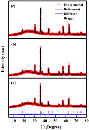 | ||
| Fig. 1 Rietveld refinements fits of the XRD data of the CoFe2O4 samples (a) M700 (b) M800 and (c) M900. | ||
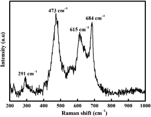
Raman spectroscopy (Fig. 2) was also carried out to confirm the nature of CoFe2O4. Inverse spinel CoFe2O4 shows an A1g symmetry at 684 cm−1 associated with the tetrahedral sub-lattice and octahedral sub-lattice at the peak at 615 cm−1.49,50 The band at 473 cm−1 is attributed to asymmetric bending of Fe (Co)–O.50 Conversely, the Raman band at 291 cm−1 is attributed to the Eg symmetric bending of Fe (Co)–O.51
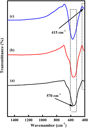
The formation of CoFe2O4 spinel was also supported by the FTIR spectra (Fig. 3). The appearance of two peaks at 570 and 415 cm−1 is closely linked to the stretching vibrations of metal oxide in the octahedral site Co2+–O2− and tetrahedral site Fe3+–O2−, respectively.52,53 These two typical bands can be detected in almost all CoFe2O4 structures.54 However, at relatively higher temperatures, the peaks become sharper and narrower due to lattice distortion minimization and improve the crystallinity.55 This fact is in agreement with XRD.
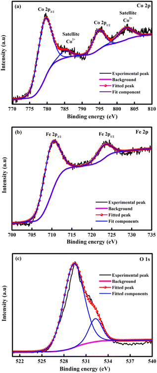
XPS spectroscopy was explained the elemental composition of CoFe2O4 and displays the existence of the Co, Fe and O element as showed in Fig. 4. The deconvoluted spectra of the Co 2p (Fig. 4a) spectra show peaks due to Co 2p3/2 and Co 2p1/2 at binding energy of 779.71 and 794.99 eV respectively.56 In addition, the satellites peaks at 785.38 eV and 802.83 eV indicated the presence of unpaired 3d electron of the high spin Co2+.57,58 In Fig. 4b exposed Fe 2p spectrum and displayed the Fe 2p3/2 and Fe 2p1/2 peaks at 710.54 and 723.58 eV, respectively. These results support the presence of Fe3+ in the inverse spinel CoFe2O4.58 The two peaks at 529.42 and 532.31 eV in a single O 1s fine spectra (Fig. 4c) can be considered as the metal–O bond and consistent with oxygen in the defect, respectively.56,59
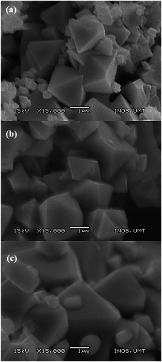
SEM images (Fig. 5) showed a remarkable morphological change as the calcination temperatures increased with average particle size ranging from 1.1 to 3.6 μm. Sample M700 (Fig. 5a) shows an octahedron shape with a particle size of ∼1.1 μm, and sample M800 (Fig. 5b) shows a well-defined octahedral shape, with a faceted surface and size of about ∼2.27 μm. As the temperature increased to 900 °C (M900 (Fig. 5c)), the particle sizes increased to ∼3.64 μm and the morphology became flattened, giving rise to new facets. This condition appears inevitable, primarily because of the interaction between magnetic particles at higher calcination temperatures.60,61
The Brunauer–Emmett–Teller (BET) surface area of the samples was determined using nitrogen adsorption–desorption isotherms measured at 77.3 K (Fig. 6). From the obtained isotherms, all the samples show type IV adsorption isotherms which indicate mesoporous structures. Furthermore, all samples show H3 hysteresis loop which show the characteristic of slit shape features.62,63 The open loop at the isotherm may be caused by slow adsorption at narrow pores which exhibited from slit shape features.63 The specific surface areas of M700, M800, and M900 were found to be 2.6017, 3.6244, and 7.7535 m2 g−1, respectively. In addition, the measured pore volumes of the samples were 0.0020 cm3 g−1 for M700, 0.0032 cm3 g−1 for M800 and 0.0082 cm3 g−1. It is clear that higher calcination temperatures resulted in an increase in the BET surface area due to structural and morphological changes, indicating the emergence of a new facet as shown in the SEM image.64,65
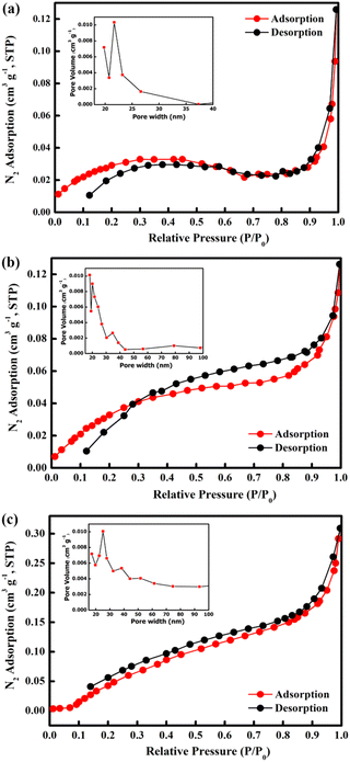 | ||
| Fig. 6 N2 adsorption–desorption isotherms and BJH pore size distribution curves (inset) of CoFe2O4 for (a) M700, (b) M800 and (c) M900. | ||
Further analysis was conducted using TEM images (Fig. 7). The crystalline CoFe2O4 structure demonstrates that the sample M900 possessed dense agglomerates, as illustrated in Fig. 7a. Lattice fringes of CoFe2O4 (Fig. 7b) indicate an interplanar spacing of 0.25 nm belonging to the (311) plane with a cubic phase, which agreed well with the XRD data.
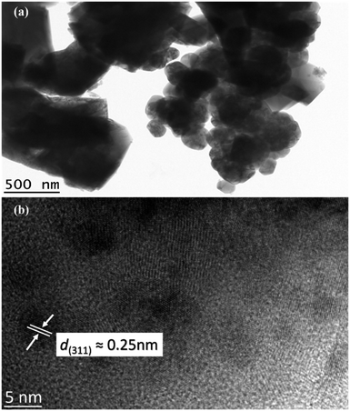 | ||
| Fig. 7 TEM images of M900 at (a) low magnification and (b) high-resolution TEM image of the CoFe2O4. | ||
CV was conducted for all electrodes between 0.01 and 3.0 V at a scan rate of 0.1 mV s−1 (Fig. 8). Throughout the first scan, all electrodes showed a broad-ranging cathodic peak at 0.6 V, consistent with the irreversible emergence of a solid electrolyte interface (SEI); electrolyte deterioration causes a significant irreversible loss of capacity during the first discharge process.33,66 The shift between 0.3 and 0.8 V during the subsequent cycle is attributed to the reduction of Fe3+ and Co2+ to Fe0 and Co0, respectively, and the reversible reaction to form Na2O (eqn (2)):67,68
| CoFe2O4 + 8Na+ + 8e− ↔ Co + 2Fe + 4Na2O | (2) |
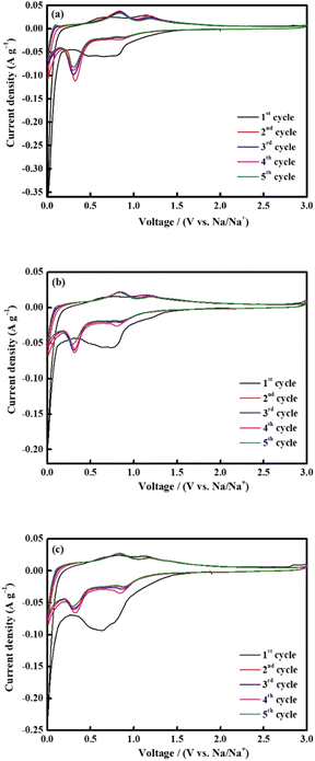 | ||
| Fig. 8 CV measurements of CoFe2O4 (a) M700, (b) M800 and (c) M900 at a scan rate of 0.1 mV s−1 (vs. Na/Na+). | ||
In the anodic process, the oxidation peaks at 0.8 and 1.2 V are attributed to the reformation of CoFe2O4 via the oxidation of Fe0 and Co0 to Fe3+ and Co2+, respectively.69,70 All the CV curves almost overlapped during the subsequent cycle, indicating high reversibility of the electrochemical reaction.33,71 The selected cycles of the charge and discharge profiles for all electrodes at a current density of 0.1 A g−1 is shown in Fig. 9. The charge and discharge plateau for all electrodes is aligned with the CV peaks. The initial capacity of discharge and charge capacities of the electrode are 617 mA h g−1 (M700), 839 mA h g−1 (M800), and 350 mA h g−1 (M900), respectively. Based on these result, M800 electrode deliver higher discharge capacity due to the uniform morphology, suggesting that large contact interface between electrolyte and electrodes, which lead to high irreversible Na+ consumption.72 Contrarily, the large particle size required a longer time for ion transfer into the particles and faces diffusion limitation of Na+ within a single large particle.65,73 All electrodes display irreversible capacity loss owing to the formation of the SEI layer and electrolyte degradation during the first cycle.74,75 However, there is difference for the second discharge curves of the sample M900 and sample M800 and M700 due to considerable loss in specific capacity of the M900 sample.76 This result agreed well with the capacity value of M900 sample which is lower that M800 and M700.
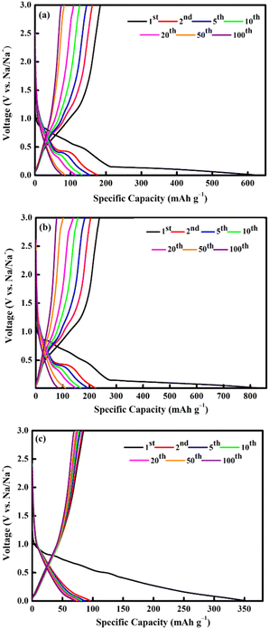 | ||
| Fig. 9 Galvanostatic charge/discharge profiles of CoFe2O4 (a) M700, (b) M800, and (c) M900 at 0.1 A g−1. | ||
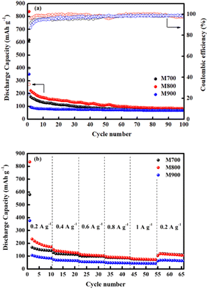
Fig. 10a demonstrates the cycling behaviour of all electrodes at a current density of 0.1 A g−1. At the initial cycle, the M800 electrode exhibits the highest discharge capacity (839 mA h g−1), followed by the M700 (617 mA h g−1) and M900 (350 mA h g−1) electrodes. For the M800 electrode, a preserved discharge capacity of 98 mA h g−1 was calculated after 100 cycles, whereas the discharge capacity for the M700 (76 mA h g−1) and M900 (69 mA h g−1) electrodes. The reversible discharge capacity of the M800 electrode was 224 mA h g−1 after the second cycle and continued to decline throughout the 100 cycles, which was possibly due the activation and stabilisation processes within the electrode.15 In this regard, the observed capacity values of the M800 electrode remain high compared to the other electrodes. Similar trends were also observed for the M700 and M900 electrodes. After 100 cycles, the discharge capacities of the M700 and M900 electrodes were 76 mA h g−1 and 69 mA h g−1, respectively. According to previous reported,77–79 fast capacity fading of materials due to structure collapse and dissolution of materials may occur in electrolyte decomposition. As a result, the improvement in cycling stability of materials is attributed to a delay in structure decay. The specific capacity retained by the M800 electrode after 100 cycles was 88%, compared to 87% and 80% retained by the M700 and M900 electrodes, respectively. Clearly, the initial coulombic efficiencies were 48%, 33% and 24% for the M700, M800 and M900 electrodes, respectively, owing to uncontrolled SEI layer formations. After several cycles, all the electrodes demonstrated high coulombic efficiencies of more than 99% as the SEI layer formation stabilised during cycling.80 The rate capability of all the electrodes was also determined at different current rates, ranging from 0.2 to 1.0 A g−1 (Fig. 10b). The M800 electrode delivered the discharge capacities of 171, 125, 103, 87, 73 and 108 mA h g−1 at the current densities of 0.2, 0.4, 0.6, 0.8, 1.0 and 0.2 A g−1, respectively. Even though the rate returned to 0.2 A g−1, the discharge capacity of M800 electrode could still display the maximum reversible capacity, suggesting stable cycling performance. However, the consecutive cycling performances of the M700 and M900 electrodes were unsatisfactory. After 66 cycles at various charge and discharge rates, the discharge capacity of the M800 electrode at 0.2 A g−1 remained 108 mA h g−1, representing approximately 87% capacity recovery. Hence, the improved cycle and rate performance of the M800 electrode is superior to that of the M700 and M900 electrodes, may be due to the well-defined octahedral shape of M800 delivers sufficient active sites for Na-ion, thus reducing the electron and ion transport pathways.
The improved electrochemical performance of CoFe2O4 (M800) could be assigned to the high crystallinity and homogeneous distribution of particles, leading to a high surface area,81 facilitating electrode–electrolyte interaction and affording increased active sites for electrochemical reactions.82,83 The well-dispersed particles are beneficial for excellent performance because they provide a short transport length and a substantial contact area between the active material and electrolyte.84,85 In this regard, the sample must afford a high surface area for promoting the adsorption and storage of Na-ions.86 M900 presented a large particle size as seen from the SEM image, which in turn severely affect the performance because it is difficult for ions to diffuse into bulk materials. It suggests that increasing the length of diffusion pathways of Na-ions and resulting in unsatisfactory CoFe2O4 behaviour. This method is well recognised for its cost-effective preparation because the products can be produced in large quantities in a short session.87 Scientifically, the salt melts during the preparation method owing to the high rate of ion absorption and high ability to dissolve, which can speed up the rate of the reactions.88 To the best of our knowledge, systematic investigations on the parameters influencing the formation and characteristics of CoFe2O4 during the molten salt method are still lacking. Overall, the discharge capacity of CoFe2O4 discovered in this study is preferable to those previously reported (Table 2). The synthesis of molten salts at low temperatures represents a template and surfactant free, cost-effective, simple and an efficient method for large-scale production. As a result of this study, new insights can be gained for future studies on CoFe2O4 as an anode material for Na-ion batteries.
| Sample | Synthesis method | Current density (A g−1) | Discharge capacity (mA h g−1)/cycle | Reference |
|---|---|---|---|---|
| CoFe2O4 | Hydrothermal | 0.1 | 300/1st cycle | 23 |
| CoFe2O4 | Hydrothermal | 0.05 | 700/1st cycle | 72 |
| CoFe2O4 | Hydrothermal | 0.05 | 500/1st cycle | 34 |
| CoFe2O4 | Annealing metal–organic framework | 0.05 | 573/1st cycle | 33 |
| CoFe2O4 | Molten salt | 0.1 | 839/1st cycle | This work |
4. Conclusions
CoFe2O4 was successfully synthesised using the molten salt method, followed by calcination at 700 °C, 800 °C and 900 °C. The synthesis approach used provides a straightforward and practical way for industrial production. The powder phases, structures, chemical composition and morphology are characterised through XRD, Raman spectroscopy, FTIR, XPS, SEM, BET and TEM. The electrochemical results indicate that the M800 electrode showed excellent performance as an anode material for Na-ion batteries, which could be attributed to the homogeneity, uniform octahedral morphology, and high crystallinity of the material. The M800 electrode revealed a high initial discharge capacity (839 mA h g−1 at 0.1 A g−1) and retained the capacity (98 mA h g−1) after 100 cycles. The capacitive retention was ∼88% after 100 cycles, demonstrating a good rate capability and cycling stability during the insertion and de-insertion of Na-ions. These findings indicate that this strategy may provide an innovative approach to improving the electrochemical behaviour of CoFe2O4 electrodes for use in Na-ion batteries.Author contributions
The manuscript original draft was written by S. U. M. S. U. M., and N. H. I. investigated the molten salt synthesis of disordered spinel CoFe2O4 with improved electrochemical performance for sodium-ion batteries and developed conceptualisation. S. U. M., N. H. I., H. M. Y., F. M. D., S. R. M., and L. N. developed the methodologies. The project was supervised by N. H. I. The manuscript has been reviewed and edited by all contributing authors.Conflicts of interest
The authors declare that they have no known competing financial interest or personal relationships that could have appeared to influence the work reported in this paper.Acknowledgements
The Ministry of Higher Education Malaysia provided funding for this project through the Fundamental Research Grant Scheme (FRGS; FRGS/1/2018/STG07/UMT/02/3). This works was also supported by Penelitian Kerjasama Perguruan Tinggi (Pakerti) Scheme ITS 2022 no. 1053/PKS/ITS/2022. Student scholarship from Yayasan Terengganu is fully acknowledged.References
- M. D. Slater, D. Kim, E. Lee and C. S. Johnson, Adv. Funct. Mater., 2013, 23, 947–958 CrossRef CAS
.
- C. Zhang, X. Wang, Q. Liang, X. Liu, Q. Weng, J. Liu, Y. Yang, Z. Dai, K. Ding, Y. Bando, J. Tang and D. Golberg, Nano Lett., 2016, 16, 2054–2060 CrossRef CAS PubMed
.
- L. Wu, D. Buchholz, C. Vaalma, G. A. Giffin and S. Passerini, ChemElectroChem, 2016, 3, 292–298 CrossRef CAS
.
- Q. Fan, W. Zhang, J. Duan, K. Hong, L. Xue and Y. Huang, Electrochim. Acta, 2015, 174, 970–977 CrossRef CAS
.
- S. W. Zhang, W. Lv, C. Luo, C. H. You, J. Zhang, Z. Z. Pan, F. Y. Kang and Q. H. Yang, Energy Storage Mater., 2016, 3, 18–23 CrossRef
.
- V. Palomares, P. Serras, I. Villaluenga, K. B. Hueso, J. Carretero-González and T. Rojo, Energy Environ. Sci., 2012, 5, 5884–5901 RSC
.
- V. L. Chevrier and G. Ceder, J. Electrochem. Soc., 2011, 158, A1011–A1014 CrossRef CAS
.
- P. Adelhelm, P. Hartmann, C. L. Bender, M. Busche, C. Eufinger and J. Janek, Beilstein J. Nanotechnol., 2015, 6, 1016–1055 CrossRef CAS PubMed
.
- J. Y. Hwang, S. T. Myung and Y. K. Sun, Chem. Soc. Rev., 2017, 46, 3529–3614 RSC
.
- X. Zhang, T. Chen, D. Yan, W. Qin, B. Hu, Z. Sun and L. Pan, Electrochim. Acta, 2015, 180, 616–621 CrossRef CAS
.
- Y. Jiang, M. Hu, D. Zhang, T. Yuan, W. Sun, B. Xu and M. Yan, Nano Energy, 2014, 5, 60–66 CrossRef CAS
.
- X. Deng, Z. Chen and Y. Cao, Mater. Today Chem., 2018, 9, 114–132 CrossRef CAS
.
- F. Wu, C. Zhao, S. Chen, Y. Lu, Y. Hou, Y. S. Hu, J. Maier and Y. Yu, Mater. Today, 2018, 21, 960–973 CrossRef CAS
.
- H. Zhang, I. Hasa and S. Passerini, Adv. Energy Mater., 2018, 8, 1702582–1702621 CrossRef
.
- N. F. M. Yusoff, N. H. Idris, M. F. M. Din, S. R. Majid, N. A. Harun and M. M. Rahman, Sci. Rep., 2020, 10, 9207–9216 CrossRef CAS PubMed
.
- N. F. M. Yusoff, N. H. Idris, M. F. M. Din, S. R. Majid, N. A. Harun and M. M. Rahman, ACS Omega, 2020, 5, 29158–29167 CrossRef PubMed
.
- P. R. Kumar, Y. H. Jung, K. K. Bharathi, C. H. Lim and D. K. Kim, Electrochim. Acta, 2014, 146, 503–510 CrossRef CAS
.
- S. Santangelo, M. Fiore, F. Pantò, S. Stelitano, M. Marelli, P. Frontera, P. Antonucci, G. Longoni and R. Ruffo, Solid State Ionics, 2017, 309, 41–47 CrossRef CAS
.
- C. Han, X. Zhang, X. Xu, Q. Li, Q. He, J. Meng, X. Wang, Z. Liu, P. Wu and L. Mai, Nanoscale, 2018, 10, 12963–12969 RSC
.
- X. Liu, T. Chen, H. Chu, L. Niu, Z. Sun, L. Pan and C. Q. Sun, Electrochim. Acta, 2015, 166, 12–16 CrossRef CAS
.
- Z. Jian, B. Zhao, P. Liu, F. Li, M. Zheng, M. Chen, Y. Shi and H. Zhou, Chem. Commun., 2014, 50, 1215–1217 RSC
.
- L. Yu, L. P. Wang, S. Xi, P. Yang, Y. Du, M. Srinivasan and Z. J. Xu, Chem. Mater., 2015, 27, 5340–5348 CrossRef CAS
.
- Q. He, K. Rui, C. Chen, J. Yang and Z. Wen, ACS Appl. Mater. Interfaces, 2017, 9, 36927–36935 CrossRef CAS
.
- K. Cao, T. Jin, L. Yang and L. Jiao, Mater. Chem. Front., 2017, 1, 2213–2242 RSC
.
- C. Yuan, H. B. Wu, Y. Xie and X. W. Lou, Angew. Chem., Int. Ed., 2014, 53, 1488–1504 CrossRef CAS PubMed
.
- G. Zhang, L. Yu, H. B. Wu, H. E. Hoster and X. W. Lou, Adv. Mater., 2012, 24, 4609–4613 CrossRef CAS PubMed
.
- P. F. Teh, Y. Sharma, S. S. Pramana and M. Srinivasan, J. Mater. Chem., 2011, 21, 14999–15008 RSC
.
- X. Xu, B. Dong, S. Ding, C. Xiao and D. Yu, J. Mater. Chem. A, 2014, 2, 13069–13074 RSC
.
- Y. Chen, J. Zhu, B. Qu, B. Lu and Z. Xu, Nano Energy, 2014, 3, 88–94 CrossRef CAS
.
- J. Li, S. Xiong, Y. Liu, Z. Ju and Y. Qian, ACS Appl. Mater. Interfaces, 2013, 5, 981–988 CrossRef CAS PubMed
.
- R. Alcántara, M. Jaraba, P. Lavela and J. L. Tirado, Chem. Mater., 2002, 14, 2847–2848 CrossRef
.
- Z. Zhang, W. Li, R. Zou, W. Kang, Y. San Chui, M. F. Yuen, C. S. Lee and W. Zhang, J. Mater. Chem. A, 2015, 3, 6990–6997 RSC
.
- X. Zhang, D. Li, G. Zhu, T. Lu and L. Pan, J. Colloid Interface Sci., 2017, 499, 145–150 CrossRef CAS PubMed
.
- J. M. Feng, X. H. Zhong, G. Z. Wang, L. Dong, X. F. Li and D. J. Li, J. Mater. Sci., 2017, 52, 3124–3132 CrossRef CAS
.
- X. H. Li, C. L. Xu, X. H. Han, L. Qiao, T. Wang and F. S. Li, Nanoscale Res. Lett., 2010, 5, 1039–1044 CrossRef CAS PubMed
.
- J. Ding, P. G. McCormick and R. Street, Solid State Commun., 1995, 95, 31–33 CrossRef CAS
.
- H. R. Dehghanpour, Russ. J. Appl. Chem., 2016, 89, 846–849 CrossRef CAS
.
- R. Safi, A. Ghasemi, R. S. Razavi, E. Ghasemi and T. Sodaee, Ceram. Int., 2016, 42, 6375–6382 CrossRef CAS
.
- S. K. Gupta and Y. Mao, J. Phys. Chem. C, 2021, 125, 6508–6533 CrossRef CAS
.
- Y. Mao, T. J. Park, F. Zhang, H. Zhou and S. S. Wong, Small, 2007, 3, 1122–1139 CrossRef CAS PubMed
.
- H. B. Yang, Y. Lin, F. Wang and H. J. Luo, Mater. Technol., 2008, 23, 138–141 CrossRef CAS
.
- P. Kulkarni, R. G. Balkrishna, D. Ghosh, R. S. Rawat, R. Medwal, B. V. R. Chowdari, Z. Karim and M. V. Reddy, Mater. Chem. Phys., 2021, 257, 123747–123757 CrossRef CAS
.
- D. Su, C. Wang, H. Ahn and G. Wang, Phys. Chem. Chem. Phys., 2013, 15, 12543–12550 RSC
.
- N. S. Marzuki, N. U. Taib, M. F. Hassan and N. H. Idris, Electrochim. Acta, 2015, 182, 452–457 CrossRef CAS
.
- S. Kumar, S. Munjal and N. Khare, J. Phys. Chem. Solids, 2017, 105, 86–89 CrossRef CAS
.
- R. Sharma and S. Singhal, Phys. B, 2013, 414, 83–90 CrossRef CAS
.
- P. Vlazan and M. Stoia, Ceram. Int., 2018, 44, 530–536 CrossRef CAS
.
- N. T. T. Loan, N. T. H. Lan, N. T. T. Hang, N. Q. Hai, D. T. T. Anh, V. T. Hau, L. V. Tan and T. V. Tran, Processes, 2019, 7, 885–898 CrossRef CAS
.
- F. Nakagomi, S. W. da Silva, V. K. Garg, A. C. Oliveira, P. C. Morais and A. Franco, J. Solid State Chem., 2009, 182, 2423–2429 CrossRef CAS
.
- V. H. Ojha and K. M. Kant, J. Phys. Chem. Solids, 2021, 148, 109655–109664 CrossRef CAS
.
- V. Bartůněk, D. Sedmidubský, Š. Huber, M. Švecová, P. Ulbrich and O. Jankovský, Materials, 2018, 11, 1241–1252 CrossRef PubMed
.
- Z. Rahimi, H. Sarafraz, G. Alahyarizadeh and A. S. Shirani, J. Radioanal. Nucl. Chem., 2018, 317, 431–442 CrossRef CAS
.
- T. Boobalan, N. Suriyanarayanan and S. Pavithradevi, Mater. Sci. Semicond. Process., 2013, 16, 1695–1700 CrossRef CAS
.
- S. Khizar, N. M. Ahmad, N. Ahmed, S. Manzoor, M. A. Hamayun, N. Naseer, M. K. L. Tenório, N. Lebaz and A. Elaissari, Nanomaterials, 2020, 10, 2182–2197 CrossRef CAS PubMed
.
- L. Kumar, P. Kumar, A. Narayan and M. Kar, Int. Nano Lett., 2013, 3, 8–19 CrossRef
.
- C. Wang, B. Wang, X. Cao, J. Zhao, L. Chen, L. Shan, H. Wang and G. Wu, Composites, Part B, 2021, 205, 108529–108538 CrossRef CAS
.
- Z. Hou, C. Liu, J. Gong, J. Wu, S. Sun, M. Zhang and X. Sun, Coatings, 2022, 12, 1532–1546 CrossRef CAS
.
- T. Ahamad, M. Naushad, M. Ubaidullah and S. Alshehri, Polymers, 2020, 12, 2940–2955 CrossRef CAS PubMed
.
- X. Sun, X. Zhu, X. Yang, J. Sun, Y. Xia and D. Yang, Green Energy Environ., 2017, 2, 160–167 CrossRef
.
- E. R. Kumar, R. Jayaprakash and K. Sanjay, Mater. Sci. Semicond. Process., 2014, 17, 173–177 CrossRef
.
- J. H. Kim, S. T. Myung and Y. K. Sun, Electrochim. Acta, 2004, 49, 219–227 CrossRef CAS
.
- N. A. Idris, H. M. Yusoff, N. H. Idris, N. Badar, K. Elong, S. U. Muhamad, N. F. M. Yusoff and C. P. Wai, Arab. J. Sci. Eng., 2023 DOI:10.1007/s13369-023-08300-y
.
- M. M. Rahman, A. Z. Shafiullah, A. Pal, M. A. Islam, I. Jahan and B. B. Saha, Energies, 2021, 14, 7478–7497 CrossRef CAS
.
- O. Amadine, Y. Essamlali, A. Fihri, M. Larzek and M. Zahouily, RSC Adv., 2017, 7, 12586–12597 RSC
.
- N. D. Rosedhi, N. H. Idris, M. M. Rahman, M. F. M. Din and J. Wang, Electrochim. Acta, 2016, 206, 374–380 CrossRef CAS
.
- H. Guo, T. Li, W. Chen, L. Liu, X. Yang, Y. Wang and Y. Guo, Nanoscale, 2014, 6, 15168–15174 RSC
.
- H. Xia, D. Zhu, Y. Fu and X. Wang, Electrochim. Acta, 2012, 83, 166–174 CrossRef CAS
.
- H. Yu, H. Fan, X. Wu, H. Wang, Z. Luo, H. Tan, B. Yadian, Y. Huang and Q. Yan, Energy Storage Mater., 2016, 4, 145–153 CrossRef
.
- Q. Cao, Z. Liu and R. Che, New J. Chem., 2014, 38, 3193–3198 RSC
.
- M. Zhao, J. Xiong, Y. Yang and J. Zhao, ChemElectroChem, 2019, 6, 3468–3477 CrossRef CAS
.
- T. Wang, K. Zhang, M. Park, V. W. h. Lau, H. Wang, J. Zhang, J. Zhang, R. Zhao, Y. Yamauchi and Y. M. Kang, ACS Nano, 2020, 14, 4352–4365 CrossRef CAS PubMed
.
- D. Zhou, L. P. Xue and N. Wang, ChemElectroChem, 2019, 6, 1552–1557 CrossRef CAS
.
- T. Drezen, N. H. Kwon, P. Bowen, I. Teerlinck, M. Isono and I. Exnar, J. Power Sources, 2007, 174, 949–953 CrossRef CAS
.
- Y. Zhou, W. Sun, X. Rui, Y. Zhou, W. J. Ng, Q. Yan and E. Fong, Nano Energy, 2016, 21, 71–79 CrossRef CAS
.
- J. Chen, Q. Ru, Y. Mo, S. Hu and X. Hou, Phys. Chem. Chem. Phys., 2016, 18, 18949–18957 RSC
.
- D. P. Dutta, D. D. Pathak, S. Abraham and B. R. Ravuri, RSC Adv., 2022, 12, 12383–12395 RSC
.
- P. Pang, Z. Wang, X. Tan, Y. Deng, J. Nan, Z. Xing and H. Li, Electrochim. Acta, 2019, 327, 135018–135026 CrossRef CAS
.
- P. Pang, Z. Wang, Y. Deng, J. Nan, Z. Xing and H. Li, ACS Appl. Mater. Interfaces, 2020, 12, 27339–27349 CrossRef CAS PubMed
.
- P. Pang, X. Tan, Z. Wang, Z. Cai, J. Nan, Z. Xing and H. Li, Electrochim. Acta, 2021, 365, 137380–137389 CrossRef CAS
.
- N. F. M. Yusoff, N. H. Idris, M. F. M. Din, S. R. Majid, N. A. Harun and L. Noerochim, Nanomaterials, 2023, 13, 732–748 CrossRef CAS PubMed
.
- Y. Zhang, Y. Lu, S. Feng, D. Liu, Z. Ma and S. Wang, J. Mater. Chem. A, 2017, 5, 22512–22518 RSC
.
- J. Li, D. Yan, S. Hou, T. Lu, Y. Yao, D. H. C. Chua and L. Pan, Chem. Eng. J., 2018, 335, 579–589 CrossRef CAS
.
- J. Guo, Q. Liu, C. Wang and M. R. Zachariah, Adv. Funct. Mater., 2012, 22, 803–811 CrossRef CAS
.
- C. Jiang, E. Hosono and H. Zhou, Nano Today, 2006, 1, 28–33 CrossRef
.
- P. G. Bruce, B. Scrosati and J. M. Tarascon, Angew. Chem., Int. Ed., 2008, 47, 2930–2946 CrossRef CAS PubMed
.
- Y. Wang, J. Bian, W. Ren and C. Cheng, Mater. Res. Bull., 2021, 139, 111248–111255 CrossRef CAS
.
- E. Lancry, E. Levi, A. Mitelman, S. Malovany and D. Aurbach, J. Solid State Chem., 2006, 179, 1879–1882 CrossRef CAS
.
- W. Tang, X. Yang, Z. Liu, S. Kasaishi and K. Ooi, J. Mater. Chem., 2002, 12, 2991–2997 RSC
.
| This journal is © The Royal Society of Chemistry 2023 |

