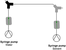
 Open Access Article
From monomer to micelle: a facile approach to the multi-step synthesis of block copolymers via inline purification†
Pieter-Jan
Voorter
ab,
Gayathri
Dev
ac,
Axel-Laurenz
Buckinx
ad,
Jinhuo
Dai
d,
Priya
Subramanian
d,
Anil
Kumar
 c,
Neil R.
Cameron
 be and
Tanja
Junkers
 *a
*a
aPolymer Reaction Design Group, School of Chemistry, Monash University, 19 Rainforest Walk, Building 23, Clayton, VIC 3800, Australia. E-mail: tanja.junkers@monash.edu
bDepartment of Materials Science and Engineering, Monash University, 14 Alliance Lane, Clayton, Victoria 3800, Australia
cDepartment of Chemistry, Indian Institute of Technology Bombay, Mumbai 400076, India
dDulux Australia, 1956 Dandenong Road, Clayton, VIC 3168, Australia
eSchool of Engineering, Warwick University, Coventry CV4 7AL, UK
First published on 6th June 2023
Abstract
A one-pass continuous flow strategy to form block copolymer nanoaggregates directly from monomers is presented. A key development towards such a sophisticated continuous flow setup is a significant improvement in continuous flow dialysis. Often impurities or solvent residues from polymerizations must be removed before block extensions or nanoaggregate formation can be carried out, typically disrupting the workflow. Hence, inline purification systems are required for fully continuous operation and eventual high throughput operation. An inline dialysis purification system is developed and exemplified for amphiphilic block copolymer synthesis from thermal and photoiniferter reversible addition fragmentation chain transfer (RAFT) polymerization. The inline dialysis system is found to be significantly faster than conventional batch dialysis and the kinetics are found to be very predictable with a diffusion velocity coefficient of 4.1 × 10⁻⁴ s−1. This is at least 4–5 times faster than conventional dialysis. Moreover, the newly developed setup uses only 57 mL of solvent for purification per gram of polymer, again reducing the required amount by almost an order of magnitude compared to conventional methods. Methyl methacrylate (MMA) or butyl acrylate (BA) was polymerized in a traditional flow reactor as the first block via RAFT polymerization, followed by a ‘dialysis loop’, which contains a custom-built inline dialysis device. Clearance of residual monomers is monitored via in-line NMR. The purified reaction mixture can then be chain extended in a second reactor stage to obtain block copolymers using poly(ethylene glycol) methyl ether acrylate (PEGMEA) as the second monomer. In the last step, nano-objects are created, again from flow processes. The process is highly tuneable, showing for the chosen model system a variation in nanoaggregate size from 34 nm to 188 nm.
Introduction
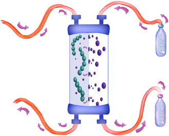
Modern polymer synthesis is under pressure to create polymers with new specific properties at an increasing pace.1 Block copolymers have a wide range of potential applications due to their versatility in composition and microstructure. In this respect, continuous high-throughput manufacturing of functional block copolymers and nanoaggregates made thereof is highly desirable. Living polymerization techniques such as nitroxide mediated polymerization (NMP),2,3 atom transfer radical polymerization (ATRP)4,5 and reversible addition–fragmentation chain transfer (RAFT)6–8 polymerization are widely employed for the synthesis of multiblock polymers. Specifically, RAFT polymerization is the technique that gives access to the broadest range of functionalities and is, in this context, often the method of choice for synthesizing multiblock copolymers. Multiblock copolymerization via RAFT is very efficient if performed under the right conditions. High chain end fidelity and efficient re-initiation of macroRAFT species are crucial for producing well-defined block copolymers.6,8–10Flow chemistry is known to improve control over polymerization and is often combined with RAFT polymerization. Moreover, flow chemistry also simplifies upscaling due to its efficient heat transfer properties, causing a uniform temperature distribution throughout the reactor.11–13 As an example, Baeten et al. synthesized tetra-block copolymers via RAFT polymerization in flow in different reactors connected in series.14 After extensive kinetic studies, they were able to assume complete conversion of the monomer and complete initiator usage after every block formation, ensuring good block copolymer synthesis. This approach was, however, limited to monomers with fast propagation rates to keep reactor residence reasonably low and suitable for flow chemistry.15 If a residual monomer was still present, statistical copolymers rather than block copolymers would be obtained. This is a significant drawback in the design because not all monomers can be used in this fast and facile method to create block copolymers. Gody et al. proposed the use of a looped flow RAFT polymerization setup to tackle this problem. Their setup allowed the looping of the reaction mixture through a heated reactor until complete conversion was reached, making the volume of the reactor independent of the reaction time. When full conversion had been reached, a new monomer and initiator were introduced to the reaction mixture.16 Thus, this allowed the reactivity issue to be mitigated, yet required constant monitoring of reactions and was limited with respect to scaling the reaction. A different approach would in contrast be to use an inline purification step between block formations (see Fig. 1). This gives the option to use the same reactor and setup also for less reactive monomers and to eliminate any initiator fragments or other side products that may be present in the reaction mixture at the end of the polymerization.17,18 Instead of avoiding residual monomer, monomer would be removed from the mixture, not unlike to what is standard in classical batch synthesis. However, polymer purification in flow is a less explored field compared to synthesis and characterisation and has to date not been realized.19 Removing the requirement of either offline isolation of polymers or the need to obtain practically complete conversion in flow to avoid residual monomers will enable the use of many other polymers in flow block copolymer synthesis, as less reactive monomers could be used without problems, such as methacrylates of styrene.
In batch, the purification of a particular mixture where a miscible solvent or small molecule – such as a monomer – has to be removed, is typically performed via precipitation or in cases where the polymer is not a solid or is difficult to precipitate via dialysis. With dialysis, a cellulose membrane is typically used with a pore size small enough (molecular weight cut-off in this project is ∼3500 Da) that will not let the species of interest (e.g. polymers) diffuse across the membrane but allows small molecules and solvents to pass.20,21 The smaller molecules will pass through the membrane via osmosis until an equilibrium in concentration is reached on both sides of the membrane. This concentration gradient across the membrane is the driving force behind diffusion.22–25 Batch dialysis is often a time-consuming process taking more than 24 hours and is typically limited to rather small amounts of product since the polymer needs to be filled into small dialysis bags. It is conventionally not scalable. The solvent must be renewed several times to keep the concentration gradient across the membrane high enough to promote the diffusion and removal of all the solvents or smaller molecules. In flow, it has been shown that the concentration gradient can be kept high at all times, accelerating the dialysis. Verstraete et al. demonstrated this when purifying block copolymer nanoaggregates from residual organic solvent in continuous flow.22 In principle, such an inline purification system can be directly coupled to any continuous flow system, including multiblock synthesis. This eliminates the limitation of using highly reactive monomers in a flow process. Schuett et al. were the first to automate batch dialysis using simple robotics for the multi-step synthesis of block copolymers.26 In their approach, a traditional batch dialysis method is used and the dialysis is followed via NMR to track the monomer removal over time. This setup was later updated with an extra pump that gives circulation to the solvent outside of the dialysis bag to promote a higher concentration gradient and therefore faster dialysis.27 Terzioğlu et al. demonstrated, shortly after, the strength of the dialysis method in an automated setup for high throughput screening for synthesising a polymer library using sophisticated parallel synthesis equipment.28
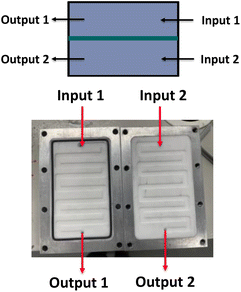
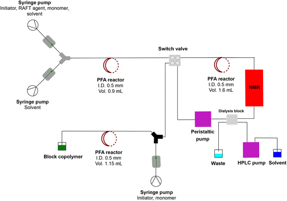
For this work, a simple, comparatively cheap and reusable setup was built to produce multiblock copolymers via RAFT polymerization in a continuous flow process without the disturbing interference of residual monomers affecting the block copolymer fidelity. This approach solves the issues previously encountered by Baeten et al.,14 yet is much faster than any other described technique to date. Reusability is achieved by allowing dialysis membranes to be reused for various runs. Acrylate or methacrylate monomers are polymerized in a conventional flow reactor. As a major improvement, the block copolymer formation is entirely independent of the obtained conversion of the monomer in the first block polymerization. The macroRAFT agent is purified via inline dialysis using a custom designed flow dialysis block (see Fig. 2). The setup makes it possible to synthesise different block copolymers in a single day as dialysis is significantly accelerated. It further allows nanostructures such as micelles to be created in a similar fashion, also continuously, allowing us to quickly change the composition of a block copolymer and to study – in principle – compositional influences on the nanoaggregate size (see Fig. 3).29 In principle, synthesis from the monomer stage to nanoparticles can be achieved in a single setup without intermediate isolation or other interruption. This is unprecedented to date and can also be applied to monomers such as methacrylates, which so far have been difficult to use in block copolymers in flow synthesis. Also, morphological studies of nanoaggregates are possible in principle, yet this was not at the centre of this investigation. It should hereby be noted that the term micelle is often loosely used in the literature, and nanoaggregates, even if spherical and small in size might not be micelles in the stricter sense of the word.
Results and discussion
Design of the dialysis unit
A simple dialysis system was built, as depicted in Fig. 2. The materials were chosen because of their durability and compatibility with most organic solvents. A dialysis block frame was constructed out of 6061 aluminium; block fittings are stainless steel, shallow flow channels are made out of PTFE, and an O-ring seal is made out of 90 × 1.5 mm nitrile 70 duro. The two flow channels are separated by a regenerated cellulose membrane with a pore size of 3.5 kDa (SpectraPor). The block has two outlets and two inlets that fit 1/4-28 flat-bottom (IDEX XP-230) (schematic drawing of the dialysis block is in the ESI†). One inlet is for the polymer reaction mixture, and the other is for the solvent. Both are continuously flowing, which enables a fast exchange of the polymer reaction mixture with the continuously replenished solvent. Compared to our previous design, the unit employed in this work features a larger surface area and is generally larger, to allow for a faster exchange of molecules over the membrane and in order to maximize the amount of material that can be removed in a single pass through the device.Synthesis of macroRAFT
Poly(butyl acrylate) (PBA) and poly(methyl methacrylate) (PMMA) are commonly used polymers in the polymer industry. For the polymerization of butyl acrylate AIBN was used as the initiator at 90 °C to ensure high monomer conversions and n-butanol was used as the solvent (see the ESI†) in accordance to our previous work (see Scheme 1). H-bonding in n-butanol is known to cause a significant reduction of midchain radicals formed during the polymerization.30 This intramolecular chain transfer can cause a reduced reaction rate and the formation of branch points on the polymer. This can potentially influence the self-assembly of the nanostructures later on in the setup and should be avoided as much as possible. Homogeneous polymerization conditions were still obtained at 4 molar solution for butyl acrylate. Despite the high-concentration solutions, no viscosity problems were noted in the flow reactors that potentially could alter the polymerization or dialysis processes. For the homopolymerization, conversions are followed via inline NMR. Kinetic conversion studies have been reported elsewhere.31 High conversions were obtained as expected after 16 minutes, yet small amounts of monomer were typically still present with up to 15% of the starting monomer concentration.MMA was polymerized via photoiniferter polymerization in continuous flow at 90 °C (see Scheme 1). In photoiniferter polymerization the RAFT agent or RAFT polymers themselves can act as a radical source under UV and visible light irradiation.32 A blue light source is used to initiate the polymerization controlled by a trithiocarbonate via the interplay of the iniferter mechanism and the classical thermal RAFT polymerization scheme. This combination of light initiation and thermal activation of propagation means that after 20 minutes high conversions are obtained for methacrylates. Typically, batch reaction times of 8–24 hours are required for high conversions for this monomer class due to the slower propagation of the methacrylate macroradicals. With our high temperature photoiniferter polymerization, monomer conversion was found to be typically around 90%.
Dialysis loop
After synthesis of the homopolymer was satisfactorily established, residual monomers and other small molecules, such as the left-over initiator, needed to be removed. As mentioned before, for block copolymers the residual monomer is detrimental to a successful block extension. Any left-over monomer will mix with the newly introduced monomer, leading to a statistical copolymer rather than a pure block. A residual initiator will influence the kinetics of the block extension, possibly causing other issues. Minimal amounts of residual monomer may be tolerable, yet the bulk of it is mandatory to be removed. The principle of the dialysis loop is straightforward. First, the continuous flow loop is filled with the freshly synthesized homopolymer and the residual monomer mixture from the first reaction stage. Then, the loop is closed, and the flow rate in the loop is set to 0.2 mL min−1, as is the flow rate of the solvent used for purification. This flow rate was determined to be optimal for the employed dialysis system. The complete setup of the synthesis/dialysis platform is shown in Fig. 3.Via inline NMR spectroscopy, we followed the removal of the monomer. The integrals of the vinyl peaks of the monomer are observed in comparison to the backbone peaks of the polymer. As a result of this, dialysis progress is easily surveyed. In Fig. 4, the dialysis kinetics can be seen for the different macroRAFT species under investigation (we synthesized polymers of different degrees of polymerization, DP, to test for chain length influences of the dialysis). A waved clearance pattern was observed in all cases. This phenomenon is caused by the flow rate changing upon closing the dialysis loop. Since we performed dialysis immediately after synthesis, no flow stabilization time was added; otherwise the wave pattern would not be observed. An inline NMR spectrometer was placed in front of the dialysis block. This means that data are collected first before any dialysis has taken place, allowing the progress of the dialysis to be estimated correctly. If it were placed after the dialysis block, the wavy pattern would already be less pronounced. The dialysis loop is 5 mL in size, out of which the dialysis block takes a volume of 3 mL. As can be seen, all macroRAFT species show a similar clearance kinetics profile. The results are well reproducible, allowing for a deeper analysis of the clearance rates.
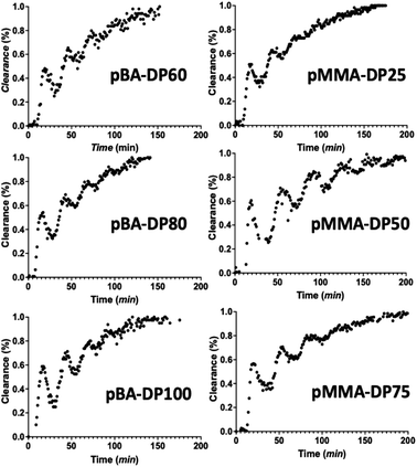 | ||
| Fig. 4 Clearance kinetics by dialysis of PBA and PMMA monitored inline via low field NMR spectroscopy. | ||
Kinetics of the dialysis
The kinetics of dialysis has been well-studied by Schuett et al.27,33 Their work describes diffusion kinetics of the traditional dialysis method in batch in which the outer solvent is refreshed with a specific flow rate. A first analysis is performed via Fick's law which describes the temporal and spatial evolution of the monomer concentration in a static experiment. They altered the calculations with a more advanced formula for explaining how the concentrations in the dialysis bag (cI) and outside the dialysis bag (cO) evolve in the inner sample volume (VI) and the outer purification volume (VO): | (1) |
 | (2) |
The diffusion velocity coefficient is described using the coefficient k, whereas F describes an external flow replacing solvent in the outer volume. In our system, the outer purification volume is continuously refreshed. The monomer concentration in the purification volume is, therefore, always practically zero. This means that every time the sample volume passes, the only limiting factor in the rate of dialysis is the concentration of the monomer in the sample volume. The equation can therefore be largely simplified to:
 | (3) |
Results for the dialysis velocity coefficient k are given in Table 1. The difference in monomer concentrations with every pass through the NMR spectrometer is monitored. The volume within the dialysis block is 3 mL, with a flow rate of 0.2 mL min−1, which means that the effective time spent in dialysis per loop is only 900 seconds. The dialysis velocity coefficient k can be calculated from the initial concentration and the clearance of the monomer per loop. It was found that k is on average 4.1 × 10⁻⁴ s−1, irrespective of the monomer to be removed. As expected from eqn (3), the dialysis velocity is also independent of the concentration of the remaining monomer. Overall, when compared to conventional batch dialysis, the k coefficients in flow are 4–5 times higher, showing the high efficiency of the flow method.
| Sample | k (s−1) | c (polymer) (mol L−1) | c initial (monomer) (mol L−1) |
|---|---|---|---|
| pBA–DP60 | 4.22 × 10⁻⁴ | 3.48 | 0.52 |
| pBA–DP80 | 4.11 × 10⁻⁴ | 3.38 | 0.72 |
| pBA–DP100 | 3.89 × 10⁻⁴ | 3.6 | 0.4 |
| pMMA–DP40 | 4.00 × 10⁻⁴ | 2.67 | 0.33 |
| pMMA–DP45 | 4.22 × 10⁻⁴ | 2.7 | 0.3 |
| pMMA–DP65 | 4.33 × 10⁻⁴ | 2.67 | 0.33 |
The observed larger k is due to the design of the dialysis block. The very shallow flow channels increase the surface-volume ratio across the membrane, which increases the chance of the monomer being in contact with the membrane and therefore the clearance rate of the dialysis. Moreover, the zigzag structure of the channels creates turbulence within the solvents which increases the mixing of monomers in both phases. If a monomer crosses the membrane, it is immediately removed in the flow with the solvent phase always maintaining the highest concentration gradient. These adaptations mean that the purification process can be completed in significantly less time, making multi-reaction processes possible in hours. It should be thereby noted that no difference is seen if the purification solvent is pumped in crossflow, or in parallel to the polymer solution, underpinning that the concentration gradient is indeed always at its maximum.
With knowledge of the dialysis velocity coefficient, the dialysis becomes predictable and the inline NMR that we employed is in principle not required to monitor the progress of monomer removal. This is much more difficult to achieve for traditional batch reactions due to variation in setups and less control over concentration gradients. To exemplify the high predictability, we compared the clearance of the monomer as obtained per pass through the NMR with predictions made with the average k determined above. Fig. 5 nicely shows the close match that is obtained between experiment (markers) and prediction (full line) as an example for the clearance of the monomer from the pBA–DP60 sample. All clearance curves look fairly similar to each other as can be expected from the close match of the k values as indicated in Table 1.
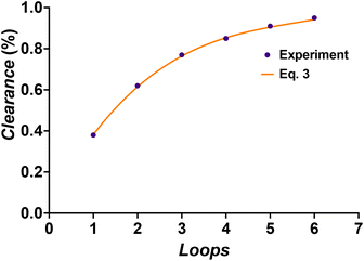 | ||
| Fig. 5 Comparison of the predicted clearance of the monomer viaeqn (3) for pBA–DP60 and the measured progress of clearance via inline NMR. | ||
Overall, one can see that the purification of the monomer is finished within six loops. With a flow rate of 0.2 mL min−1, every loop takes 25 minutes. Purification is hence finished after 2.5 hours. It should be noted that our previous experiments had already demonstrated that lowering the flow rate allowed for faster clearance of contaminants per loop, yet at the same time left the overall dialysis time unchanged as loops took longer. While 2.5 h may seem long at first glance, this is significantly shorter than any other method where purification often takes a day or longer. It is possible to increase the volume of the dialysis loop if larger quantities of purified polymers are needed, but this will decrease the ratio of contact time with the membrane over the total time of the dialysis and therefore make total purification slower. However, it is possible without problem to place several dialysis blocks in series, as is for example also performed for other liquid–liquid extractions in continuous flow. Hypothetically, if we had used 5 additional dialysis units in our setup, we could have purified all monomers from the first block in a single pass, allowing for completely continuous operation, while bringing the dialysis time even more down since dead volume from passing the NMR could be reduced. Furthermore, even though we used inline NMR to monitor the monomer removal for this work, the steady clearance kinetics that we observed allow dialysis to be performed without any online monitoring reliably.
Green chemistry considerations
Other important factors in evaluating continuous flow dialysis are green chemistry metrics. Dialysis is quite wasteful as large quantities of purification solvent are used and eventually end up as waste. In fact, the vast majority of waste produced in the process stems from dialysis typically, with amounts far exceeding the amount of solvent required in the synthesis of polymers. In batch, large volume of purification solvent is typically used to keep the outer concentration as low as possible to maintain a concentration gradient. This often consumes litres of solvent for minute amounts of materials being purified. With flow dialysis, the amount of solvent used is much lower, even though we operate the setup continuously. With the flow rate of 0.2 mL min−1 that we used herein, only about 50 mL purification solvent is consumed for a full purification. For the homopolymers discussed herein, this would come down to around 57 mL solvent needed per gram of monomer that is purified. The traditional dialysis method, independent of the rate of purification, would need a minimum of 250 mL solvent per gram of purified monomer.27 Hence, the e-factor of the dialysis process is roughly better by a factor of 5 for our method and hence displays a major improvement with respect to the principles of green chemistry.Synthesis of block copolymers
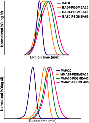
With the completion of the dialysis characterization, we continued to use the setup as depicted in Fig. 3 to demonstrate block copolymer formation. First, the polymer is synthesized in the first reactor stage and the dialysis loop is filled. Once the loop is filled, the polymerization of the first block is halted. Once the 6 loops in the dialysis have been passed, the loop is re-opened. Via a Y micromixer a fresh monomer and an initiator (polyethylene glycol methyl ether acrylate, PEGMEA) are introduced, and block extension of the macroRAFT is continued in the third reactor stage. Different degrees of polymerization can be targeted for the second block with the same reaction solution by changing the flow rate of the syringe pump containing the monomer-initiator solution. The residence time of the second reactor is 30 minutes. By altering the macroRAFT stream and the monomer stream in different ratios, the desired chain extension can be created while having the same residence time for the reactor. As can be seen from Fig. 6 all chain extensions were successful for the BA and the MMA polymers. More examples of chain extensions can be found in the ESI.† In all cases, intermediate dispersities are observed after block extension (see Table 2). We hence tested if the reaction was limited by a loss of end group fidelity during the dialysis, yet via electrospray ionization mass spectrometry (see the ESI†) it was confirmed that end group fidelity was high and that no change occurred during flow dialysis. Furthermore, block extension in batch showed similar dispersities, demonstrating that the dispersities are due to the inherent chemistry of the chosen block copolymer system or caused by imperfect separation of the amphiphilic polymers on the SEC system used. It should be noted that PEGMEA was chosen as the model monomer, to study a challenging block extension towards amphiphilic BCP. PEGMEA itself has a molecular weight distribution, which contributes to the broader dispersities of the BCP.| Sample | Conversion (%) | M n (g mol−1) | Đ |
|---|---|---|---|
| pBA–DP60–pPEGMEA–DP25 | 16 | 8800 | 1.48 |
| pBA–DP60–pPEGMEA–DP45 | 17 | 10![[thin space (1/6-em)]](https://www.rsc.org/images/entities/char_2009.gif) 560 560 |
1.56 |
| pBA–DP60–pPEGMEA–DP65 | 16 | 11![[thin space (1/6-em)]](https://www.rsc.org/images/entities/char_2009.gif) 880 880 |
1.64 |
| pMMA–DP25–pPEGMEA–DP25 | 78 | 9750 | 1.27 |
| pMMA–DP25–pPEGMEA–DP45 | 71 | 14![[thin space (1/6-em)]](https://www.rsc.org/images/entities/char_2009.gif) 000 000 |
1.45 |
| pMMA–DP25–pPEGMEA–DP65 | 65 | 18![[thin space (1/6-em)]](https://www.rsc.org/images/entities/char_2009.gif) 560 560 |
1.76 |
Micelle preparation
As a last step, we tested if the same principle could be applied to BCP self-assembly. The synthesized amphiphilic BCPs are able to form nanoaggregates of various structures, such as spherical micelles, vesicles, or rods.1 Depending on the application, shape and size can be significant. Properties such as chain length and amphiphilicity play a vital role in the self-assembling properties. Availability of an automatable flow process would enable high throughput studies into nanoaggregate formation. The protocol for making nanoaggregates in flow was taken from the literature and adapted to fit our setup.29 For this aim, we extended the setup depicted in Fig. 3 with an attachment, as shown in Fig. 7via a union assembly (P-702) at the output of the block extension reactor. The first syringe pump in this extension provides dilution of the BCP mixture by a factor of ten. Then, a Y-micromixer is used to mix the diluted polymer mixture with water, causing rapid nanoaggregate formation. Due to the amphiphilic character of the BCP different nanostructures will be obtained.22 It should be noted that no monomer removal is, strictly speaking, required at this point in time, even though its presence can have an effect on the obtained nanostructure.The control over the polymerization of the block copolymers means that there is control over the composition of the BCPs and in consequence also the size of the nanoaggregates. This complete design offers the opportunity to not only prepare nanoaggregates on a large scale in a rapid fashion but also gives a platform for screening different block lengths and studying their nanostructure-counterparts. Table 3 provides an overview of the DLS results. As can be seen, an impressive variability is observed in the particle sizes from 34 nm to 188 nm, even if PDIs are in the intermediate regime. This result underpins the general idea that flow dialysis can bridge the gap in BCP flow synthesis, finally reaching the goal of producing micelles in series starting directly from the monomer. As such, the presented setup and its attachment for micelle formation provide the foundation for much more detailed studies into effects of BCP nature, composition and length on nanoaggregate formation.
| Sample | pPEGMEA25 | pPEGMEA45 | pPEGMEA65 | |||
|---|---|---|---|---|---|---|
| Size/nm | PDI | Size/nm | PDI | Size/nm | PDI | |
| pBA–DP60 | 34 | 0.261 | 70 | 0.202 | 136 | 0.261 |
| pBA–DP80 | 49 | 0.193 | 78 | 0.278 | 144 | 0.273 |
| pBA–DP100 | 90 | 0.21 | 154 | 0.263 | 188 | 0.237 |
Conclusions
A new flow dialysis device is investigated via inline NMR spectroscopy. Butyl acrylate and methyl methacrylate were polymerized via RAFT polymerization using thermal and photoiniferter polymerization. The unreacted monomer was removed via a distinctly faster inline purification method than the conventional batch method with a very low amount of solvent use. A kinetic study was performed on the rate of purification. It was found that the dialysis is dependent in the first order on the concentration of monomer in the reaction mixture. Due to the continuous replenishment of fresh solvent, which provides a constant optimal concentration gradient, no other dependency is given. Purification is perfectly predictable and fast. After purification, chain-extension of the homopolymers was performed using poly(ethylene glycol) methyl ether acrylate to create well-defined block copolymers. These block copolymers are then transformed into nanoaggregates within the same setup making the monomer to nanoaggregate process feasible within one single pass of the setup. We believe that this methodology allows research on block copolymer self-assembly to be sped up significantly. For the first time, fully automated high-throughput block copolymer synthesis and purification from continuous flow are available. Efficiency of synthesis and purification is maximized and can be applied to monomers of very different reactivity. Furthermore, the presented purification methodology is very favourable from a green chemistry perspective, saving significant amounts of solvent waste. The purification alone is probably already a highly favourable process for many research labs working on block copolymers in general. While the setup used here is rather complex, the purification itself is simple to perform and does not, after initial characterization, require any sophisticated machinery. We believe that such a system will become widespread and also be used by laboratories that typically don't perform flow synthesis. With just two syringe pumps and a flow dialysis block, purification can be performed in any lab with high precision, predictability and reproducibility. As such, flow dialysis combines all the advantages that continuous flow operation generally provides.Data availability
Data is available in the ESI,† or available on request from the authors.Author contributions
Pieter-Jan Voorter: conceptualization, methodology, visualization, investigation, validation, writing – original draft. Gayathri Dev: investigation. Axel-Laurenz Buckinx: conceptualization. Jinhuo Dai: supervision. Priya Subramanian: supervision Anil Kumar: supervision. Neil R. Cameron: supervision, writing – reviewing and editing. Tanja Junkers: conceptualization, writing – reviewing and editing, supervision.Conflicts of interest
There are no conflicts to declare.Acknowledgements
The Australian Research Council (ARC) is acknowledged for funding via project DP190103309. The authors further wish to thank China Rose Lancaster for helping with the table of contents artwork, Iyomali Abeysekera for measuring the ESI and Jono Wilson for fabricating the dialysis block.Notes and references
- H. Feng, X. Lu, W. Wang, N.-G. Kang and J. W. Mays, Polymers, 2017, 9, 494 CrossRef PubMed.
- C. J. Hawker, A. W. Bosman and E. Harth, Chem. Rev., 2001, 101, 3661–3688 CrossRef CAS.
- J. Nicolas, Y. Guillaneuf, C. Lefay, D. Bertin, D. Gigmes and B. Charleux, Prog. Polym. Sci., 2013, 38, 63–235 CrossRef CAS.
- K. Matyjaszewski, Macromolecules, 2012, 45, 4015–4039 CrossRef CAS.
- T. Noda, A. J. Grice, M. E. Levere and D. M. Haddleton, Eur. Polym. J., 2007, 43, 2321–2330 CrossRef CAS.
- G. Gody, T. Maschmeyer, P. B. Zetterlund and S. Perrier, Macromolecules, 2014, 47, 3451–3460 CrossRef CAS.
- J. J. Haven, C. Guerrero-Sanchez, D. J. Keddie, G. Moad, S. H. Thang and U. S. Schubert, Polym. Chem., 2014, 5, 5236–5246 RSC.
- G. Gody, R. Barbey, M. Danial and S. Perrier, Polym. Chem., 2015, 6, 1502–1511 RSC.
- G. Gody, T. Maschmeyer, P. B. Zetterlund and S. Perrier, Nat. Commun., 2013, 4, 2505 CrossRef PubMed.
- H. Gemici, T. M. Legge, M. Whittaker, M. J. Monteiro and S. Perrier, J. Polym. Sci., Part A: Polym. Chem., 2007, 45, 2334–2340 CrossRef CAS.
- K. Jähnisch, V. Hessel, H. Löwe and M. Baerns, Angew. Chem., Int. Ed. Engl., 2004, 43, 406–446 CrossRef PubMed.
- D. Wilms, J. Klos and H. Frey, Macromol. Chem. Phys., 2008, 209, 343–356 CrossRef CAS.
- K. S. Elvira, X. C. i Solvas, R. C. Wootton and A. J. deMello, Nat. Chem., 2013, 5, 905–915 CrossRef CAS PubMed.
- E. Baeten, J. J. Haven and T. Junkers, Polym. Chem., 2017, 8, 3815–3824 RSC.
- T. Schuett, J. Kimmig, S. Zechel and U. S. Schubert, Polymers, 2020, 12, 2095 CrossRef CAS.
- A. Kuroki, I. Martinez-Botella, C. H. Hornung, L. Martin, E. G. L. Williams, K. E. S. Locock, M. Hartlieb and S. Perrier, Polym. Chem., 2017, 8, 3249–3254 RSC.
- N. Weeranoppanant and A. Adamo, ACS Med. Chem. Lett., 2020, 11, 9–15 CrossRef CAS PubMed.
- J. García-Lacuna and M. Baumann, Beilstein J. Org. Chem., 2022, 18, 1720–1740 CrossRef.
- R. Upadhya, M. J. Kanagala and A. J. Gormley, Macromol. Rapid Commun., 2019, 40, e1900528 CrossRef PubMed.
- P. Gunness, B. M. Flanagan, K. Shelat, R. G. Gilbert and M. J. Gidley, Food Chem., 2012, 134, 2007–2013 CrossRef CAS PubMed.
- C. Urata, Y. Aoyama, A. Tonegawa, Y. Yamauchi and K. Kuroda, Chem. Commun., 2009, 5094–5096 RSC.
- K. Verstraete, A.-L. Buckinx, N. Zaquen and T. Junkers, Macromolecules, 2021, 54, 3865–3872 CrossRef CAS.
- C. H. H. Neufeld and C. S. Marvel, J. Polym. Sci., Part A-1: Polym. Chem., 1966, 4, 2907–2908 CrossRef CAS.
- A. Fick, Ann. Phys., 1855, 170, 59–86 CrossRef.
- J. Luo, C. Wu, T. Xu and Y. Wu, J. Membr. Sci., 2011, 366, 1–16 CrossRef CAS.
- T. Schuett, J. Kimmig, S. Zechel and U. Schubert, Polymers, 2022, 14, 292 CrossRef CAS PubMed.
- T. Schuett, R. Geitner, S. Zechel and U. S. Schubert, Macromolecules, 2021, 54, 9410–9417 CrossRef CAS.
- İ. Terzioğlu, C. Ventura-Hunter, J. Ulbrich, E. Saldívar-Guerra, U. S. Schubert and C. Guerrero-Sánchez, Polymers, 2022, 14, 4835 CrossRef.
- A.-L. Buckinx, K. Verstraete, E. Baeten, R. F. Tabor, A. Sokolova, N. Zaquen and T. Junkers, Angew. Chem., Int. Ed., 2019, 58, 13799–13802 CrossRef CAS PubMed.
- K. Liang and R. A. Hutchinson, Macromolecules, 2010, 43, 6311–6320 CrossRef CAS.
- J. Van Herck, I. Abeysekera, A.-L. Buckinx, K. Cai, J. Hooker, K. Thakur, E. Van de Reydt, P.-J. Voorter, D. Wyers and T. Junkers, Digital Discovery, 2022, 1, 519–526 RSC.
- M. Rubens, P. Latsrisaeng and T. Junkers, Polym. Chem., 2017, 8, 6496–6505 RSC.
- T. Schuett, I. Anufriev, P. Endres, S. Stumpf, I. Nischang, S. Hoeppener, S. Zechel, U. S. Schubert and R. Geitner, Polym. Chem., 2023, 14, 92–101 RSC.
Footnote |
| † Electronic supplementary information (ESI) available. See DOI: https://doi.org/10.1039/d3sc01819a |
| This journal is © The Royal Society of Chemistry 2023 |

