 Open Access Article
Electrification of glucose valorization over NiO/Ni foam†
Giancosimo
Sanghez de Luna
a,
Tommaso
Tabanelli
 ab,
Juan J.
Velasco-Vélez
cd,
Eleonora
Monti
a,
Francesca
Ospitali
a,
Stefania
Albonetti
 ab,
Fabrizio
Cavani
 ab,
Giuseppe
Fornasari
ab and
Patricia
Benito
 *ab
*ab
aDipartimento Chimica Industriale “Toso Montanari”, Alma Mater Studiorum-Università di Bologna, Viale Risorgimento 4, 40136, Bologna, Italy. E-mail: patricia.benito3@unibo.it
bCenter for Chemical Catalysis – C3, Alma Mater Studiorum – Università di Bologna, Viale Risorgimento 4, 40136, Bologna, Italy
cALBA Synchrotron Light Source, 08290 Cerdanyola del Vallés (Barcelona), Spain
dFritz-Haber-Institut der Max-Planck-Gesellschaft, Faradayweg 4-6, 14195 Berlin, Germany
First published on 4th August 2023
Abstract
The selective electrochemical oxidation of biomass compounds is a promising route to reduce the carbon footprint in the chemical industry. The process avoids the use of strong chemical oxidants or high oxygen pressures and can be powered by renewable energy; however, these key advantages are only significant when coupled with the selective production of the desired reaction product, a challenging task for highly reactive biomass derived compounds. Glucose oxidation over Ni electrocatalysts has been widely studied for diabetes sensors and fuel cells, while the product distribution under conditions suitable for its valorization into gluconic (or glucaric) acid is barely investigated. Herein, a careful study on the influence of the electrochemical and chemical reaction parameters on the glucose electro-oxidation product distribution is performed (i.e., potential applied, reaction time or accumulated charge, glucose concentration, reactivity of fructose and gluconic acid). The glucose oxidation over single Ni catalysts follows a complex pathway; the activation of the aldehyde and alcohol in C1 and C6, respectively, are possible, but the selectivity to gluconic and glucaric acids is hampered due to over-oxidations, retroaldol and isomerization reactions.
Introduction
The oxidation of glucose into valuable gluconic and glucaric acids (Scheme 1) is a topic investigated for more than 50 years1,2 that still deserves interest.3–6 Environmentally friendly syntheses are searched to replace chemical routes, relying on strong oxidants such as HNO3.7,8 An option is thermocatalytic processes based on noble metal catalysts, operating at O2/air high pressure and temperatures around 50–120 °C.3,9–12 Alternatively, the electrocatalytic oxidation could be performed under milder conditions, i.e., at room temperature and pressure, using water as the oxygen source and renewable energy as the power source.13–16 Moreover, the electrochemical oxidation of biomass-derived compounds can be coupled with the hydrogen evolution reaction (HER) in water electrolysers to drive the reaction potential to lower values in comparison to the oxygen evolution reaction (OER).17–21Gold-based electrocatalysts showed a high gluconic acid selectivity (above 90%) in alkaline media operating under the following conditions: (i) small current densities (1 mA cm−2 and 60 s);22 (ii) incomplete glucose conversion (18% and 1 h electrolysis);23 or (iii) low temperature (−5 °C for 65 h).24 The most challenging oxidation of glucose to glucaric acid was achieved by a two-step oxidation at room temperature.25 In the first step, gluconic acid selectivity was 97.6% (at 25% glucose conversion), while in the second step an 89.5% selectivity in glucaric acid was obtained. However, the maximum concentration of glucaric acid obtained was low, i.e., 1.2 mM. On the other hand, nickel–iron catalysts (NiFeOx/Ni foam) achieved outstanding one pot glucaric acid yield (92%) and faradaic efficiency (87%) at high current density.26 Moreover, Zhao et al. employed a Ni3(BTC)2/NiF electrocatalyst to selectively convert sodium gluconate into glucaric acid in strongly alkaline media (i.e., 8 M NaOH).27 In both cases, the authors ascribed the catalytic activity to the NiOOH species generated on the surface.
These promising results demonstrate the feasibility of the electrocatalytic process for glucose oxidation. Nevertheless, it should be considered that the selective oxidation is tricky, and the formation of side products may be managed, as evidenced by the following examples. Over the most active Au or PtAu and PdAu catalysts, the C–C cleavage also occurred, and short chain carboxylic acids were detected.24,28,29 Cobalt nanoparticles supported on nitrogen doped porous carbon produced lactic and formic acids.30 Bismuth NPs generated arabinonic, erythronic, and glyceric acids.31 NiO/CNTs formed glucuronic acid, formic acid, oxalic acid, and ethanoic acid.32
Like in the thermocatalytic process, the formation of by-products could be related to isomerization (i.e., glucose to fructose, and glucuronic acid to 5-ketogluconic acid), overoxidation and retroaldolic condensation, which strongly depend on reaction conditions.11,33,34 Nevertheless, in the electrochemical route the influence of the reaction parameters on the product distribution is not deeply investigated.24,25,32,35,36 In general, the pH affects electrochemical processes,37 in particular the electrocatalytic oxidation of glucose is favored in alkaline solutions;38–40 however, a high base concentration fosters the glucose to fructose isomerization and degradation of the reaction mixture with time.41,42 Recently, Moggia and coworkers revealed that by replacing NaOH (pH = 13) by Na2CO3 (pH = 11.3) the gluconic acid selectivity was promoted over Au.25 Nevertheless, such a pH decrease was not feasible for Ni, which is known to be active under strong basic conditions.43 For NiO/CNT catalysts the potential and the reaction time (or accumulated charge) were also reported to modify the selectivity,32 but some more research is needed to better understand the possible product distribution and to control the selectivity.
Ni catalysts are stable and inexpensive materials for the oxidation of organic compounds,43 deeply investigated for glucose oxidation in sensors for diabetes, including the effect of reaction parameters and reaction pathways.44–46 However, these devices operated under conditions quite far from those used to produce gluconic or glucaric acid, in terms of electrode size and glucose concentration. Furthermore, due to the final application of the electrocatalysts, the formation of side products was barely investigated, however the knowledge of the possible side reactions is of paramount importance in catalysis as the first step to drive the process to the selected product.
Herein the electrochemical oxidation of D-glucose in alkaline media over Ni electrocatalysts was deeply investigated. The work was focused on a NiO/Ni foam catalyst obtained through Ni foam oxidation to assure a high geometric surface area, a strong adhesion of NiO to the support, an enhanced mass transfer, and relatively high current densities, required for a feasible application.47 A careful study on the influence of electrochemical and chemical reaction parameters (i.e., potential applied, reaction time or accumulated charge, glucose concentration, reactivity of fructose and gluconic acid) on the product distribution was conducted. Considering the possible promotion of parasitic reactions due to uncontrolled aldol condensation and/or retro-aldol processes, we always reported the mass balances of each process to provide accurate selectivity values: a crucial parameter often underestimated in the literature. The data obtained were correlated with the electrochemical features obtained by cyclic voltammetry (CV) to propose the glucose oxidation pathways. The results suggested that the pathways and byproducts obtained by both thermochemical and electrochemical routes are similar, and avoiding the overoxidation of the gluconic acid is the key factor to control the selectivity.
Experimental
Preparation of the electrocatalyst
Commercial Ni foam was supplied by Alantum. Foam electrodes were prepared by cutting Ni foam panels of 1.6 mm thickness and 450 μm cell size into 10 mm × 10 mm pieces (geometric surface area 2.64 cm2). The Ni foam has the following properties: porosity 85%; geometric surface area 7.8 m2 L−1; area density 1150 g cm−3. Before use, the electrodes were cleaned by washing with 2-propanol and ultrapure water, followed by immersing in 1 M HCl for 5 min to remove surface oxides, and water to remove residual HCl. The foam pieces were calcined at 500 °C for 1 h using a heating ramp of 10 °C min−1. The catalyst is named NiC500.Characterization techniques
X-ray diffraction (XRD) analyses were carried out directly on the foam specimens using a PANalytical X'Pert diffractometer equipped with a copper anode (λmean = 0.15418 nm) and a fast X'Celerator detector. Wide-angle diffractograms were collected over a 2θ range from 3 to 80° with a step size of 0.067° and counting time per step of 60.95 s.The surface morphology of the foam electrodes was examined by Scanning Electron Microscopy/Energy Dispersive Spectroscopy (SEM/EDS) and Field Emission Scanning Electron Microscopy/Energy Dispersive Spectroscopy (FE-SEM/EDS). The SEM/EDS was an EP EVO 50 Series Instrument (EVO ZEISS) equipped with an INCA X-act Penta FET® Precision EDS microanalysis and INCA Microanalysis Suite Software (Oxford Instruments Analytical). The accelerating voltage was 20 kV and the spectra were collected in duration of 60 s. The FE-SEM/EDS was a ZEISS Leo 1530 equipped with an INCA EDS microanalysis and INCA Microanalysis Suite Software (Oxford Instruments Analytical). The accelerating voltage was 10 kV and the EDS spectra were collected during a period of 60 s.
Micro-Raman spectra were measured using a Renishaw Raman Invia spectrometer configured with a Leica DMLM microscope. An Ar+ laser source (λ = 514.5 nm, Pout = 30 mW, considering the decrease in power due to the plasma filter) was employed, setting the laser power to 10% of the source power and accumulating 4 individual spectra, for each measurement, with an acquisition time of 10 s.
X-Ray photoelectron spectroscopy (XPS) and near edge X-ray absorption fine structure (NEXAFS) measurements were performed at the ISISS beamline of BESSY II in Berlin (Germany). In this facility, the photons are sourced from a bending magnet (D41) and a plane grating monochromator (PGM) yielding an energy range from 80 eV to 2000 eV (soft X-ray range), a flux of 6 × 10¹⁰ photons per s with 0.1 A ring current using a 111 μm slit and an 80 μm × 200 μm beamspot size. The XPS spectra were collected using a PHOIBOS 150 NAP; meanwhile, the total electron yield NEXAFS were collected using a Faraday cup to collect the emitted photoelectrons.
Electrochemical measurements
All electrochemical experiments were controlled using a potentiostat/galvanostat Metrohm Autolab PGSTAT204, equipped with NOVA software; Pt wires were attached to the electrodes to enable connection to the potentiostat.A three-electrode three-compartment cell, separated by glass frits, was used to perform the measurements. Working electrodes were NiO/Ni foam pieces placed in the central compartment. Counter electrodes were Pt wires placed in the side compartments. A saturated calomel electrode (SCE) was used as the reference electrode (RE). The RE was kept in electrolytic contact with the main compartment via a Luggin capillary.
All potentials are reported vs. RHE (V vs. RHE = V vs. SCE + 0.244 V + 0.0591pH). The cell was immersed in a thermostatted water bath at 25 °C. The iRu drop, determined by a current interrupt approach, for all the CVs was compensated after measurements, assuming a constant Ru during the scans; instead the constant-potential electrolysis was performed without compensation. The values of Ru measured were low, around 0.5–2 Ω.
NaOH 0.05 M (pH 12.7), 0.10 M (pH 13) or 1.0 M (pH 14) aqueous electrolytes were used in both cathodic and anodic compartments. The anolyte was 25 mL of NaOH with and without D-glucose 0.01 and 0.05 M, D-gluconate 0.005 and 0.01 M, or D-fructose 0.01 M. To avoid the presence of dissolved oxygen, all the solutions were purged with N2 before each electrochemical experiment, and a N2 flow was kept in the open space of the cell during experiments.
Cyclic Voltammetric (CV) curves were recorded in NaOH with and without glucose, gluconate or fructose, for the electrochemical characterization of the catalysts. The potential was scanned from −0.6 to 1.8 V vs. RHE at a scan rate of 5 mV s−1. The amount of electroactive Ni2+ species oxidized to Ni3+ was estimated from the integration of the area of the Ni2+ to Ni3+ peak obtained in the CV in NaOH 0.1 M. Electrocatalytic oxidations were performed potentiostatically at different potentials from 1.51 to 1.91 V vs. RHE (using deaerated electrolytes with different glucose, gluconate or fructose concentrations, as above reported, and flushing N2 in the overhead of the working electrode compartment). The experiments were performed under stirring of the solution with a magnetic bar at a rotating speed of 1000 rpm.
The catalytic cycle is composed of a sequence of CVs without and with glucose or gluconate, electrolysis at constant potential and then the first two CVs are repeated, to check for any change in the electrocatalysts after reaction. Once the first cycle was completed a new electrolysis could be immediately performed, starting a new catalytic cycle. This sequence was replicated for all investigated glucose and gluconate concentrations. The reactions were carried out by modifying the charge accumulated, and total or partial conversion of the reagent. The accumulated charge was obtained considering a 2e− process to convert glucose to gluconic acid and a 4e− process to convert gluconate to glucaric acid, assuming a 100% Faradaic Efficiency (FE). At the end, the solutions were collected and analysed by HPLC. The geometric surface areas of the electrodes were considered for calculating current densities.
Product analyses
Quantitative analysis of the products in the electrolytes was conducted with an HPLC Agilent 1260 Infinity Series, provided with 2 columns Rezex ROA-Organic Acids H+ (8%) in series, operating at 80 °C, equipped with an autosampler (injection volume 20 μL), a diode-array detector set at 202 nm for the identification of organic acids and a refractive index detector (RID) thermostated at 40 °C for the detection of monosaccharides. These columns are composed of non-polar resins consisting of styrene–divinylbenzene (SDVB) cross-linked at 8% and branched with long hydrophobic chains that end with acidic sulphonic groups (–H+). Sulfuric acid (H2SO4, 0.0025 M) was used as the mobile phase with a constant flow rate of 0.5 mL min−1.Conversion, selectivity of gluconic/glucaric acid and by-products, and faradaic efficiency (FE) for gluconic/glucaric acid were calculated with the following equations:
where F is the Faraday constant; ne− = number of electrons exchanged (2 for gluconic acid production and 6 for glucaric acid); reag = glucose, gluconate or fructose; prod = gluconic/glucaric acid or by-products. More information about the calculations can be found in the ESI.†
Results and discussion
Electrocatalyst characterization
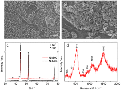
The effect of the reaction conditions on the glucose electrooxidation was investigated over NiO/Ni foam obtained by thermal treatment, since NiO is a good and stable catalyst for electrooxidation reactions.48 The calcination of the Ni foam at 500 °C for 1 h developed on the surface patches of a solid with ca. 150–300 nm thickness (Fig. 1a).49 A close look of the surface revealed that the patches were made of randomly oriented particles (Fig. 1b), which according to the XRD corresponded to crystalline NiO (Fig. 1c). EDS analysis confirmed a Ni/O atomic ratio of 1/1 (Fig. S1†). In the micro-Raman spectra (Fig. 1d), the activation of the 1P-LO mode at 540 cm−1 indicated that the NiO had some kind of disorder induced by defects, surface effects and/or imperfectness of the particles.50The CVs in a NaOH 0.1 M electrolyte without and with 0.05 M glucose are displayed in Fig. 2. Three consecutive CVs were recorded, all the figures show the third CV, which is similar to the first and second CVs. The redox Ni2+/Ni3+ peaks are recorded at 1.41 and 1.32 V vs. RHE in the pure NaOH electrolyte51,52 (Fig. 2, inset) and the onset of the OER occurred at ca. 1.6 V vs. RHE. The asymmetry of the Ni2+/Ni3+ peaks was related to the formation of different Ni(OH)2/NiOOH polymorphs.53,54 The Tafel slope of the OER was 68 mV dec−1. In the presence of glucose, the onset shifted to 1.2 V vs. RHE, a potential less anodic than the Ni2+/Ni3+ oxidation, while the current density in the high potential region was lowered. These results suggested, respectively, that the substrate oxidation could occur without the mediation of NiOOH species, as recently reported for gold,55 and that glucose lowered the OER contribution. An anodic current was recorded by reversing the potential, though the peak intensity was lower than in the forward going scan.32 The Tafel slope for the glucose oxidation was 130 mV dec−1, in a range similar to that reported by Holade et al. for a glucose dehydrogenation limiting step over Au,55 nevertheless it was much higher than the value previously reported for Ni foam (0.10 M glucose and 1.0 M KOH).26 To confirm the advantage of using a 3D support, the CV was also recorded in a calcined Ni plate (Fig. S2†). It was clear that the foam reached much higher current densities due to the larger surface area. The amount of Ni2+ species oxidized to Ni3+ in the calcined foam was estimated to be 3.1 × 10¹⁴.
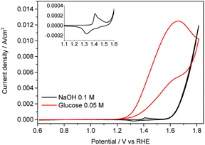 | ||
| Fig. 2 CVs in NaOH 0.1 M and glucose 0.05 M + NaOH 0.1 M over the NiO/Ni electrocatalyst. Conditions: 0.61–1.81 V vs. RHE; scan rate 5 mV s−1. | ||
Potential-dependent product distribution
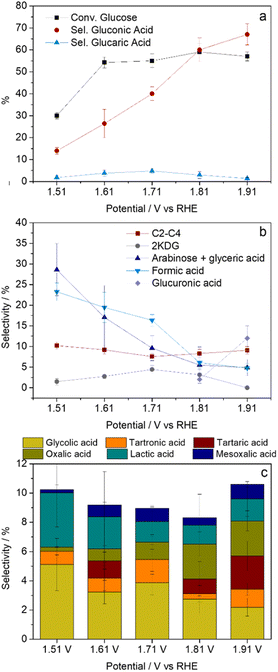
The potential-dependent product distribution was evaluated in the 1.51–1.91 V vs. RHE applied potential interval in a glucose 0.05 M in NaOH 0.1 M electrolyte. The values of conversion of glucose and selectivity in the reaction products are summarized in Fig. 3. The tests were performed keeping constant the potential applied and the charge accumulated (241 C, which corresponded to the coulombs required to fully oxidize the glucose molecules in the 0.05 M solution to gluconic acid, assuming a 2e− transfer process and 100% FE).Blank tests were performed with glucose (0.05 M) and gluconate (0.005 M) solutions (in NaOH 0.1 M) in contact with the NiO/Ni foam electrocatalyst, but in the absence of the applied potential. The isomerization of glucose to fructose occurred, the conversion of glucose was around 10%, no other relevant products were identified. A blank test with gluconate confirmed its stability in the electrolyte, discarding the contribution of homogeneous chemistry to the results. Note that the reactivity in the absence of the catalyst was lower than that in a thermocatalyzed process using O2 as the oxidant.11 The electrooxidation at 1.51 V vs. RHE proceeded quite slowly and only 114 C was accumulated after ca. 200 min, hence the values of conversion and selectivity displayed in Fig. 3 could not be directly compared with the results obtained at more anodic potentials. Taking into account these results, electrolysis at a less anodic potential (i.e., close to the onset of the CV) was not performed and the discussion in this section focuses on electrooxidations performed by applying potentials in the 1.61–1.91 V vs. RHE range.
The applied potential did not significantly modify the conversion of glucose (Fig. 3a) but the product distribution (Fig. 3b and c). The oxidation of the aldehyde group at C1 to the carboxylic acid occurred under all the electrolysis conditions, but the production of gluconic acid steadily increased as the potential became more anodic, reaching a maximum selectivity value of 66% at 1.91 V vs. RHE. Liu et al. also reported that over NiO/CNTs higher potentials were favorable for the selective conversion of glucose to gluconic acid.32 Similarly, the gluconic FE increased as the potential applied was more anodic, moving from ca. 10% ± 1 at 1.61 V to 22% ± 2 at 1.71 V, 32% ± 3 at 1.81 V, and 39% ± 3 at 1.91 V vs. RHE. Conversely, the more challenging oxidation of the alcohol in C6 to the carboxylic acid (glucaric acid) and to the intermediate aldehyde (glucuronic acid) barely took place. Glucuronic acid was only observed at 1.81 V vs. RHE. Meanwhile, the selectivity in glucaric acid was below 5%. It would appear that at 1.71 V vs. RHE a maximum in the glucaric acid production occurred; however, the low selectivity values made it rather difficult to provide an accurate explanation to the trend observed.
Side consecutive or parallel reactions also took place, leading to the formation of the by-products shown in Fig. 3b and c. The isomerization of glucose to fructose due to the basic pH (13) occurred during the reaction time, the final concentration of fructose was around 0.003–0.005 M, namely 6–10% of the initial glucose concentration. Note that no other main by-products besides fructose were obtained in blank tests. Once gluconic acid was produced, the more reactive secondary alcohol was oxidized to the ketone, though 2-ketogluconic acid (2KDG) was obtained in low yields (selectivity below 5%). The main by-products were arabinose/glyceric acid, formic acid and C2–C4 compounds. The contribution of the signal due to arabinose/glyceric acid and formic acid decreased as the potential became more anodic, while C2–C4 and 2KDG remained rather constant.
The impossibility of separating the real contribution of glyceric acid and arabinose made it difficult to precisely define the real reaction path; however, some hypothesis could be depicted (Scheme 2). Glucose or gluconic acid could follow a parallel decarboxylation pathway forming arabinose and formaldehyde; the latter was quickly oxidised to formic acid and likely to CO2. On the other hand, the C–C cleavage by retroaldol condensation, promoted by the electrooxidation and basic conditions, could form glyceraldehyde. This glyceraldehyde was further oxidized to glyceric acid, which then suffered from consecutive C–C cleavage and overoxidation reactions forming short chain carboxylic acids such as tartronic, mesoxalic, glycolic, and oxalic acids.56 Tartaric acid was also produced, however its selectivity did not follow a defined trend. Meanwhile, it could be stated that a high anodic potential promoted the formation of oxalic acid, namely the lastly obtained compound by the consecutive C–C cleavage and oxidation reactions. The selectivity in lactic acid, likely derived from fructose, roughly followed the opposite trend. The reactions performed at the more anodic potential were performed in a shorter time and the current density decreased with the reaction time (Fig. S3†), this could modify the isomerization side reaction.
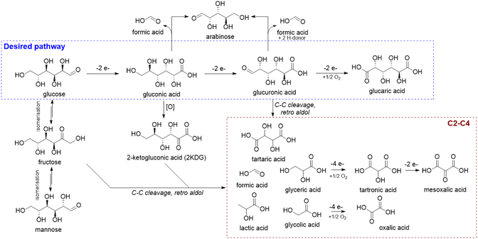 | ||
| Scheme 2 Possible reaction scheme for glucose electrooxidation in an alkaline environment. All the acids reported need to be considered as sodium salts in the presence of an excess of NaOH. | ||
To confirm that the results obtained were not modified due to alterations of the catalyst during the electrooxidation, after every electrolysis the spent NiO/Ni foam catalysts were chemically and electrochemically characterized. The behaviours below described were typical of all the catalysts, the figures and images corresponded to the catalyst tested at 1.81 V vs. RHE with 0.05 M glucose in 0.1 M NaOH electrolyte. The absence of nickel leaching was ascertained by analysing the composition of the electrolytes at the end of the reactions. SEM images and XRD patterns of the spent catalysts were pretty similar to those of the fresh catalysts, regardless of the reaction conditions (Fig. S4a and b†). However, by repeating the CVs of the NiO/Ni foam in 0.1 M NaOH and 0.05 M glucose in 0.1 M NaOH electrolytes at the end of the electrooxidations, it was observed that all the electrocatalysts tested showed increased activity in both the OER and glucose oxidation (Fig. S4c and d†). Ni catalysts likely activated under anodic conditions in basic media due to the increase in the Ni2+/Ni3+ couple, as shown in Ni L2,3 spectra in Fig. S5b,† and confirmed by the amount of Ni2+ species oxidized to Ni3+, which increased to 5.5 × 10¹⁴. It is agreed that the electrooxidation of glucose to gluconic acid proceeds through an indirect mechanism where NiOOH are the active species. XPS spectra of O 1s indicated the formation of NiOOH and Ni(OH)2 species after the electrooxidation reaction from a NiO thermal oxide (Fig. S6a†), which supported the mechanism here described. In this mechanism the slow step is the hydrogen transfer from glucose to the catalyst,57 hence it was expected that an enhanced electrochemical active Ni surface area promoted the electrocatalytic process,51,52,58 as well as the electrooxidation of shorter diols, like glycerol.59 Remarkably, the product distribution was rather constant when performing three repeated tests at 1.81 V vs. RHE (Fig. 4), although the XPS C 1s spectra confirmed the deposition of carbonaceous species (Fig. S6b†). The catalyst surface could be cleaned during the CVs. Note that the deposition of carbon on the surface of the electrode reduced significantly the signal of Ni 2p (see Fig. S6c†), which made the analysis difficult.
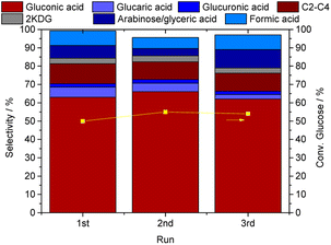 | ||
| Fig. 4 Conversion of glucose and selectivity in the reaction products in 3 consecutive runs performed at 1.81 V vs. RHE with a 0.05 M glucose in 0.01 M NaOH electrolyte. | ||
These results suggested that the activity of the NiO/Ni foam catalyst was rather stable. The increase in the Ni2+/Ni3+ redox pair and the activity in the OER may not play a significant role in the product distribution. Recently, the mechanism for the oxidation of alcohol and aldehyde functional groups over Ni catalysts was revised.60,61 Together with the indirect mechanism, it was stated that the hydride transfer involving NiO2 occurred at more positive potentials. It was claimed that the indirect mechanism was independent of the potential, conversely the hydride transfer increased at more anodic potentials (potential-dependent), where the NiO2 formation occurred. Since our electrooxidation of glucose was potential dependent, it could be inferred that the direct mechanism could play a role. A deeper study is in progress to better understand the active species involved in the process.
Evolution of the product distribution with the electrooxidation time
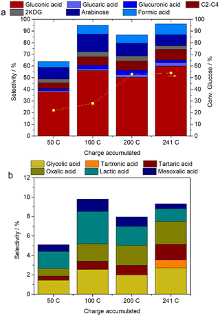
To better investigate the formation of side products during the electrooxidation at 1.81 V vs. RHE, aliquots of the electrolyte (glucose 0.05 M in NaOH 0.10 M) were withdrawn during the electrooxidation and analysed by HPLC. The results obtained after the accumulation of 50, 100, 200, and 241 C are shown in Fig. 5.Remarkably the production of gluconic acid increased in the first reaction period, i.e., until 100 C passed, Fig. 5a. Similarly, a slight increase in glucuronic and glucaric acids was observed over time. The mass balance was quite below 100% at 50 C, indicating the adsorption of some compounds on the surface of the catalyst or the formation of unknown compounds, such as humin precursors and heavy oligomers impossible to be quantified by chromatographic techniques. Moreover, aldol condensation reactions can be reversible (retro-aldol reactions) so this could also explain the C-balance trends observed. Among the identified by-products, the main differences were related to the formation of arabinose/glyceric acid, which reached a maximum at 100 C and progressively decreased up to 241 C. This behaviour was more evident at less anodic potentials (Fig. S7†), conditions more prone to the formation of by-products as shown in Fig. 3. At both 1.51 and 1.61 V vs. RHE, the arabinose/glyceric acid selectivity was above 30–40%. Arabinose and formic acid selectivity roughly followed the same trend, suggesting that the decarboxylation process was important and that this side-reaction was favoured at both short times and low applied potentials. About C2–C4 (Fig. 5b), the selectivity of lactic acid decreased and the oxalic acid production increased as the length of the reaction increased, following a similar trend to that with the applied potential.
The glucose isomerization, C–C cleavage and overoxidation side reactions are expected to be promoted as the reaction proceeded. Moreover, the consumption of glucose during the electrochemical reaction led to a decrease in its concentration at the electrode/electrolyte interface, which could foster the oxidation of intermediates23 and the contribution of the OER. Hence an electrooxidation test was performed with a more diluted 0.01 M glucose in 0.1 M NaOH electrolyte to mimic the decrease of the glucose concentration during the reaction time.
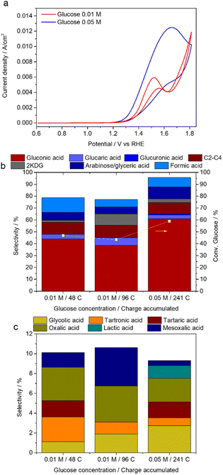
The CVs in Fig. 6a show that in a more diluted 0.01 M electrolyte the oxidation of glucose was almost complete at 1.7 V vs. RHE, the potential at which the OER discharge was observed. During the electrolysis at 1.81 V vs. RHE accumulating 48 C (stoichiometric charge) and 96 C, the glucose conversion and gluconic acid selectivity decreased in comparison to the 0.05 M electrolyte (Fig. 6b). The oxidation of the alcohol at C2 in gluconic acid, producing 2KDG (selectivity 9% for 96 C), and the formation of short chain carboxylic acids could explain this behavior (Fig. 6b and c). The oxidation of tartronic acid to mesoxalic acid likely occurred as the accumulated charge (reaction time) increased. Moreover, the formation of the oxalic acid was further promoted by dilution of the electrolyte. A lower glucose concentration likely decreased the glucose mass transfer and fostered the overoxidation of the reaction intermediates. This overoxidation could also be attributed to reactive OER intermediates, since the latter reaction would be favored by decreasing the glucose concentration.
Electrooxidation of fructose and gluconate
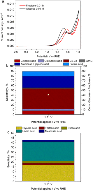
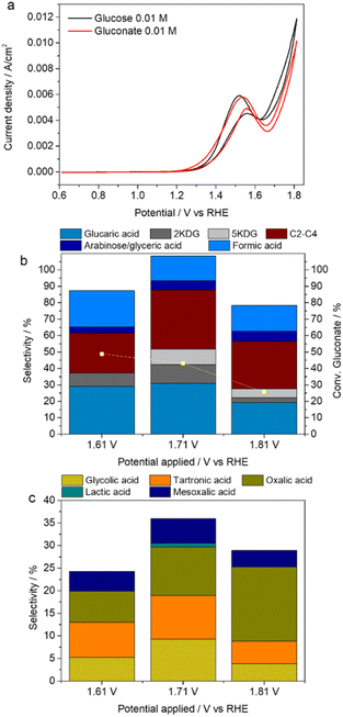
The aforementioned results confirmed the challenging nature of the glucose electrooxidation due to the isomerization to fructose and consecutive reactions of the gluconic acid produced such as overoxidation or C–C cleavage. To better understand these types of reactions, selected electrochemical tests were performed over NaOH 0.1 M electrolytes containing fructose (0.010 M) and gluconate (0.01 and 0.005 M).The feasibility of oxidizing fructose and gluconate at similar potentials to that of glucose over the NiO/Ni electrocatalyst was confirmed by CVs (Fig. 7a and 8a). This outcome implied that not only both substrates will compete in the electrochemical process for the charge and active sites but also the oxidation peak was not structure sensitive. Despite the CV resemblances, the product distributions during the electrolysis at 1.81 V were different, in agreement with the catalytic/chemical reactivity of the compounds.
Fructose primarily underwent C–C bond cleavage during the electrooxidation (Fig. 7b), in agreement with previous reports.24,36 The major reaction products were C2–C4, arabinose/glyceric acid and formic acid. Interestingly, as previously reported by Ostervold et al.36 fructose followed the same reactivity trend as in thermocatalysis,62 reaching high lactic and glycolic acid selectivities, 20 and 17% respectively (Fig. 7c). The C–C cleavage by retroaldol condensation was likely responsible for the formation of glyceraldehyde and dihydroxyacetone. Glyceraldehyde could be electrooxidized to glyceric acid or decarboxylated to glycolic acid. On the other hand, dihydroxyacetone likely formed pyruvaldehyde and ultimately lactic acid.
The electrooxidation of the 0.010 M gluconate in NaOH 0.1 M electrolyte at 1.81 V vs. RHE produced glucaric acid (Fig. 8b and c), confirming that the electrooxidation process over the NiO/Ni catalyst, allowed, at least partially, to selectively oxidize the alcohol at C6 into the carboxylic acid. However, the glucaric acid selectivity was still only ca. 20%. The oxidation of C2 in gluconate (selectivity 2KDG 3%) and the isomerization of glucuronic acid to 5-ketogluconic acid (5KDG) were consecutive reactions that likely decreased the yield of glucaric acid. The C–C cleavage/retroaldol in C3 and oxidation reactions formed tartronic and glyceric acids, which evolved towards the formation of mesoxalic and glycolic acids, respectively, to obtain finally large quantities of oxalic acid (Fig. 8c).
To decrease the overoxidation products, the electrochemical oxidation was performed at lower potentials, 1.71 and 1.61 V vs. RHE (Fig. 8b and c). Glucaric acid (30%), 2KDG (11%) and 5KDG (9%) selectivities improved, mainly at 1.71 V vs. RHE. Simultaneously the formation of oxalic acid decreased, suggesting that overoxidation reactions were partially suppressed; however, the contributions of C2–C4 and formic acid were still very high. The glucaric acid FE reached a maximum value of 23% at 1.71 V vs. RHE.
An electrooxidation test with a more diluted 0.005 M gluconate in NaOH 0.10 M electrolyte at 1.71 V vs. RHE (Fig. 9) demonstrated that the oxidation of the alcohol at C2 readily happened, i.e., 2KDG selectivity was as high as 62% after 12 C accumulated. The 2KDG then underwent C–C cleavage and overoxidation reactions to form C2–C4 and formic acid. Remarkably the glucaric acid selectivity increased during the reaction time. However, the glucaric acid FE steadily decreased from 17% at 12 C, 14% at 24 and 36 C, and finally to 10% at 48 C, probably related to the lower gluconate concentration and therefore a higher contribution of the OER.
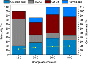 | ||
| Fig. 9 Evolution of gluconate conversion and product distribution during the electrolysis of a 0.005 M gluconate in NaOH 0.1 M solution at 1.71 V vs. RHE. Charge accumulated 48 C. | ||
The results suggested that once gluconic acid was formed the oxidation of the alcohol at C2 and the C–C cleavage were likely the main causes for the decrease in the gluconic acid selectivity. The blank tests with gluconate did not reveal any significant homogeneous contribution to the C–C cleavage, hence this side reaction could be related to the interaction of glucose with the electrocatalyst, as previously reported for glycerol.63 In electrocatalysis it is well established that the glucose molecule in the pyranose configuration adsorbs at the C1 position (anomeric carbon) either through the hydrogen directly bound to the C (β-anomer) or to the O (α-anomer), nevertheless under our reaction conditions (basic media) the β-anomer is agreed to be the most reactive.55 The gluconolactone formed is then hydrolyzed, opening the ring and forming gluconate, which could be adsorbed on the electrocatalyst surface and further reacted; the existence of vicinal OH groups favored the C–C cleavage. The consecutive reactions involving the C2–C4 molecules could be both chemically and electrochemically promoted. The former could be attributed to the instability of the products in the high pH electrolyte, as previously reported for glycerol derived products.56 The electrochemical reactions consumed the charge, and therefore further limited the glucose conversion.
Effect of the glucose/NaOH ratio
The pH is a key parameter to control the selectivity of the glucose oxidation both in thermochemical and electrochemical processes.11,25 During electrooxidations performed in the 1.61–1.81 V vs. RHE range, the pH of the electrolyte decreased from 13 to 12. Note that a calculation on the theoretical amount of NaOH required for the observed product distribution during the three repeated tests at 1.81 V vs. RHE in Fig. 4 (i.e., due to the salification of the formed organic acids plus one NaOH for every acidic functionality produced11) showed a depletion of NaOH around 56% which nonetheless should lead to an almost negligible pH decrease from 13 to 12.6 respectively, in good accordance with the value experimentally observed. More studies are in progress to validate this assumption.To gain insight into the role of OH− species in the electroactivity, 0.05 M glucose solutions with stoichiometric, excess and defect amounts of OH− (considering a glucose/OH− stoichiometric value of 1/2) were prepared, which corresponded to pHs 13, 14, and 12.7.
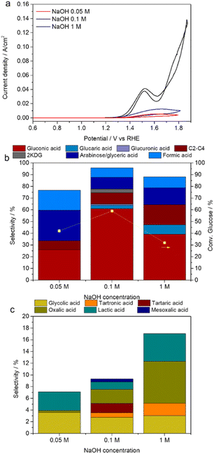
The increase in the NaOH concentration from 0.05 to 1 M led to a more intense and well-defined anodic glucose peak as well as to its shift towards less anodic potentials, Fig. 10a. Moreover, as expected, the OER discharge largely increased in the NaOH 1 M electrolyte (Fig. S8†); however, there was no apparent correlation between the area of the Ni2+/Ni3+ peaks and NaOH concentration.
Despite the clear improvement in the electrocatalytic activity observed in the CVs as the solution became more basic, the electrolysis at 1.81 V vs. RHE over the 0.05 M glucose electrolyte evidenced that the use of 1 M NaOH did not provide any significant benefit in terms of product distribution (Fig. 10b and c), only the glucaric acid production slightly increased. In contrast, both glucose conversion and selectivity in gluconic acid were reduced (Fig. 10b), and the gluconic acid FE dropped to 12%. Simultaneously, the formation of C2–C4 was boosted (selectivity ca. 17%), oxalic acid and lactic acid being the main side products.
The effect of pH was complex in the electrochemical reaction system, the pH determined the OER, the stability of glucose and the reaction products. A high NaOH concentration (pH 14) promoted glucose isomerization to fructose that through consecutive reactions, as above explained, gave lactic acid. Other side reactions were C–C cleavage by retro-aldol condensation, overoxidation and decarboxylation of the C3 product up to oxalic acid. Remarkably, a decrease in the NaOH concentration did not provide any improvement as well; the formation of gluconic-derived products (2KDG and glucaric acid) was not observed, and the arabinose/glyceric acid and formic acid production was favoured. These results indicated that both a low and a high NaOH concentration were detrimental to the electroactivity.
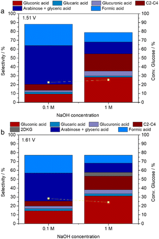
By analysing the CVs in Fig. 10a it was shown that the increase in the concentration of NaOH provoked a large enhancement in the activity at potentials less anodic than the OER, hence, to decrease the consecutive side reactions several reactions were performed at lower applied potentials. The decrease of the applied potential to 1.71 V vs. RHE did not provoke any performance improvement (Fig. S9†). Conversely, by further decreasing the potential applied at 1.51 and 1.61 V vs. RHE and keeping the reaction time short (100 C accumulated) the gluconic acid selectivity was twice for the 1 M NaOH electrolyte than for the 0.10 M electrolyte, and a slight increase in glucaric acid selectivity was observed (Fig. 11). Simultaneously, the formation of arabinose/gluconic acid and formic acid largely decreased, while the selectivity in C2–C4 by-products was enhanced significantly.
Conclusions
The electrooxidation of glucose, in the presence of a well-defined and characterized NiO/Ni foam electrode, was deeply investigated. In particular, the product distribution obtained during the tests was found to be highly dependent on the reaction parameters which were interrelated. Interestingly, the oxidation of glucose to gluconic acid was a kinetically primary reaction which readily happened in the presence of a minimum (i.e., 2× the stoichiometric value) amount of base leading to gluconic acid yields of about 33%, a value which is fairly stable for at least three cycles, demonstrating the stability of the NiO/Ni foam electrocatalyst. On the other hand, the consecutive oxidation of the alcohol at C6 to glucaric acid was also feasible; however, the reaction could not be selectively limited to the activation of these groups leading to the formation of a wide variety of side products. The potential applied, NaOH concentration and the reaction time are likely the main parameters to be controlled to further optimize the process; nonetheless, the role of adsorption of intermediates and mass transfer could not be overlooked.Conflicts of interest
There are no conflicts to declare.Acknowledgements
This work was funded by the “Alma Idea” project from the Alma Mater Studiorum-University of Bologna. The authors thank Alantum for supplying foam and Dr Franco Corticelli for the FE-SEM measurements.References
- H. G. J. de Wilt, Ind. Eng. Chem. Prod. Res. Dev., 1972, 11, 370 CrossRef CAS.
- J. M. H. Dirkx, H. S. Van Der Baan and J.-M. A. J. J. Van Den Broek, Carbohydr. Res., 1977, 59, 63 CrossRef CAS.
- Z. Zhang and G. W. Huber, Chem. Soc. Rev., 2018, 47, 1351 RSC.
- L. T. Mika, E. Cséfalvay and Á. Németh, Chem. Rev., 2018, 118, 505 CrossRef CAS PubMed.
- J. Iglesias, I. Martínez-Salazar, P. Maireles-Torres, D. Martin Alonso, R. Mariscal and M. López Granados, Chem. Soc. Rev., 2020, 49, 5704 RSC.
- Q. Zhang, Z. Wan, I. K. M. Yu and D. C. W. Tsang, J. Cleaner Prod., 2021, 312, 127745 CrossRef CAS.
- T. N. Smith, K. Hash, C. L. Davey, H. Mills, H. Williams and D. E. Kiely, Carbohydr. Res., 2012, 350, 6 CrossRef CAS PubMed.
- S. Donen and K. Jensen, US Pat., 20140275622 (A1), Rivertop Renewables Inc., 2014.
- P. Pal, R. Kumar and S. Banerjee, Chem. Eng. Process., 2016, 104, 160 CrossRef CAS.
- T. R. Boussie, E. L. Dias, Z. M. Fresco, V. J. Murphy, J. Shoemaker, R. Archer, and H. Jiang, US Pat., 2010317823 (A1), Rennovia Inc., 2010.
- S. Solmi, C. Morreale, F. Ospitali, S. Agnoli and F. Cavani, ChemCatChem, 2017, 9, 2797 CrossRef CAS.
- K. Saeed, P. Priecel and J. A. Lopez-Sanchez, Chem. Today, 2017, 35, 7 CAS.
- J.-I. Yoshida, K. Kataoka, R. Horcajada and A. Nagaki, Chem. Rev., 2008, 108, 2265 CrossRef CAS PubMed.
- Y. Holade, K. Servat, S. Tingry, T. W. Napporn, H. Remita, D. Cornu and K. B. Kokoh, ChemPhysChem, 2017, 18, 2573 CrossRef CAS PubMed.
- N. Neha, B. S. R. Kouamé, T. Rafaïdeen, S. Baranton and C. Coutanceau, Electrocatal, 2021, 12, 1 CrossRef CAS.
- Z. Fan, W. Zhang, L. Li, Y. Wang, Y. Zou, S. Wang and Z. Chen, Green Chem., 2022, 24, 7818 RSC.
- B. You, X. Liu, N. Jiang and Y. Sun, J. Am. Chem. Soc., 2016, 138, 13639–13646 CrossRef CAS PubMed.
- H. Luo, J. Barrio, N. Sunny, A. Li, L. Steier, N. Shah, I. E. L. Stephens and M.-M. Titirici, Adv. Energy Mater., 2021, 11, 2101180 CrossRef CAS.
- J. Miao, X. Teng, R. Zhang, P. Guo, Y. Chen, X. Zhou, H. Wang, X. Sun and L. Zhang, Appl. Catal., B, 2020, 263, 118109 CrossRef CAS.
- F. Arshad, T. Haq, I. Hussain and F. Sher, ACS Appl. Energy Mater., 2021, 4, 8685 CrossRef CAS.
- R. Li, K. Xiang, Z. Peng, Y. Zou and S. Wang, Adv. Energy Mater., 2021, 11, 2102292 CrossRef CAS.
- C. Lemoine, Y. Holad, L. Dubois, T. W. Napporn, K. Servat and K. B. Kokoh, J. Electroanal. Chem., 2021, 887, 115162 CrossRef CAS.
- T. Rafaïdeen, S. Baranton and C. Coutanceau, Appl. Catal., B, 2019, 243, 641 CrossRef.
- G. Moggia, T. Kenis, N. Daems and T. Breugelmans, ChemElectroChem, 2019, 6, 1 CrossRef.
- G. Moggia, J. Schalck, N. Daems and T. Breugelmans, Electrochim. Acta, 2021, 374, 137852 CrossRef CAS.
- W.-J. Liu, Z. Xu, D. Zhao, X.-Q. Pan, H.-C. Li, X. Hu, Z.-Y. Fan, W.-K. Wang, G.-H. Zhao, S. Jin, G. W. Huber and H.-Q. Yu, Nat. Commun., 2020, 11, 265 CrossRef CAS PubMed.
- L. Zhao, X. Kuang, X. Sun, Y. Zhang and Q. Wei, J. Electrochem. Soc., 2019, 166, H534 CrossRef CAS.
- K. B. Kokoh, J. M. Leger, B. Beden, H. Huser and C. Lamy, Electrochim. Acta, 1992, 37, 1909 CrossRef CAS.
- M. Tominaga, T. Shimazoe, M. Nagashima and I. Taniguchi, Electrochem. Commun., 2005, 7, 189 CrossRef CAS.
- D. Li, Y. Huang, Z. Li, L. Zhong, C. Liu and X. Peng, Chem. Eng. J., 2022, 430, 132783 CrossRef CAS.
- W. Zheng, Y. Li, C.-S. Tsang, P.-K. So and L. Y. S. Lee, iScience, 2021, 24, 102342 CrossRef CAS PubMed.
- Z. Liu and Y. Shen, ACS Appl. Energy Mater., 2022, 5, 11723 CrossRef CAS.
- S. Biella, L. Prati and M. Rossi, J. Catal., 2002, 206, 242 CrossRef CAS.
- J. Lee, B. Saha and D. G. Vlachos, Green Chem., 2016, 18, 3815–3822 RSC.
- Y. Holade, A. B. Engel, K. Servat, T. W. Napporn, C. Morais, S. Tingry, D. Cornu and K. B. Kokoh, J. Electrochem. Soc., 2018, 165, H425 CrossRef CAS.
- L. Ostervold, S. I. Perez Bakovic, J. Hestekin and L. F. Greenlee, RSC Adv., 2021, 11, 31208 RSC.
- N. Govindarajan, A. Xu and K. Chan, Science, 2022, 375, 379 CrossRef CAS PubMed.
- Y. B. Vasil’ev, O. A. Khazova and N. N. Nikolaeva, J. Electroanal. Chem. Interfacial Electrochem., 1985, 196, 127 CrossRef.
- A. Abbadi and H. van Bekkum, J. Mol. Catal. A: Chem., 1995, 97, 111 CrossRef CAS.
- A. Abbadi, M. Makkee, W. Visscher, J. A. R. van Veen and H. van Bekkum, J. Carbohydr. Chem., 1993, 12, 573 CrossRef CAS.
- W. M. Corbett and A. M. Liddle, J. Chem. Soc., 1961, 531 RSC.
- B. Y. Yang and R. Montgomery, Carbohydr. Res., 1996, 280, 27 CrossRef CAS.
- Y. Miao, L. Ouyang, S. Zhou, L. Xu, Z. Yang, M. Xiao and R. Ouyang, Biosens. Bioelectron., 2014, 53, 428 CrossRef CAS PubMed.
- K. E. Toghill and R. G. Compton, Int. J. Electrochem. Sci., 2010, 5, 1246 CrossRef CAS.
- D.-W. Hwang, S. Lee, M. Seo and T. D. Chung, Anal. Chim. Acta, 2018, 1033, 1 CrossRef CAS PubMed.
- Q. Dong, H. Ryu and Y. Lei, Electrochim. Acta, 2021, 370, 137744 CrossRef CAS.
- C. Wang, Y. Wu, A. Bodach, M. L. Krebs, W. Schuhmann and F. Schüth, Angew. Chem., Int. Ed., 2023, e202215804 CAS.
- Y. Yuan, Y. Guo, W. Wu, Z. Mao, H. Xu and Y. Ma, ACS Energy Lett., 2022, 7, 3276 CrossRef CAS.
- J. M. Roemers-van Beek, Z.-J. Wang, A. Rinaldi, M. G. Willinger and L. Lefferts, ChemCatChem, 2018, 10, 3107 CrossRef CAS.
- P. Ravikumar, B. Kisan and A. Perumal, AIP Adv., 2015, 5, 087116 CrossRef.
- V. Ganesh, S. Farzana and S. Berchmans, J. Power Sources, 2011, 196, 9890 CrossRef CAS.
- P. Yang, X. Tong, G. Wang, Z. Gao, X. Guo and Y. Qin, ACS Appl. Mater. Interfaces, 2015, 7, 4772 CrossRef CAS PubMed.
- S. R. Mellsop, A. Gardiner, B. Johannessen and A. T. Marshall, Electrochim. Acta, 2015, 168, 356 CrossRef CAS.
- Š. Trafela, J. Zavašnik, S. Šturm and K. Ž. Rožman, Electrochim. Acta, 2020, 362, 137180 CrossRef.
- Y. Holade, H. Guesmi, J.-S. Filhol, Q. Wang, T. Pham, J. Rabah, E. Maisonhaute, V. Bonniol, K. Servat, S. Tingry, D. Cornu, K. B. Kokoh, T. W. Napporn and S. D. Minteer, ACS Catal., 2022, 12, 12563 CrossRef CAS.
- M. K. Goetz, M. T. Bender and K.-S. Choi, Nat. Commun., 2022, 13, 5848 CrossRef CAS PubMed.
- M. Fleischmann, K. Korinek and D. Pletcher, J. Chem. Soc., Perkin Trans. 2, 1972, 10, 1396 RSC.
- Š. Trafela, J. Zavašnik, S. Šturm and K. Ž. Rožman, Electrochim. Acta, 2020, 362, 137180 CrossRef.
- R. Garcia Da Silva, S. Aquino Neto, K. Boniface Kokoh and A. Rodrigues De Andrade, J. Power Sources, 2017, 351, 174 CrossRef.
- M. T. Bender, Y. Choi Lam, S. Hammes-Schiffer and K.-S. Choi, J. Am. Chem. Soc., 2020, 142, 21538 CrossRef CAS PubMed.
- M. T. Bender, R. E. Warburton, S. Hammes-Schiffer and K.-S. Choi, ACS Catal., 2021, 11, 15110 CrossRef CAS.
- L. Li, F. Shen, R. Smith and X. Qi, Green Chem., 2017, 19, 76–81 RSC.
- M. S. E. Houache, K. Hughes and E. A. Baranova, Sustainable Energy Fuels, 2019, 3, 1892–1915 RSC.
Footnote |
| † Electronic supplementary information (ESI) available. See DOI: https://doi.org/10.1039/d3se00847a |
| This journal is © The Royal Society of Chemistry 2023 |


