 Open Access Article
Modulation of wetting of stimulus responsive polymer brushes by lipid vesicles: experiments and simulations†
Felix
Weissenfeld‡
a,
Lucia
Wesenberg‡
b,
Masaki
Nakahata
cd,
Marcus
Müller
 *b and
Motomu
Tanaka
 *ae
*ae
aPhysical Chemistry of Biosystems, Institute of Physical Chemistry, Heidelberg University, 69120 Heidelberg, Germany. E-mail: tanaka@uni-heidelberg.de
bInstitute for Theoretical Physics, Georg-August University, Friedrich-Hund-Platz 1, 37077 Göttingen, Germany. E-mail: mmueller@theorie.physik.uni-goettingen.de
cDepartment of Materials Engineering Science, Graduate School of Engineering Science, Osaka University, 560-8531 Osaka, Japan
dDepartment of Macromolecular Science, Graduate School of Science, Osaka University, 560-8531 Osaka, Japan
eCenter for Advanced Study, Institute for Advanced Study, Kyoto University, 606-8501 Kyoto, Japan
First published on 21st March 2023
Abstract
The interactions between vesicle and substrate have been studied by simulation and experiment. We grafted polyacrylic acid brushes containing cysteine side chains at a defined area density on planar lipid membranes. Specular X-ray reflectivity data indicated that the addition of Cd2+ ions induces the compaction of the polymer brush layer and modulates the adhesion of lipid vesicles. Using microinterferometry imaging, we determined the onset level, [CdCl2] = 0.25 mM, at which the wetting of the vesicle emerges. The characteristics of the interactions between vesicle and brush were quantitatively evaluated by the shape of the vesicle near the substrate and height fluctuations of the membrane in contact with brushes. To analyze these experiments, we have systematically studied the shape and adhesion of axially symmetric vesicles for finite-range membrane–substrate interaction, i.e., a relevant experimental characteristic, through simulations. The wetting of vesicles sensitively depends on the interaction range and the approximate estimates of the capillary length change significantly, depending on the adhesion strength. We found, however, that the local transversality condition that relates the maximal curvature at the edge of the adhesion zone to the adhesion strength remains rather accurate even for a finite interaction range as long as the vesicle is large compared to the interaction range.
1 Introduction
Physical contact of cells to their neighbors – cell adhesion – plays a key role in a wide variety of biological processes. Cell adhesion modulates a number of biochemical signaling pathways1,2 and tissue morphogenesis driven by forces acting between neighboring cells.3 On the other hand, impaired cell adhesion function is often associated with diseases, such as cancer metastasis. A significant reduction of cell–cell and cell–matrix adhesion causes the invasive migration and release of cancer cells into blood circulation.4 Ample evidence has indicated that cell adhesion is not only a static attachment between cells but also highly dynamic. For example, the freshwater polyp Hydra is able to regenerate the complete body with a new head and foot by de novo pattern formation from dissociated single cells by sorting cell–cell contacts.5,6 On the molecular level, an increasing number of experimental studies have shown that the dynamic rearrangement of adhesion molecules and their ligands plays critical roles in immunological response7 and cell apoptosis.8 Such experimental findings have been qualitatively recapitulated by using a phenomenological model of adhesion-induced phase separation9 or by assuming the presence of strong pinning centers.10 However, the quantitative combination of experiments and simulations still remains challenging.Therefore, a large number of studies so far have been performed to physically model cell adhesion using rather simple, artificial lipid vesicles in the presence and absence of specific ligand–receptor-like interaction pairs (stickers). Cell adhesion in equilibrium has been described within the framework of wetting physics, irrespective of the different origins of adhesion on the molecular level.11–14 In analogy to the shape of liquid drops on substrates, the shape of a cell or a lipid vesicle can be fine-tuned by tailoring the membrane–substrate interaction, V(z), that quantifies the free energy of placing a unit area of the membrane a distance, z, away from the substrate. V(z) is characterized by the interplay of short- and long-range forces. Notably, what makes “biological” droplets, such as cells and lipid vesicles, distinct from droplets of simple liquid is the interface between the interior and exterior; the bilayer lipid membrane. The intrinsic physical property of lipid bilayer membranes is their bending rigidity, κ, whereas the bilayer tension, γ, depends on the membrane geometry. Conversely, the tension of the liquid–vapor interface of a liquid drop is an intrinsic property, independent of the drop shape.15–17 Another difference is that the shape of an adhered vesicle is dictated by the balance between adhesion and bending free energies, whereas the shape of a liquid drop is determined by balancing adhesion and interface tension. The latter balance – resulting in Young's equation18 for the contact angle of a drop – remains invariant under scale changes of the liquid drop, whereas the former balance explicitly depends on the vesicle size, R0. Thus, one can systematically study the adhesion of vesicles by varying the vesicle size, leaving the substrate chemistry unaltered.
From the experimental viewpoint, the use of soft polymer substrates is a straightforward strategy to finely adjust the adhesion of vesicles by tuning vesicle–substrate interaction, V(z). Planar lipid membranes deposited on polymer substrates – called polymer-supported membranes19 – have been used as soft “cushions” that reduce the frictional coupling of membranes and membrane-associated proteins by preventing direct contact.20,21 Previously, we measured specular neutron and X-ray reflectivity of zwitterionic phosphatidylcholine membranes deposited on about 20 and 40 nm-thick cellulose supports.22 The equilibrium distance between the membrane and underlying Si substrates determined by experiments could be reproduced by calculating the disjoining pressure including van der Waals, hydration, and Helfrich-undulation repulsion, quantitatively.
To switch the adhesion of vesicles, the use of stimulus responsive polymer brushes is a promising strategy, as they can change their physical properties (conformation, degrees of ionization, solvent affinity, etc.) by external cues, such as changes in temperature, pH, light, and ions.23–31 Previously, we transferred pH-responsive diblock copolymers from the air/water interface to solid substrates and demonstrated the change in polymer-chain conformation by pH titration. Intriguingly, the reversible change in polymer chain conformation led to a switching of the water layer between the membrane and brushes.32
In this study, we designed switchable polymer-brush substrates that can switch V(z) by forming chelator complexes with divalent ions in a concentration-dependent manner. We synthesized polyacrylic acid brushes containing cysteine side chains terminated with biotin (PAA-Cys5-biotin) based on the hypothesis that –COOH and –SH side chains form a complex with Cd2+ ions with a high affinity.33 To achieve a uniform grafting of brushes at a defined grafting density, we grafted the polymer chains onto supported membranes doped with biotin-functionalized lipids via neutravidin crosslinkers, instead of the commonly used “grafting onto” strategy.34,35 Owing to the extremely high affinity of biotin and neutravidin, KD ≈ 10−15 M,36 the average grafting distance, 〈d〉 can be controlled at nm accuracy simply by the doping ratio of biotin lipids (see Methods for more details). In contrast to previous studies, which induced the change in areal charge density by a drastic change in solution pH37 or salt concentrations,38 PAA-Cys5 brushes enable us to switch the conformation and hence V(z) in the presence of 100 mM NaCl with 10 mM Tris buffer (pH 7.4), where the change in the total ionic strength and pH is negligible. The change in thickness, roughness, and density of the polymer brush layer was monitored by specular X-ray reflectivity, while the curvature of the effective membrane–substrate interaction was calculated from the height fluctuation of the membranes in contact with brushes. The global shape of vesicles (side view) was reconstructed from the confocal fluorescence microscopy images and compared to the theory.
In the simulation, we represent the membrane by a thin elastic sheet within the Helfrich model15 that has previously been utilized to study the adsorption of vesicles.12,13,39–41 We are describing the shape through a Fourier expansion around a spherical vesicle.42,43 Numerically minimizing the bending and adhesion, we determine the optimal shape of the vesicle paying particular attention to the effect of a finite range of the interaction, V, between membrane and substrate. This effect is present in the experiment and has to be accounted for in the quantitative analysis.
Our manuscript is arranged as follows: in the next section, we introduce the experimental system and methods, followed by a description of the simulation model and numerical techniques. In the result section, we study the thermodynamics of adhesion and vesicle shape and present results on the experimental switching of the brush and the curvature of the vesicle–brush interaction. The manuscript closes with a brief summary and outlook.
2 Materials, models, and methods
2.1 Experimental materials
2.2 Methods
 | (1) |
The reflectivity for each data point was corrected for the beam footprint and for the beam intensity. A generic minimization algorithm of the Parratt formalism47 implemented in the Motofit software48 was used to fit the experimental data.
 | (2) |
I
i
represents the intensity of the light reflected at the ith interface, and  is the wave vector. n is the refractive index of the buffer (n = 1.344), λ the wavelength (λ = 475 nm), and Φ the phase shift of the reflected light. To monitor the height fluctuation δz(t), we collected the mean intensity from 3 × 3 pixels as a function of time I(t):
 | (3) |
2.3 Model and numerical techniques
For the numerical minimization of the vesicle (free) energy, we expand ψ(s) around a spherical vesicle in a Fourier series42,43
 | (4) |
The position of the axially symmetric vesicle membrane takes the form
 | (5) |
 | (6) |
We represent the bending energy by the Helfrich Hamiltonian, ![[script letter H]](https://www.rsc.org/images/entities/char_e142.gif) b, that expresses the energy costs via a surface integral over the two principal curvatures, C1 and C2.15 Using the parameterization, ψ(s), these curvatures take the form13,41,42
b, that expresses the energy costs via a surface integral over the two principal curvatures, C1 and C2.15 Using the parameterization, ψ(s), these curvatures take the form13,41,42
 | (7) |
 | (8) |
 | (9) |
 and subsequent quantities is performed numerically in the zr-plane by discretizing the parametric vesicle shape, r(s), z(s) into Ns points. Using a trapezoidal integration, the error is on the order Ns−2.
Whereas prior studies often modeled the interaction between vesicle membrane and substrate per unit area by a contact potential12,13,41 (see ref. 39 for an exception), we consider short-range potentials, Vc(z), with a finite width, σw, and long-range potentials, Vw(z), that represent van der Waals interactions. The two types of potentials are illustrated in Fig. 3. The origin of the z-axis is the minimum of the membrane–substrate potential, and −Δγw denotes the value of the membrane–substrate potential at its minimum. The short-range potential is given by
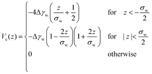 | (10) |
 | (11) |
 shifts the minimum of Vw(z) to z = 0. We note that the long-range power-law decay is scale-free.
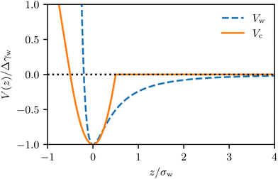 | ||
| Fig. 3 Illustration of the long-range and short-range membrane–substrate interactions, Vw(z) and Vc(z), according to eqn (10) and (11). | ||
Integrating the membrane–substrate interaction over the vesicle, we obtain the adhesion energy
 | (12) |
Instead of characterizing the range of the potential by σw, we can use the curvature, V′′, of the potential at its minimum. The latter quantity controls the experimentally accessible, thermal height fluctuations of a membrane, bound to the substrate (cf. Section 3.3). For the two types of potential, we respectively obtain
 | (13) |
 | (14) |
![[script letter H]](https://www.rsc.org/images/entities/char_e142.gif) 0[ψ,z0,Ls] ≡
0[ψ,z0,Ls] ≡ ![[script letter H]](https://www.rsc.org/images/entities/char_e142.gif) b +
b + ![[script letter H]](https://www.rsc.org/images/entities/char_e142.gif) w, under the following constraints: (i) fixed membrane area, A[ψ] = 4πR02 and (ii) vesicle closure, r(Ls) = 0. Additionally, we could enforce (iii) the volume, V0, enclosed by the vesicle. Numerically, the constraints are mollified, and the resulting restraints are incorporated into the energy functional via umbrella potentials with large spring constants.
w, under the following constraints: (i) fixed membrane area, A[ψ] = 4πR02 and (ii) vesicle closure, r(Ls) = 0. Additionally, we could enforce (iii) the volume, V0, enclosed by the vesicle. Numerically, the constraints are mollified, and the resulting restraints are incorporated into the energy functional via umbrella potentials with large spring constants.
Deviations of the membrane area, A[ψ,Ls], from the reference value, A0 = 4πR02, increase the energy by an amount
 | (15) |
 | (16) |
| γ = kA(A[ψ,Ls] − 4πR02) | (17) |
Likewise, vesicle closure, r(Ls) = 0, gives rise to the contribution
 | (18) |
For completeness, we mention that deviations of the enclosed volume  from a reference value, V0, could be penalized by an energy contribution
 | (19) |
The total energy, ![[script letter H]](https://www.rsc.org/images/entities/char_e142.gif) =
= ![[script letter H]](https://www.rsc.org/images/entities/char_e142.gif) 0 + δH, to be minimized contains the bending and adhesion energies, and the restraints, δH = HA + Hr + HV. In the following, we measure all energies in units of the membrane's bending rigidity, κ, and all length scales in units of the radius, R0, of a spherical vesicle with the same membrane area as the restraint, A0.
0 + δH, to be minimized contains the bending and adhesion energies, and the restraints, δH = HA + Hr + HV. In the following, we measure all energies in units of the membrane's bending rigidity, κ, and all length scales in units of the radius, R0, of a spherical vesicle with the same membrane area as the restraint, A0.
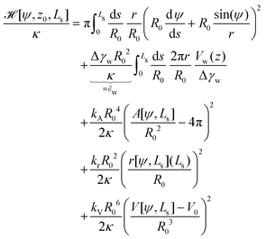 | (20) |
 (ref. 12 and 13) that measures the relative strength of adhesion with respect to the bending energy. As a consequence, we can vary this dimensionless characteristic by changing the vesicle size, R0, without altering the membrane–substrate interaction, V(z).
The energy functional,  , is numerically minimized with respect to ψ, z0, Ls by a conjugate-gradient method. Typical parameter values are compiled in Table 1. The values that minimize
  are denoted by
  ; these values depend on the thermodynamic state, specified by
 ![[small epsilon, Greek, tilde]](https://www.rsc.org/images/entities/i_char_e0de.gif) w. Inserting these values into the energy functional, we obtain the energy,
w. Inserting these values into the energy functional, we obtain the energy,  of the vesicle at a given thermodynamic state. Note that this procedure completely ignores thermal fluctuations.
| Variable | Value |
|---|---|
| N max | 128, 144 |
| N s | 288, 578, 2048 |
| σ w/R0 | 0.03, 0.01 or 0.002 |
![[k with combining tilde]](https://www.rsc.org/images/entities/i_char_006b_0303.gif) A ≡ kAR04/κ
A ≡ kAR04/κ |
100 |
![[k with combining tilde]](https://www.rsc.org/images/entities/i_char_006b_0303.gif) V ≡ kVR06/κ
V ≡ kVR06/κ |
0, permeable membrane |
![[k with combining tilde]](https://www.rsc.org/images/entities/i_char_006b_0303.gif) r ≡ krR02/κ
r ≡ krR02/κ |
1000 |
To study the adhesion transition we quantify the dimensionless energy difference between the vesicles in contact with a substrate and a free, unbound vesicle H = 8πκ
 | (21) |
3 Results
3.1 Validity of the transversality condition for finite-ranged membrane–substrate interaction
Fig. 4a presents the vesicle shape for long-range interaction, Vw, with σw = 0.002R0 and various adhesion strengths,![[small epsilon, Greek, tilde]](https://www.rsc.org/images/entities/i_char_e0de.gif) w. Upon increasing
w. Upon increasing ![[small epsilon, Greek, tilde]](https://www.rsc.org/images/entities/i_char_e0de.gif) w, the vesicle gradually spreads on the substrate. As shown in Fig. 4b, the confocal side views of vesicles in the absence (green) and presence (red) of attractive interactions qualitatively exhibit good agreement.
w, the vesicle gradually spreads on the substrate. As shown in Fig. 4b, the confocal side views of vesicles in the absence (green) and presence (red) of attractive interactions qualitatively exhibit good agreement.
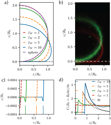 | ||
Fig. 4 Vesicle shape for long-range interactions. (a) Shape of the axially symmetric vesicle, r(s), z(s), for various ![[small epsilon, Greek, tilde]](https://www.rsc.org/images/entities/i_char_e0de.gif) w as indicated in the key and comparison to a spherical vesicle. (b) Vesicle shapes obtained in the absence (green) and presence (red) of attractive interactions by experiments showing the same qualitative tendency. (c) Detail of the vesicle shape at the edge of the adhesion zone, exhibiting a dent, i.e., a ring with z(s) < 0. The vertical lines mark the geometric radius of the contact zone, eqn (25), obtained by the position of maximal curvature. (d) First principal curvature, w as indicated in the key and comparison to a spherical vesicle. (b) Vesicle shapes obtained in the absence (green) and presence (red) of attractive interactions by experiments showing the same qualitative tendency. (c) Detail of the vesicle shape at the edge of the adhesion zone, exhibiting a dent, i.e., a ring with z(s) < 0. The vertical lines mark the geometric radius of the contact zone, eqn (25), obtained by the position of maximal curvature. (d) First principal curvature,  , as a function of the arc-length parameter, s. Note the negative values of the curvature at the edge of the adhesion zone. The lines at the ordinate axis indicate the maximal-curvature estimate, , as a function of the arc-length parameter, s. Note the negative values of the curvature at the edge of the adhesion zone. The lines at the ordinate axis indicate the maximal-curvature estimate,  according to the transversality condition, eqn (22). (The dotted line presents fits, C1(s) = C1max according to the transversality condition, eqn (22). (The dotted line presents fits, C1(s) = C1max![[thin space (1/6-em)]](https://www.rsc.org/images/entities/char_2009.gif) exp(−[s − smax]/λE) beyond the maximum at smax, analog to eqn (31).) exp(−[s − smax]/λE) beyond the maximum at smax, analog to eqn (31).) | ||
For small ![[small epsilon, Greek, tilde]](https://www.rsc.org/images/entities/i_char_e0de.gif) w = 1 – the pinned state39 – the vesicle shape is very close to a sphere, yet the vesicle benefits from the long-range attraction. We note that the second-order wetting transition for zero-ranged interactions at
w = 1 – the pinned state39 – the vesicle shape is very close to a sphere, yet the vesicle benefits from the long-range attraction. We note that the second-order wetting transition for zero-ranged interactions at ![[small epsilon, Greek, tilde]](https://www.rsc.org/images/entities/i_char_e0de.gif) wc = 2 is rounded. Instead, the thermodynamic transition is a first-order and occurs at
wc = 2 is rounded. Instead, the thermodynamic transition is a first-order and occurs at ![[small epsilon, Greek, tilde]](https://www.rsc.org/images/entities/i_char_e0de.gif) w = 0 for σw > 0 (vide infra).
w = 0 for σw > 0 (vide infra).
Fig. 4c depicts a detail of the vesicle shape in the contact zone, where one can appreciate a small dent at the edge of the adhesion zone. Such a nonmonotonic behavior of the distance, z(s), between membrane and substrate results from the simultaneous optimization of the adhesion energy and bending energy. The width of this dent increases with σw. Vertical lines at the axis indicate the geometric radius of the contact area, extracted from the maximum of the first principal curvature. One can observe that both, the location of the dent and the maximal curvature, provide a rather faithful estimate of the edge of the adhesion zone.
The first principal curvature, C1(s), along the vesicle is shown in Fig. 4d. For a contact potential, σw → 0, the curvature jumps from 0 inside the contact zone to a finite value that is dictated by the transversality condition12,13
(C1maxR0)2 = 2![[small epsilon, Greek, tilde]](https://www.rsc.org/images/entities/i_char_e0de.gif) w for w for![[thin space (1/6-em)]](https://www.rsc.org/images/entities/char_2009.gif) contact contact![[thin space (1/6-em)]](https://www.rsc.org/images/entities/char_2009.gif) interactions interactions | (22) |
![[small epsilon, Greek, tilde]](https://www.rsc.org/images/entities/i_char_e0de.gif) w. For σw > 0, there is no jump singularity of C1 but the curvature exhibits a rapid, sigmoidal variation at the edge of the adhesion zone. For potentials, V, with a nonzero interaction range, Evans suggested using the maximal curvature, C1max, instead of the contact curvature in the transversality condition.51 Note that the transversality condition systematically underestimates the maximal curvature. Panel (d) of Fig. 4 reveals that the dent at the edge of the adhesion zone gives rise to negative C1-values. Thus, the jump in C1 that emerges in the limit σw → 0 can alternatively be estimated by the change, ΔC1 ≡ C1max − C1min, of curvature at the edge of the adhesion zone.
w. For σw > 0, there is no jump singularity of C1 but the curvature exhibits a rapid, sigmoidal variation at the edge of the adhesion zone. For potentials, V, with a nonzero interaction range, Evans suggested using the maximal curvature, C1max, instead of the contact curvature in the transversality condition.51 Note that the transversality condition systematically underestimates the maximal curvature. Panel (d) of Fig. 4 reveals that the dent at the edge of the adhesion zone gives rise to negative C1-values. Thus, the jump in C1 that emerges in the limit σw → 0 can alternatively be estimated by the change, ΔC1 ≡ C1max − C1min, of curvature at the edge of the adhesion zone.
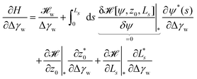
To further study the effects of the long-range potential, we observed the contact area of the adsorbed vesicle. There is no singularity at the edge of the adhesion zone but the vesicle shape gradually detaches from the substrate (vide infra). We can define a thermodynamic contact area via the first derivative of the energy,  , with respect to the adhesion strength, Δγw.
 | (23) |
 | (24) |
rgeoc = r(arg![[thin space (1/6-em)]](https://www.rsc.org/images/entities/char_2009.gif) maxsdψ/ds) maxsdψ/ds) | (25) |
 | (26) |
These estimates of the contact area, according to eqn (24) (solid lines, open symbols) and eqn (26) are shown in Fig. 5a. Both definitions exhibit qualitatively similar behaviors but Ãgeoc is slightly but consistently larger than Ãthc. The so-defined contact area continuously increases with ![[small epsilon, Greek, tilde]](https://www.rsc.org/images/entities/i_char_e0de.gif) w, and it approaches a constant value for
w, and it approaches a constant value for ![[small epsilon, Greek, tilde]](https://www.rsc.org/images/entities/i_char_e0de.gif) w → 0 in the pinned state, where the vesicle benefits from the potential but is hardly deformed. For a repulsive substrate,
w → 0 in the pinned state, where the vesicle benefits from the potential but is hardly deformed. For a repulsive substrate, ![[small epsilon, Greek, tilde]](https://www.rsc.org/images/entities/i_char_e0de.gif) w < 0, the vesicle is unbound and the contact area vanishes. The discontinuity of the contact area at
w < 0, the vesicle is unbound and the contact area vanishes. The discontinuity of the contact area at ![[small epsilon, Greek, tilde]](https://www.rsc.org/images/entities/i_char_e0de.gif) w = 0 marks the first-order adhesion transition. This behavior differs significantly from the second-order transition at
w = 0 marks the first-order adhesion transition. This behavior differs significantly from the second-order transition at ![[small epsilon, Greek, tilde]](https://www.rsc.org/images/entities/i_char_e0de.gif) w = 2 predicted for a contact potential behavior.12,13
w = 2 predicted for a contact potential behavior.12,13
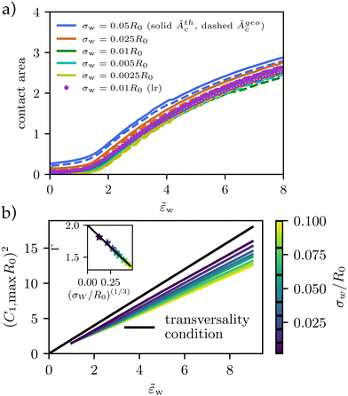 | ||
Fig. 5 Vesicle shape for long-range potential, Vw, with scale σw = 0.002R0 as a function of adhesion strength, ![[small epsilon, Greek, tilde]](https://www.rsc.org/images/entities/i_char_e0de.gif) w as indicated in the key. (a) Thermodynamic and geometric contact area, Ãthc, and Ãgeoc, as a function of adhesion strength, w as indicated in the key. (a) Thermodynamic and geometric contact area, Ãthc, and Ãgeoc, as a function of adhesion strength, ![[small epsilon, Greek, tilde]](https://www.rsc.org/images/entities/i_char_e0de.gif) w, for short-range and long-range potentials of varying width, σw. (b) For potentials approaching a contact potential, the transversality condition is met. For wider potentials, the curvature increases slower with increasing adhesion strength (compare eqn (27)). As shown in the inset, Γ decreases from 2 with (σw/R0)(1/3). w, for short-range and long-range potentials of varying width, σw. (b) For potentials approaching a contact potential, the transversality condition is met. For wider potentials, the curvature increases slower with increasing adhesion strength (compare eqn (27)). As shown in the inset, Γ decreases from 2 with (σw/R0)(1/3). | ||
Thus, it is warranted to validate the transversality condition, eqn (22), for finite interaction ranges, σw > 0. In Fig. 5b, we explore the influence of the finite potential range on the transversality condition. We observe, that the linear relation between ![[small epsilon, Greek, tilde]](https://www.rsc.org/images/entities/i_char_e0de.gif) w and (C1maxR0)2 remains valid, however, the slope and offset are specific to the details of the membrane–substrate interaction
w and (C1maxR0)2 remains valid, however, the slope and offset are specific to the details of the membrane–substrate interaction
(C1maxR0)2 ≈ Γ![[small epsilon, Greek, tilde]](https://www.rsc.org/images/entities/i_char_e0de.gif) w + Δ w + Δ | (27) |
![[small epsilon, Greek, tilde]](https://www.rsc.org/images/entities/i_char_e0de.gif) w because the vesicle profits still from the potential at some distance and hence large curvatures are energetically not favorable.
w because the vesicle profits still from the potential at some distance and hence large curvatures are energetically not favorable.
For the large vesicles used in the experiment, σw/R0 ≪ 1, however, the slope, Γ, is close to 2 and we use eqn (22) to calculate the adhesion free energy, Δγw.
3.2 Characterization of switchable substrates coated with stimulus-responsive polymer brushes
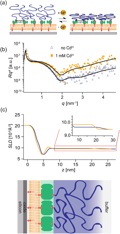
PAA-Cys5-biotin brushes were grafted on the surface of DOPC membranes deposited on planar solid substrates (supported membranes) doped with 2 mol% DOPE-biotin neutravidin crosslinkers. The supported membranes were prepared by the fusion of small unilamellar vesicles (cf. Section 2.2.1). The major advantage of supported membranes over the commonly used, direct grafting of polymers onto solid substrates via covalent bonds (called “grafting onto” method) is their capability to achieve high and well-defined grafting densities. As DOPC and DOPE-biotin are miscible, the average grafting distance 〈d〉 can be controlled at nm accuracy simply by the molar fraction of DOPE-biotin χbiotin, 〈d〉 = (0.6/χbiotin)0.5 [nm], assuming the area per lipid molecule is 0.6 nm2.52 As schematically shown in Fig. 6a, our previous study using quartz crystal microbalance with dissipation suggested that the binding of Cd2+ ions to PAA-Cys5 leads to the compaction of brushes. High-energy X-ray reflectivity experiments were performed to verify the structural changes of PAA-Cys5 brushes. Note that the use of high energy (17.48 keV from Mo Kα) was necessary to guarantee the sufficiently high transmittance of X-ray beam through bulk water.53,54Fig. 6b shows the X-ray reflectivity data and the best fit results (solid lines, Fig. 6b). Fig. 6c shows the scattering length density (SLD) profiles reconstructed from the best fit model (upper panel) and the correspondence to the layer structure (lower panel). The addition of 1 mM Cd2+ ions caused a clear change in the global shape of the X-ray reflectivity (Fig. 6b), suggesting that PAA-Cys5-biotin brushes change their conformation. The layer parameters obtained from the best fit results (Table 2) and the magnified SLD profiles in the vicinity of the interface (Fig. 6c, inset) suggest that the brush layer thickness decreased from d0 = 14.3 nm to dCd = 10.3 nm, accompanied by the decrease in the brush/solution interface roughness from σ0 = 2.0 nm to σCd = 1.2 nm. The obtained results indicate that PAA-Cys5-biotin brushes become more compact in the presence of 1 mM Cd2+ ions, resulting in a sharper transition from the brush region to the bulk solution (Fig. 6a). The compaction of PAA-Cys5-biotin caused by additional Cd2+ ions suggests that the negative charges carried by –COOH side chains were compensated by the binding of Cd2+ ions.55 In fact, the zeta potential of PAA-Cys5-biotin brushes grafted on supported membranes deposited on SiO2 microparticles (radius: 1.5 μm) showed a monotonic increase from ζ1μM = −26 mV to ζ1mM = −10 mV.55 This qualitatively agrees well with previous reports, showing that the decrease in the ionization degree of side chains results in the compaction of polyelectrolyte brushes.32 It should be noted that the addition of 1 mM Cd2+ ions does not alter the pH (7.4) or Debye screening length (κD−1 < 10 Å) because the solution contains 100 mM NaCl buffered with 10 mM Tris (pH 7.4). In fact, Yamamoto et al. systematically varied the side chain moieties and demonstrated that not only –COOH groups but also the coexistence of –SH groups are necessary to achieve the sensitive capture of Cd2+ ions.33 Further spectroscopic studies, under the systematic variations of the side chain functionalities, will help us understand the molecular-level mechanism of interactions between Cd2+ ions and PAA-Cys5.| PAA-Cys5-biotin in the absence of Cd2+ | |||
|---|---|---|---|
| d (nm) | SLD (10−6 Å−2) | σ (nm) | |
| SiO2 | 1.23 ± 0.03 | 18.9 | 0.55 ± 0.01 |
| Buffer | 0.46 ± 0.01 | 9.45 | 0.45 ± 0.02 |
| Lipid headgroupinner | 0.68 ± 0.01 | 13.1 ± 0.2 | 0.47 ± 0.01 |
| Lipid alkylchain | 2.24 ± 0.03 | 6.8 ± 0.01 | 0.59 ± 0.02 |
| Lipid headgroupouter | 0.89 ± 0.05 | 12.3 ± 0.2 | 0.62 ± 0.06 |
| Neutravidin+ | 18.2 ± 0.8 | 9.7 ± 0.1 | 2.05 ± 0.1 |
| PAA-Cys5-biotin | |||
| PAA-Cys5-biotin in the presence of 1 mM Cd2+ | |||
|---|---|---|---|
| d (nm) | SLD (10−6 Å−2) | σ (nm) | |
| SiO2 | 1.19 ± 0.04 | 18.9 | 0.51 ± 0.01 |
| Buffer | 0.48 ± 0.01 | 9.45 | 0.44 ± 0.03 |
| Lipid headgroupinner | 0.67 ± 0.02 | 12.9 ± 0.3 | 0.44 ± 0.03 |
| Lipid alkylchain | 2.21 ± 0.04 | 7.1 ± 0.02 | 0.59 ± 0.03 |
| Lipid headgroupouter | 0.88 ± 0.07 | 12.3 ± 0.4 | 0.57 ± 0.06 |
| Neutravidin+ | 14.2 ± 1.2 | 9.9 ± 0.1 | 1.20 ± 0.11 |
| PAA-Cys5-biotin | |||
3.3 Experimental modulation of wetting by lipid vesicles
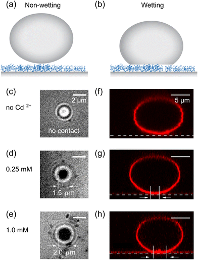
Panels (a and b) of Fig. 7 schematically show a “non-wetting vesicle” hovering on the brush-coated substrate and a “wetting vesicle” establishing a stable adhesion contact to the brush-coated substrate, respectively. To judge whether the vesicle established a stable adhesion contact or not, we visualized the DOPC vesicles by reflection interference contrast microscopy (RICM) from below at [CdCl2] = 0 mM, 0.25 mM and 1.0 mM, cf.Fig. 7(c–e). In addition, the global shape of the vesicle was reconstructed from the confocal fluorescence microscopy images, and the cross-sectional side view was extracted by slicing the vesicle in the middle plane (Fig. 7f–h). Here, the density of liquid inside was adjusted to be slightly higher than the buffer outside (Δρ = 40 kg m−3) in order that the vesicles sediment towards the substrate surface.The RICM image taken in the absence of Cd2+ ions showed a faint dark spot at the center of a bright disk, whose intensity fluctuates over time. This indicates that the vesicle sediments due to the density difference but does not adhere onto the substrate.21,49 In fact, the side view of the vesicle reconstructed from the confocal image stacks shows no sign of wetting (Fig. 7f). In contrast, the RICM image of a vesicle taken at [CdCl2] = 0.25 mM shows a stable dark disk due to the destructive interference (Fig. 7d). This suggests that the vesicle establishes a stable adhesion/wetting contact to the brush-coated substrate. Notably, the formation of a flat vesicle-substrate contact can hardly be detected from the confocal side view (Fig. 7g). When we increased the concentration of Cd2+ ions, the wetting of brush-coated substrate with lipid vesicles became more pronounced, which can be characterized by a large adhesion contact (Fig. 7e) and a clear flattening of the bottom (Fig. 7h). By screening Cd2+ ion concentration systematically, we verified that the adhesion contact can be detected only at [CdCl2] ≥ 0.25 mM. To verify the reproducibility of our experimental finding, several sets of confocal (Fig. S1, ESI†) and RICM (Fig. S2, ESI†) are presented in ESI.† These data demonstrated that RICM is very sensitive to detecting the onset of “(partial) wetting” of soft substrates by lipid vesicles, which can hardly be detected by the confocal side view.
Previously, Nardi et al. showed the change in vesicle-substrate interactions by using vesicles incorporating cationic lipids interacting with supported membranes doped with negatively charged lipids.56 The pH modulation caused changes in the surface charge density, where they observed the breakdown of Young–Dupré-type wetting by the formation of the three-dimensional protrusion (blisters). In contrast the confocal images of lipid vesicles indicated that the vesicles showed no sign of adhesion on lipid membranes with no PAA-Cys5 brushes, independent of the presence or absence of 1 mM Cd2+ ions (Fig. S3, ESI†). This could be attributed to the fact that our experiments were performed in the presence of 10 mM Tris buffer, which is much milder than the conditions used in the previous report of Lis et al.57 As shown in Fig. 6, our PAA-Cys5-coated substrates showed a clear change in the thickness and roughness by a slight change in Cd2+ ion concentration in 100 mM NaCl buffered with 10 mM Tris. This enables us to modulate the “wetting” state of vesicles without changing pH or electrochemical screening. Furthermore, as demonstrated in our previous study, PAA-Cys5 brushes, possessing both –SH and –COOH side chains like naturally occurring phytochelatin and metallothionein proteins,58,59 selectively react to a subtle change in [CdCl2].55 As the switching of PAA-Cys5 brushes does not require any temperature changes, such as poly(N-isopropylacrylamide) (PNIPAAm) brushes,60 PAA-Cys5 brushes allow to avoid hydrodynamic perturbation by thermal convection.
3.4 Determination of adhesion-free energy from experimental data
Fig. 8a shows a typical RICM image of a DOPC vesicle adhered on a PAA-Cys5-coated substrate. To gain high counting statistics, the signal intensity was radially integrated over azimuth angle ϕ (Fig. 8b). The height profile shown in Fig. 8c was reconstructed by an inverse cosine transformation of the radially integrated RICM signal intensity (Fig. 8b).14 What differentiates the wetting by lipid vesicles from that by a droplet of a simple fluid is that the height profile of the membrane in the vicinity of the substrate is dominated by the bending elasticity. On larger scales, the global shape of vesicles is governed by the geometry-dependent membrane tension, γ. The transition from the elasticity-dependent height profile to the tension-dominated vesicle profile occurs on the scale of the capillary length,14,61,62 | (28) |
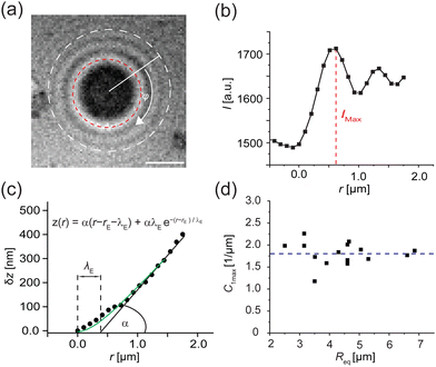 | ||
| Fig. 8 Determination of adhesion free energy Δγw at [CdCl2] = 1 mM. (a) A typical RICM image of a vesicle adhered on a PAA-Cys5-coated substrate at [CdCl2] = 1 mM. Scale bar: 2 μm. (b) Radially integrated RICM signal intensity versus distance from the center. The line coincides with the fitting with eqn (30). (c) Membrane height z versus the distance r, reconstructed from the fitting shown in panel (b). (d) Contact curvature C1max plotted versus the radius of each vesicle at the plane of equator Req. | ||
For zero-ranged, contact interaction between membrane and substrate, the minimization of the vesicle energy in Monge representation,41,61
| λγ2∇4z − ∇2z = 0 | (29) |
i.e., λγ sets the scale of the profile in the vicinity of the substrate. Bruinsma wrote down a one-dimensional solution62 that fulfills the boundary conditions, z = 0, dz/dr = 0, and C1max = d2z/dr2 = α/λE at the edge of the adhesion zone, r = rE.§
| z(r) = α(r − rE − λE) + αλEe−(r−rE)/λE | (30) |
Within the Monge representation, s ≈ r, and eqn (30) yields for the curvature,
 | (31) |
![[small epsilon, Greek, tilde]](https://www.rsc.org/images/entities/i_char_e0de.gif) w, is. For larger s, however, the Monge representation becomes inappropriate and C1(s) does not decay to zero but to a constant value that characterizes the cap-shaped, upper half of the vesicle, i.e., eqn (30) fails to capture the tension-dominated, cap shape of the vesicle profile far away from the edge of the adhesion zone, (r − rE)/λE ≫ 1.
w, is. For larger s, however, the Monge representation becomes inappropriate and C1(s) does not decay to zero but to a constant value that characterizes the cap-shaped, upper half of the vesicle, i.e., eqn (30) fails to capture the tension-dominated, cap shape of the vesicle profile far away from the edge of the adhesion zone, (r − rE)/λE ≫ 1.
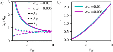 | ||
Fig. 9 (a) Dependence of different estimates of capillary length – λγ according to eqn (28), the extrapolation length λ1 from a cap-shape approximation (see Fig. 2b), and the length λE extracted from the height profile in the ultimate vicinity of the edge of the adhesion zone – on the adhesion strength, ![[small epsilon, Greek, tilde]](https://www.rsc.org/images/entities/i_char_e0de.gif) w. The figure presents data for two different interaction ranges, σw, as indicated in the key. (b) Membrane tension, w. The figure presents data for two different interaction ranges, σw, as indicated in the key. (b) Membrane tension, ![[small gamma, Greek, tilde]](https://www.rsc.org/images/entities/i_char_e0dd.gif) = γR02/κ, as a function of adhesion strength, = γR02/κ, as a function of adhesion strength, ![[small epsilon, Greek, tilde]](https://www.rsc.org/images/entities/i_char_e0de.gif) w. w. | ||
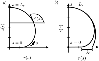
In Fig. 9, we systematically investigate the two geometric estimates of the capillary length – λ1 as depicted in Fig. 2b and λE obtained by fitting eqn (31) – and compare these data with the definition, λγ, according to eqn (28).
For λ1, we consider the 18% of the data closest to s = Ls and fit a sphere. This spherical cap is characterized by its radius, Rcap, and the height of the top, z(Ls). Given the radius, rE, of the edge of the adhesion zone, λ1, is obtained.
For λE, we first determine the value, C1max. Then, λE is estimated from eqn (31) by a one-parameter fit in the vicinity of r ≳ rE, as illustrated by the dashed lines in Fig. 4d.
The comparison of the two data sets with different ranges, σw, of membrane–substrate interactions reveals that this local characteristic is largely independent of σw, similar to the behavior of the transversality condition.
The three different estimates, however, differ for small ![[small epsilon, Greek, tilde]](https://www.rsc.org/images/entities/i_char_e0de.gif) w and only appear to converge to a common value for large adhesion strength. Given the involved approximation, rE ≪ λγ, these deviations are expected. For small adhesion strength,
w and only appear to converge to a common value for large adhesion strength. Given the involved approximation, rE ≪ λγ, these deviations are expected. For small adhesion strength, ![[small epsilon, Greek, tilde]](https://www.rsc.org/images/entities/i_char_e0de.gif) w, the vesicle is nearly spherical and the geometry-dependent tension is very small. Upon increasing
w, the vesicle is nearly spherical and the geometry-dependent tension is very small. Upon increasing ![[small epsilon, Greek, tilde]](https://www.rsc.org/images/entities/i_char_e0de.gif) w, we observe a rather pronounced decrease of λγ. λE obtained from the decay of the curvature at the edge of the adhesion zone also decreases with the adhesion strength,
w, we observe a rather pronounced decrease of λγ. λE obtained from the decay of the curvature at the edge of the adhesion zone also decreases with the adhesion strength, ![[small epsilon, Greek, tilde]](https://www.rsc.org/images/entities/i_char_e0de.gif) w, but the dependence is significantly weaker. The estimate, λ1, that is extracted from the overall shape of the vesicle, assuming a cap shape, even displays the opposite
w, but the dependence is significantly weaker. The estimate, λ1, that is extracted from the overall shape of the vesicle, assuming a cap shape, even displays the opposite ![[small epsilon, Greek, tilde]](https://www.rsc.org/images/entities/i_char_e0de.gif) w-dependence at small adhesion strength. This finding highlights the challenge of accurately estimating the membrane–vesicle interactions via analytical but approximate descriptions of the vesicle shape.
w-dependence at small adhesion strength. This finding highlights the challenge of accurately estimating the membrane–vesicle interactions via analytical but approximate descriptions of the vesicle shape.
The experimentally determined height profiles were fitted with eqn (30) up to z ≈ 300 nm. As reported previously,20,21α was determined by the intersection of the linear fit (black line) with the abscissa with λE determined from the fit (Fig. 8c).
Independent of the specific functional form, eqn (30), of the fit of the vesicle profile at the adhesion edge, we utilize the fit to compute the contact curvature  . In Fig. 8d, the contact curvature C1max was plotted versus the vesicle radius at the plane of the equator, Req. As expected, C1max, is independent of the vesicle size.
Using the previously reported bending rigidity of DOPC vesicles, κ = 24kBT,46 and the transversality condition, eqn (22), our experimental data (Fig. 8d) yielded the average adhesion free energy, Δγw ≈ 41kBT/μm2, which is comparable with the free energy of integrin-mediated vesicle adhesion.20,21 Depending on the vesicle size, R0, these values give rise to a dimensionless adhesion strength of ![[small epsilon, Greek, tilde]](https://www.rsc.org/images/entities/i_char_e0de.gif) w = ΔγwR02/κ ≈ 1.71(R0/μm)2 ≈ 7 or 84 for R0 = 2 μm and 7 μm, respectively. Thus, the experimental data are in the strong adhesion regime,
w = ΔγwR02/κ ≈ 1.71(R0/μm)2 ≈ 7 or 84 for R0 = 2 μm and 7 μm, respectively. Thus, the experimental data are in the strong adhesion regime, ![[small epsilon, Greek, tilde]](https://www.rsc.org/images/entities/i_char_e0de.gif) w ≫ 2.
w ≫ 2.
Analogously, the adhesion free energy at [CdCl2] = 0.25 mM, Δγw ≈ 24kBT/μm2 was calculated.
3.5 Modulation of interfacial potential V(z) calculated from experimental data
To quantitatively determine the curvature of the effective membrane–substrate potential, V(z), between vesicles and substrates coated with PAA-Cys5 brushes, we monitored the height fluctuation of adhesion zones by recording RICM movies over time. As averaging the signal intensity over a large membrane patch or the camera's shot noise could smear the local membrane height fluctuation due to the macroscopic membrane undulation and the shot noise,63 we selected 3 small regions (3 × 3 pixels corresponding to 0.096 μm2) near the center of the adhesion zone and monitored the mean intensity fluctuation inside each region (Fig. 10a). Using eqn (3) we computed the laterally averaged height fluctuations, δz =![[z with combining macron]](https://www.rsc.org/images/entities/i_char_007a_0304.gif) − 〈z〉 where
− 〈z〉 where ![[z with combining macron]](https://www.rsc.org/images/entities/i_char_007a_0304.gif) stands for the lateral average of the membrane height in a small 3 × 3 pixel region and 〈z〉 = 0 denotes the height average over the entire membrane patch of macroscopic dimension, L.
stands for the lateral average of the membrane height in a small 3 × 3 pixel region and 〈z〉 = 0 denotes the height average over the entire membrane patch of macroscopic dimension, L.
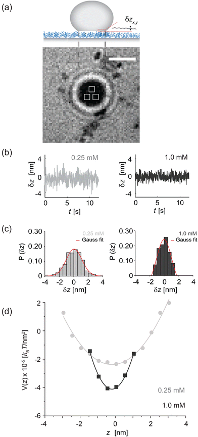 | ||
| Fig. 10 Modulation of membrane fluctuation by [CdCl2]. (a) The intensity fluctuations collected from three independent locations in the adhesion zone (3 × 3 pixels each, indicated by white boxes) were converted to the height fluctuation following eqn (3). Scale bar: 2 μm. (b) Laterally averaged membrane–substrate distance, δz, plotted versus time at [CdCl2] = 0.25 mM (grey) and 1 mM (black). (c) Probability of fluctuation amplitude P(δz) calculated from the data presented in panel b. (d) Effective membrane–substrate potential, V(z) calculated versus z. The potential curvature V′′(z = 0) or the “spring constant” represents the sharpness of membrane confinement, while the potential minima correspond to the adhesion free energy Δγw determined by microinterferometry.8 | ||
Panel (b and c) of Fig. 10 show the height fluctuations, δz(t), monitored at 30 ms per frame for 12 s and the distribution of fluctuation amplitudes, P(δz), measured at [CdCl2] = 0.25 mM (grey) and 1.0 mM (black), respectively. As shown in Fig. 10c, P(δz) determined by experiments are well approximated by a Gaussian distribution.
In order to extract the curvature,  of the membrane–substrate interaction from the measured variance, 〈δz2〉, we consider an almost planar membrane patch, |∇z| ≪ 1, in contact with the substrate and use the Monge representation
 | (32) |
 | (33) |
 | (34) |
![[z with combining tilde]](https://www.rsc.org/images/entities/i_char_007a_0303.gif) q denotes the two-dimensional Fourier transform of z(x,y) and L the length of a membrane patch. In equilibrium, the Fourier modes are Gaussian distributed with zero mean and variance
q denotes the two-dimensional Fourier transform of z(x,y) and L the length of a membrane patch. In equilibrium, the Fourier modes are Gaussian distributed with zero mean and variance | (35) |
 .
.
The resolution of microscopy is determined by the pixel size which is 103 nm for the microscope used in this study. Thus the membrane fluctuation is laterally averaged over a scale Δ3p ≫ ξ‖
 | (36) |
Using eqn (35) and (36), we calculate 〈δz2〉
 | (37) |
This analysis allows us to estimate the curvature of the membrane–substrate interaction, V′′, near the average height of an adhered membrane patch. We extracted the variance of the height fluctuations from Fig. 10b and c, and calculated,  and
and  (n = 15), for the two Cd2+ ion concentrations respectively. The clear increase in V′′ caused by a subtle increase in [CdCl2] implied that the membrane patch in the adhesion zone is more sharply confined near the brush-coated substrate. As shown in Fig. 10c, the probability of local height fluctuation, P(δz), is well approximated by a Gaussian and thus the shape of the potential in Fig. 10d resembles the orange curve, Vc, depicted in Fig. 3, at least in the vicinity of the minimum at z = 0.
It should be noted that the microinterferometric analysis of membrane height fluctuation enables to characterize the potential curvature V′′ corresponding to the “spring constant” of a harmonic oscillator but not the absolute potential energy minimum Δγw, i.e., the adhesion energy per unit area. Therefore, we took the experimentally determined mean squared amplitude of fluctuation 〈δz2〉 and adhesion free energy Δγw and calculated the absolute interfacial potential V(z) using eqn (33). In Fig. 10d the absolute interfacial potentials for the different Cd2+ ion concentrations are shown, which results in potential minima of Δγw,0.25mM ≈ 24kBT/μm2 and Δγw,1.0mM ≈ 41kBT/μm2.
Using vesicles adhering to micropatterned steps, Schmidt et al. showed that the membrane–substrate potential of vesicles becomes nonharmonic,63 which takes a similar shape as the blue curve presented in Fig. 3. The main difference between the two experimental systems is that the amplitude of height fluctuation on our PAA-Cys5 brushes is several nm, indicating that the membrane is confined in the close vicinity of the potential minimum. On the other hand, the membrane on micropatterned steps fluctuates by tens of nm where the long-range interactions can be detected due to a large membrane–substrate distance (∼100 nm).
4 Conclusions
We synthesized a cysteine-modified polyacrylic acid polymer, PAA-Cys5, that changes the conformation in the presence of Cd2+ ions in a concentration-dependent fashion, and grafted the brushes on supported membranes at the controlled grafting distance 〈d〉 = 6 nm. Specular X-ray reflectivity data indicated the compaction of PAA-Cys5 layer at [CdCl2] = 1 mM (Fig. 6), which modulates the wetting by the phospholipid vesicles by varying Cd2+ ion concentrations. As the onset of stable contact zones is strongly linked to an increase in potential strength, we can reference this to the change in brush conformation. Thus, by carefully observing the vesicle–brush contact zone by microinterferometry, we observed the onset of wetting at, [CdCl2] = 0.25 mM (Fig. 7). The analysis of the height fluctuation of membranes and the shape of vesicles near the substrate enabled us to determine the curvature of the membrane–substrate interaction, V′′(z) (Fig. 10), contact curvature C1max, and the adhesion free energy Δγw (Fig. 8).We have studied the shape and thermodynamics of vesicles on stimulus responsive substrates. Whereas most previous studies focus on the idealized situation of zero-ranged contact interaction in the absence of buoyancy (see ref. 39 and 40 for exceptions), we pay particular attention to the potential range as this is relevant to experiments. However, the long-range potential has only a minor influence on the maximal curvature at the edge of the adhesion zone (see Fig. 5), slightly adapting the coefficient of the transversality condition that is commonly employed to relate the contact curvature to the adhesion strength, given a scale separation between potential range and vesicle size. We want to emphasize, that the combination of simulation and experiment enables us to determine the absolute interfacial potential V(z) with Δγw as the potential minimum.
Author contributions
MN synthesized the polymer. FW performed the experiment and analyzed the experimental data. LW supported the data analysis and performed the simulations. MM and MT designed the research, acquired funding, and supervised the project. FW, LW, MM, and MT discussed the data, and all the authors contributed to writing the manuscript.Conflicts of interest
There are no conflicts to declare.Acknowledgements
The authors thank the Deutsche Forschungsgemeinschaft (DFG) within the priority program SPP2171 under grant numbers Mu1674/17-1 (to MM) and Ta253/14-1 (to MT), and the JSPS KAKANHI under the grant number JP19H05719 (to MT and MN) for financial supports. FW thanks Nikon Imaging Center Heidelberg for the support to confocal microscopy imaging. LW and MM gratefully acknowledge the Gauss Centre for Supercomputing e.V. (https://www.gauss-centre.eu) for funding this research project by providing computing time through the John von Neumann Institute for Computing (NIC) on GCS Supercomputer JUWELS at the Jülich Supercomputing Centre (JSC). MT thanks Nakatani Foundation for support.Notes and references
- R. L. Juliano, Annu. Rev. Pharmacol. Toxicol., 2002, 42, 283–323 CrossRef CAS PubMed.
- E. Sackmann and M. Tanaka, Biophys. Rev., 2021, 13, 123–138 CrossRef CAS PubMed.
- C.-P. Heisenberg and Y. Bellache, Cell, 2013, 153, 948–962 CrossRef CAS PubMed.
- U. Cavallaro and G. Christofori, Nat. Rev. Cancer, 2004, 4, 118–132 CrossRef CAS PubMed.
- A. Gierer, S. Berking, H. Bode, C. N. David, K. Flick, G. Hansmann, H. Schaller and E. Trenkner, Nat. New Biol., 1972, 239, 98–101 CrossRef CAS PubMed.
- U. Technau and T. W. Holstein, Dev. Biol., 1992, 151, 117–127 CrossRef CAS PubMed.
- S. K. Bromley, W. R. Burack, K. G. Johnson, K. Somersalo, T. N. Sims, C. Sumen, M. M. Davis, A. S. Shaw, P. M. Allen and M. L. Dustin, Annu. Rev. Immunol., 2001, 19, 375–396 CrossRef CAS PubMed.
- G. S. G. Balta, C. Monzel, S. Kleber, J. Beaudouin, E. Balta, T. Kaindl, S. Chen, L. Gao, M. Thiemann, C. R. Wirtz, Y. Samstag, M. Tanaka and A. Martin-Villalba, Cell Rep., 2019, 29, 2295–2306.e6 CrossRef PubMed.
- S. Komura and D. Andelman, Eur. Phys. J. E, 2000, 3, 259–271 CrossRef CAS.
- B. Froöhlich, A. K. Dasanna, C. Lansche, J. Czajor, C. P. Sanchez, M. Cyrklaff, A. Yamamoto, A. Craig, U. S. Schwarz, M. Lanzer and M. Tanaka, Biophys. J., 2021, 120, 3315–3328 CrossRef PubMed.
- G. I. Bell, M. Dembo and P. Bongrand, Biophys. J., 1984, 45, 1051 CrossRef CAS PubMed.
- U. Seifert and R. Lipowsky, Phys. Rev. A: At., Mol., Opt. Phys., 1990, 42, 4768–4771 CrossRef CAS PubMed.
- R. Lipowsky and U. Seifert, Langmuir, 1991, 7, 1867–1873 CrossRef CAS.
- R. Bruinsma and E. Sackmann, C. R. Acad. Sci., Ser. IV: Phys., Astrophys., 2001, 2, 803–815 CrossRef CAS.
- W. Helfrich, Z. Naturforsch., 1973, 28c, 693–703 CrossRef PubMed.
- G. Gompper and D. M. Kroll, J. Phys. I, 1996, 6, 1305–1320 CrossRef.
- G. Gueguen, N. Destainville and M. Manghi, Soft Matter, 2017, 13, 6100–6117 RSC.
- Y. Thomas, Philos. Trans. R. Soc. London, 1805, 95, 65–87 CrossRef.
- M. Tanaka and E. Sackmann, Nature, 2005, 437, 656–663 CrossRef CAS PubMed.
- S. Goennenwein, M. Tanaka, B. Hu, L. Moroder and E. Sackmann, Biophys. J., 2003, 85, 646–655 CrossRef CAS PubMed.
- O. Purrucker, A. Förtig, R. Jordan, E. Sackmann and M. Tanaka, Phys. Rev. Lett., 2007, 98, 078102 CrossRef PubMed.
- F. F. Rossetti, E. Schneck, G. Fragneto, O. V. Konovalov and M. Tanaka, Langmuir, 2015, 31, 4473–4480 CrossRef CAS PubMed.
- S. Minko, M. Müller, M. Motornov, M. Nitschke, K. Grundke and M. Stamm, J. Am. Chem. Soc., 2003, 125, 3896–3900 CrossRef CAS PubMed.
- C. D. L. H. Alarcón, S. Pennadam and C. Alexander, Chem. Soc. Rev., 2005, 34, 276–285 RSC.
- H. Merlitz, G.-L. He, J.-U. Sommer and C.-X. Wu, Macromolecules, 2009, 42, 445–451 CrossRef CAS.
- O. Hoy, B. Zdyrko, R. Lupitskyy, R. Sheparovych, D. Aulich, J. Wang, E. Bittrich, K.-J. Eichhorn, P. Uhlmann, K. Hinrichs, M. Müller, M. Stamm, S. Minko and I. Luzinov, Adv. Funct. Mater., 2010, 20, 2240–2247 CrossRef CAS.
- M. A. C. Stuart, W. T. S. Huck, J. Genzer, M. Müller, C. Ober, M. Stamm, G. B. Sukhorukov, I. Szleifer, V. V. Tsukruk, M. Urban, F. Winnik, S. Zauscher, I. Luzinov and S. Minko, Nat. Mater., 2010, 9, 101–113 CrossRef PubMed.
- A. D. Price, S.-M. Hur, G. H. Fredrickson, A. L. Frischknecht and D. L. Huber, Macromolecules, 2012, 45, 510–524 CrossRef CAS.
- F. Léonforte, U. Welling and M. Müller, J. Chem. Phys., 2016, 145, 224902 CrossRef PubMed.
- T. E. Brown and K. S. Anseth, Chem. Soc. Rev., 2017, 46, 6532–6552 RSC.
- M. Tanaka, M. Nakahata, P. Linke and S. Kaufmann, Polym. J., 2020, 52, 861–870 CrossRef CAS.
- F. Rehfeldt, R. Steitz, S. P. Armes, R. von Klitzing, A. P. Gast and M. Tanaka, J. Phys. Chem. B, 2006, 110, 9171–9176 CrossRef CAS PubMed.
- F. Jalilehvand, Z. Amini, K. Parmar and E. Y. Kang, Dalton Trans., 2011, 40, 12771–12778 RSC.
- T. Kaindl, H. Rieger, L.-M. Kaschel, U. Engel, A. Schmaus, J. Sleeman and M. Tanaka, PLoS One, 2012, 7, e42991 CrossRef CAS PubMed.
- H. Rieger, H. Y. Yoshikawa, K. Quadt, M. A. Nielsen, C. P. Sanchez, A. Salanti, M. Tanaka and M. Lanzer, Blood, 2015, 125, 383–391 CrossRef CAS PubMed.
- C. Helm, W. Knoll and J. Israelachvili, Proc. Natl. Acad. Sci. U. S. A., 1991, 88, 8169–8173 CrossRef CAS PubMed.
- J. Nardi, T. Feder, R. Bruinsma and E. Sackmann, Europhys. Lett., 1997, 37, 371–376 CrossRef CAS.
- J. Nardi, R. Bruinsma and E. Sackmann, Phys. Rev. Lett., 1999, 82, 5168–5171 CrossRef CAS.
- U. Seifert, Phys. Rev. A: At., Mol., Opt. Phys., 1991, 43, 6803–6814 CrossRef CAS PubMed.
- M. Kraus, U. Seifert and R. Lipowsky, Europhys. Lett., 1995, 32, 431–436 CrossRef CAS.
- C. Tordeux, J. B. Fournier and P. Galatola, Phys. Rev. E: Stat., Nonlinear, Soft Matter Phys., 2002, 65, 041912 CrossRef CAS PubMed.
- W. T. Góźdź, Langmuir, 2004, 20, 7385–7391 CrossRef PubMed.
- J. Raval and W. T. Góźdź, ACS Omega, 2020, 5, 16099–16105 CrossRef CAS PubMed.
- W. Kern and D. Puotinen, RCA Rev., 1983, 31, 187–206 Search PubMed.
- H. Hillebrandt and M. Tanaka, J. Phys. Chem. B, 2001, 105, 4270–4276 CrossRef CAS.
- T. Matsuzaki, H. Ito, V. Chevyreva, A. Makky, S. Kaufmann, K. Okano, N. Kobayashi, M. Suganuma, S. Nakabayashi and H. Y. Yoshikawa, et al. , Phys. Chem. Chem. Phys., 2017, 19, 19937–19947 RSC.
- L. G. Parratt, Phys. Rev., 1954, 95, 359–369 CrossRef.
- A. Nelson, J. Appl. Crystallogr., 2006, 39, 273–276 CrossRef CAS.
- A. Albersdörfer, T. Feder and E. Sackmann, Biophys. J., 1997, 73, 245–257 CrossRef PubMed.
- L. Limozin and K. Sengupta, ChemPhysChem, 2009, 10, 2752–2768 CrossRef CAS PubMed.
- E. Evans, Colloids Surf., 1990, 43, 327–347 CrossRef CAS.
- R. Lipowsky and E. Sackmann, Structure and dynamics of Membranes, Elsevier Science, 1995 Search PubMed.
- N. Frenkel, A. Makky, I. R. Sudji, M. Wink and M. Tanaka, J. Phys. Chem. B, 2014, 118, 14632–14639 CrossRef CAS PubMed.
- A. Makky and M. Tanaka, J. Phys. Chem. B, 2015, 119, 5857–5863 CrossRef CAS PubMed.
- A. Yamamoto, K. Hayashi, A. Sumiya, F. Weissenfeld, S. Hinatsu, W. Abuillan, M. Nakahata and M. Tanaka, Front. Soft. Matter., 2022, 2, 959542 CrossRef.
- J. Nardi, R. Bruinsma and E. Sackmann, Phys. Rev. E: Stat. Phys., Plasmas, Fluids, Relat. Interdiscip. Top., 1998, 58, 6340 CrossRef CAS.
- L. J. Lis, V. A. Parsegian and R. P. Rand, Biochemistry, 1981, 20, 1761–1770 CrossRef CAS PubMed.
- D. H. Hamer, Ann. Rev. Biochem., 1986, 55, 913–951 CrossRef CAS PubMed.
- C. S. Cobbett, Curr. Opin. Plant Biol., 2000, 3, 211–216 CrossRef CAS PubMed.
- M.-T. Nistor, D. Pamfil, C. Schick and C. Vasile, Thermochim. Acta, 2014, 589, 114–122 CrossRef CAS.
- Z. Guttenberg, A. R. Bausch, B. Hu, R. Bruinsma, L. Moroder and E. Sackmann, Langmuir, 2000, 16, 8984–8993 CrossRef CAS.
- R. Bruinsma, Physics of Biomaterials, Physical aspects of adhesion of leukocytes, Kluwer, Dordrecht, 1995, pp. 61–102 Search PubMed.
- D. Schmidt, C. Monzel, T. Bihr, R. Merkel, U. Seifert, K. Sengupta and A.-S. Smith, Phys. Rev. X, 2014, 4, 021023 CAS.
Footnotes |
| † Electronic supplementary information (ESI) available. See DOI: https://doi.org/10.1039/d2sm01673g |
| ‡ These authors contributed equally. |
| § Note that the fourth solution, er/λE, for the one-dimensional problem is not used. The corresponding solution with axial symmetry has been given in ref. 61, where Kn denotes the nth modified Bessel functions of second kind. The modified Bessel function of first kind, I0(r/λE), can additionally be used to construct a solution. |
| This journal is © The Royal Society of Chemistry 2023 |


