 Open Access Article
Three-dimensionally semi-ordered macroporous air electrodes for metal–oxygen batteries†
Hyung-Seok
Lim
 a,
Won-Jin
Kwak‡
 a,
Dan Thien
Nguyen
b,
Wei
Wang
 a,
Wu
Xu
 *a and
Ji-Guang
Zhang
 *a
*a
aEnergy and Environment Directorate, Pacific Northwest National Laboratory, Richland, WA 99354, USA. E-mail: Wu.Xu@pnnl.gov; Jiguang.Zhang@pnnl.gov
bPhysical & Computational Science Directorate, Pacific Northwest National Laboratory, Richland, WA 99354, USA
First published on 23rd February 2023
Abstract
Metal–oxygen batteries (MOBs) are great candidates for next-generation energy storage systems due to their high safety, low cost, environmental friendliness, and especially high volumetric energy density. However, during the oxygen reduction process in MOBs, the solid discharge products can deposit/accumulate, clog the small pores of the air electrode, and block the transport of oxygen and various ion species in aqueous or non-aqueous electrolytes, therefore leading to increased impedance and shortened cycle life of MOBs. Herein, we demonstrate that a three-dimensionally semi-ordered macroporous (3D-SOM) structure of ruthenium/single-walled carbon nanotubes air electrode can largely alleviate detrimental effects due to the accumulation of reaction products during the discharge process, facilitating the smooth flow of active species, including oxygen and ions in an air electrode during the charge/discharge processes of MOBs such as non-aqueous lithium–oxygen and aqueous zinc–oxygen batteries. As a result, the 3D-SOM structured air electrode can be used as an effective approach to reduce the overpotential and impedance of MOBs, therefore enhancing their capacity and cycle life.
Metal (M)–oxygen (O2) batteries (MOBs) are great candidates for next-generation energy storage systems due to their high safety, low cost, environmental friendliness, and especially high volumetric energy density. Lithium (Li)–O2 batteries (LOBs) and zinc (Zn)–O2 batteries (ZOBs) are representatives of non-aqueous and aqueous rechargeable MOB systems, respectively. For LOBs, they have an ultrahigh theoretical specific energy density (∼3500 W h kg−1),1–6 while ZOBs have also received increasing attention because of their good energy density (1087 W h kg−1) and non-toxic/low-cost of Zn metal.7–10 However, several practical barriers of MOBs still have to be overcome before their practical applications.11–14 One of the critical barriers for LOBs is the increase in the cell overpotential during the discharge process,15–17 which is due to the accumulation of solid discharge products such as lithium peroxide (Li2O2) and lithium carbonate (Li2CO3) on the air electrode during the oxygen reduction reaction (ORR).18–24 Since the theoretical capacity and the rate capability of LOBs greatly depend on the active surface area, pore size and pore volume of the air electrode, nanomaterials such as super-P (SP) nanoparticles and carbon nanotubes (CNTs) have been widely used to prepare air electrodes.25–27 However, the particle size and the pore size distribution in these electrodes exhibit a random distribution.28–31 The reaction products generated during the discharge process can easily fill the pores and block the transport of mobile molecules and ions in the electrolyte inside the small pores of the air electrodes in LOBs.32–35 As for ZOBs operating in aqueous electrolytes, the air electrodes in ZOBs have functional issues regarding the mass transportation of ion species, resulting in a poor conversion rate of the electrochemical reaction in the alkaline aqueous electrolyte and accelerated fading of cell capacity. Therefore, the micro/nanostructure of the air electrode needs to be optimized to maximize the practical capacity and extend the cycle life of MOBs.36–40
In this work, we design and prepare an air electrode with a three-dimensionally semi-ordered macroporous (3D-SOM) structure consisting of mesopores and macropores using a layer of ruthenium (Ru)–ruthenium oxide (Ru–RuO2)-decorated single-walled carbon nanotubes (SWCNTs), i.e., Ru–RuO2/SWCNTs, via a templating method (see ESI Fig. S1†). It is demonstrated that the 3D-SOM structure leads to the better utilization of the air electrode with the remaining pores still interconnected even after the discharge process. In contrast, the surface of the conventional Ru–RuO2/SWCNTs air electrode without the macropore structure is completely covered with a thick film consisting of discharge products. The 3D-SOM Ru–RuO2/SWCNTs air electrode was fabricated by a templating method using 1 μm SiO2 particles as a sacrificial template (see Fig. S1†). The mesoporous Ru–RuO2/SWCNTs electrode was also fabricated to compare the pore structure effects by the same preparation method but without the introduction of SiO2 particles and the subsequent HF etching process. X-ray diffraction (XRD) measurement was performed for each sample processed through the fabrication step and the results demonstrated that the SiO2 template was fully removed by chemical etching and the Ru metal was the dominant form of the catalyst with a small amount of RuO2 remaining in the final sample (3D-SOM Ru–RuO2/SWCNTs), as shown in Fig. S2.†
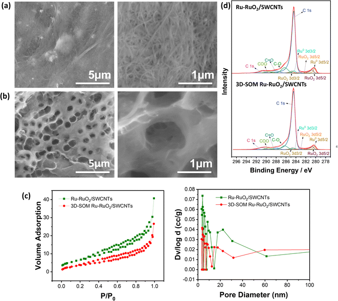
The top-view SEM images of mesoporous Ru–RuO2/SWCNTs (Fig. 1a) and 3D-SOM Ru–RuO2/SWCNTs (Fig. 1b) electrodes show different pore structures at different magnifications. The 3D-SOM Ru–RuO2/SWCNTs electrode has 1 μm-sized large pores interconnected with mesopores throughout the electrode that are created by the removal of SiO2 particles (Fig. 1b), while the conventional Ru–RuO2/SWCNTs electrode has only small pores derived from SWCNTs aggregation (Fig. 1a). The introduction of the interconnected macropores in the electrode leads to the decreased surface area of 3D-SOM Ru–RuO2/SWCNTs as measured by the N2 adsorption/desorption isotherm shown in Fig. 1c. Besides, the pore volume of 3D-SOM Ru–RuO2/SWCNTs also decreased because the BJH method used in the measurement cannot cover macropores (Fig. 1c). X-ray photoelectron spectroscopy (XPS) analysis was performed to investigate the chemical composition of the electrodes. In Fig. 1d, the higher peak intensities corresponding to Ru–RuO2 catalysts were observed in the Ru–RuO2/SWCNTs sample, which is consistent with thermal gravimetric analysis (TGA) results (Fig. S3†). In addition, the surface chemical compositions of Ru–RuO2/SWCNTs and 3D-SOM Ru–RuO2/SWCNTs electrodes are very similar to C 1s, C–O, C![[double bond, length as m-dash]](https://www.rsc.org/images/entities/char_e001.gif) O, COO from SWCNTs, F (F 1s spectra in Fig. S2c†) from PVdF binders, and Ru0 3d3/2, Ru0 3d5/2, RuO2 3d3/2, RuO2 3d5/2 from Ru–RuO2 decorated catalysts.
O, COO from SWCNTs, F (F 1s spectra in Fig. S2c†) from PVdF binders, and Ru0 3d3/2, Ru0 3d5/2, RuO2 3d3/2, RuO2 3d5/2 from Ru–RuO2 decorated catalysts.
More polymeric binders (12.5 wt%) resulted in the ordered microporous structure, as displayed in Fig. S4.† However, the small pores in this structure were already blocked by the polymers at the fresh condition (Fig. S4b†) and further blocked after the discharge process (Fig. S4c†). This observation is consistent with the pore size distribution results (see Fig. S4d and e, Table S1†) measured by Brunauer–Emmett–Teller (BET) isotherms. The air electrode with blocked small pores leads to higher LOB cell impedance (Fig. S4f†) and overpotential. Fig. S4g† shows the plot of the first charge–discharge voltage profiles of LOB cells with 3D-SOM Ru–RuO2/SWCNTs electrodes with either 6.25 wt% or 12.5 wt% of the PVDF binder. Thus, preserving mesopores are important with a proper amount of the polymeric binder to introduce the interconnected larger pore structure.
Before the long-term cycling of LOBs using a 3D-SOM air electrode, the anodes, and electrolytes were first optimized. In our recent work,4 we have developed a robust, solid electrolyte interphase (SEI) layer to protect the Li metal anode (LMA). This artificial SEI layer contains a polymer phase with stiff inorganic components, which was called the polymer-supported (PS)-SEI layer. The PS-SEI layer impedes the side reactions between the metallic Li anode and the mobile catalyst (i.e., redox mediator, RM), (2,2,6,6-tetramethylpiperidin-1-yl)oxyl (TEMPO) during the long-term LOB operation. A similar PS-SEI layer has been pre-formed on the surface of LMA for all the LOBs investigated in this work. In addition, electrolytes used in LOBs were optimized using conventional air electrodes consisting of SWCNTs coated on carbon paper (CP) with a gas diffusion layer (Sigracet 39BC, SGL Carbon) using polyvinylidene fluoride (PVDF) as a binder. It is found that the cells with an electrolyte containing lithium bis(trifluoromethanesulfonyl)imide (LiTFSI) salt exhibit lower impedance (see ESI Fig. S5†) and longer cycling life (91 vs. 54 cycles) (see Fig. S5b in ESI†) than those using lithium triflate (LiTf) salt in tetra(ethylene glycol) dimethyl ether (G4) solvent used in both electrolytes. The improved performance can be attributed to the higher ionic conductivity and lower donor number of the LiTFSI-containing electrolyte. The LiTFSI-containing electrolyte was further optimized using a dual catalyst (containing a mobile catalyst TEMPO added in the electrolyte and a solid catalyst added on the air electrode). The dual catalyst leads to lower cell impedance (see ESI Fig. S6a†) and smaller overvoltage during the pre-charging process (see ESI Fig. S6b†). It also leads to better cycling performance (see ESI Fig. S6c†).
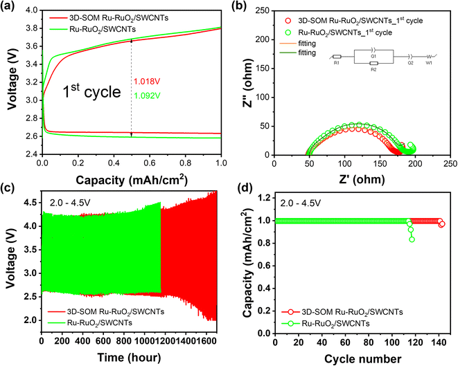
LOBs consisting of a 3D-SOM Ru/SWCNTs air electrode, a pre-treated LMA (with PS-SEI layer), and 1 M LiTFSI/G4 electrolyte, including 0.1 M TEMPO as a redox mediator, were cycled between 2.0 V and 4.5 V at 0.2 mA cm−2 in a pure O2 environment (see Experimental section in the ESI†). Fig. 2a and b compare the overpotential and impedance of the LOB cells using air electrodes with and without 3D-SOM structures when cycled between 2.0–4.5 V. After the cells were discharged to 2.0 V at a current density of 0.2 mA cm−2, the cell without semi-ordered macroporous structure (labeled as Ru–RuO2/SWCNTs) exhibits a larger cell overpotential (1.092 V) and resistance (187 ohms) than the cell with an ordered macroporous structure (labeled as 3D-SOM Ru–RuO2/SWCNTs) (1.018 V and 171 ohms) at the first cycle. For the LOB cell with the 3D-SOM Ru–RuO2/SWCNTs electrode, cycling stability increases to 140 cycles with relatively steady cell overpotentials compared to the LOB cell with the Ru–RuO2/SWCNTs electrode (115 cycles), as shown in Fig. 2c and d. This result demonstrates the importance of the 3D-SOM structure in the design of air electrodes, which can facilitate the effective diffusion of mobile molecules/ions in the electrolyte throughout the pore space during the discharge process. The cell assembled with Ru–RuO2/SWCNTs electrode prepared with a higher amount of polymeric binder (12.5 wt%), which totally blocked the small pores (Fig. S4a–c†) leading to higher LOB cell impedance and overpotential even at the initial cycles, as shown in Fig. S7.† This result also indicates the importance of maintaining open pores after the end of the discharge process.
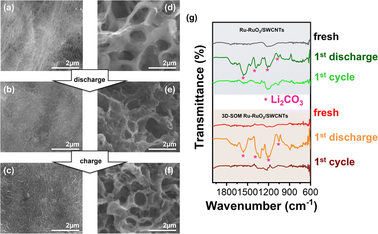
Postmortem analysis on the air electrodes retrieved from the cycled cells (disassembled in an argon-filled glovebox) was used to investigate the mechanism behind the improved performance of LOBs using the 3D-SOM Ru–RuO2/SWCNTs electrode. The SEM morphologies of the fresh, discharged (2 V), and charged (4.5 V) Ru–RuO2/SWCNTs electrodes are shown in Fig. 3a–c, respectively. The corresponding SEM images for 3D-SOM Ru–RuO2/SWCNTs electrode are shown in Fig. 3d–f. Images in Fig. 3b indicate that the Ru–RuO2/SWCNTs electrode surface without ordered structure was covered with a dense layer of discharge products after the 1st discharge. This result indicates that the mesoporous structures were blocked by the accumulated discharge products, although this electrode has a higher total surface area and pore volume (see Fig. 1c). In contrast, the 3D-SOM Ru–RuO2/SWCNTs electrode still maintained its macroporous structure even after it was discharged under the same ORR (see Fig. 3e). After the charging process (i.e., oxygen evolution reaction (OER)), the interconnected macroporous electrode with clean pore surfaces was almost recovered to its original structure, as shown in Fig. 3f. For each discharge and the following charge steps, attenuated total reflectance (ATR)-Fourier transform infrared spectroscopy (FTIR) analysis was carried out to confirm the formation and decomposition of the discharge products on two different electrodes (Fig. 3g) after the charge and discharge processes, respectively. Although the electrochemically-stable tetraglyme solvent was used in the LOB cells, the dominant discharge products are lithium carbonate (Li2CO3) accompanied by the electrolyte decomposition as revealed by FTIR and XPS measurements (Fig. 4f and g), as reported by Bruce and coworkers.41 After the 1st discharge, typical peaks corresponding to Li2CO3 appeared for both Ru–RuO2/SWCNTs and 3D-SOM Ru–RuO2/SWCNTs electrodes. After the following charge (at the end of the 1st full charge), the FTIR peaks (see Fig. 3d) related to the reaction products remaining in the non-3D-SOM electrode (or Ru–RuO2/SWCNTs) were larger than those of 3D-SOM-Ru–RuO2/SWCNTs electrode. This result indicates that the interconnected 3D-SOM structure enabled better transport of mobile molecules and ions in the electrolyte. Therefore, the discharge products accumulated in the air electrode can be charged more completely. This is consistent with the open pore structure of the 3D-SOM electrode, as shown on the right side of Fig. 3a–c.
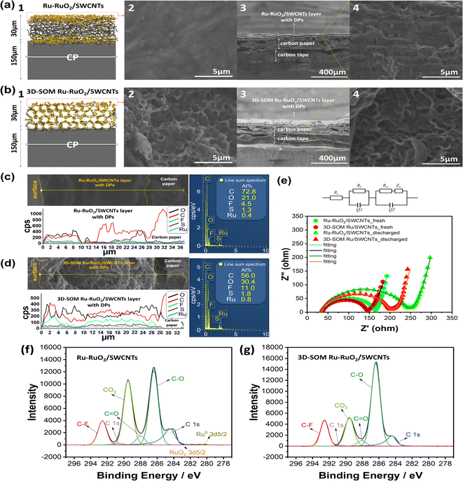
To investigate the distribution of the discharge products throughout the air electrodes, the electrode/electrolyte interface and its cross-sections were analyzed by scanning electron microscopy (SEM) and energy-dispersive X-ray spectroscopy (EDX). Fig. 4a1 is the schematic of the cross-section view along the Ru–RuO2/SWCNTs and CP interface. Fig. 4b1 is a similar view along the 3D-SOM Ru–RuO2/SWCNTs and CP interface.
After the 1st discharge, the Ru–RuO2/SWCNTs electrode is completely blocked, as shown in its top-view SEM image (Fig. 4a2), while the surface pores of the 3D-SOM Ru–RuO2/SWCNTs electrode were still well-maintained (Fig. 4b2) due to its good porosity and low tortuosity. Unlike its surfaces, the bulk phase of the Ru–RuO2/SWCNTs electrode was not totally filled with the discharge products, as shown in its cross-sectional SEM images (Fig. 4a3 and a4). In contrast, macroporous structures of the 3D-SOM Ru–RuO2/SWCNTs electrode were well maintained even after the discharge, as shown in Fig. 4b3 and b4. The EDX scan and TGA analysis were employed to quantify the elements in the samples. TGA curves in Fig. S3† demonstrate that the Ru–RuO2/SWCNTs electrode has more Ru–RuO2 catalysts than the 3D-SOM Ru–RuO2/SWCNTs electrode due to the larger pore volume and smaller surface area resulting from the 3D-SOM structure. Fig. 4c, d and S8† show the EDX line- and area-scan results for the surfaces and cross-sections of the electrode samples after the discharge process for Ru–RuO2/SWCNTs and 3D-SOM Ru–RuO2/SWCNTs electrodes. The Ru–RuO2 catalysts decorated on the SWCNTs were not observed by EDX as the discharge products were accumulated on the electrode surfaces. A higher O level was detected on the surface of the Ru–RuO2/SWCNTs electrode while less O level was detected from the cross-section area of the same sample than that on the 3D-SOM Ru–RuO2/SWCNT selectrode (Fig. S8†). XPS spectra of the O 1s from the sample surfaces (Fig. S8 e and f†) also revealed that the mesoporous Ru–RuO2/SWCNTs electrode had more discharge products on its surface than the corresponding surface of 3D-SOM Ru–RuO2/SWCNTs electrode. The result is consistent with the EDX line profile analysis shown in Fig. 4c and d. The O element (black line) across the 3D-SOM Ru–RuO2/SWCNTs electrode was evenly distributed from the electrode surface to the electrode/CP interface, while the O element was distributed nonuniformity across the Ru/SWNCTs electrode. Fig. 4f and g show the XPS spectra of the C 1s from the surfaces of the discharged air electrodes for non-3D-SOM and 3D-SOM structured electrodes, respectively. The results reveal that more discharge products (mainly Li2CO3) were deposited on the surface of the Ru–RuO2/SWCNTs electrode, however, some small peaks related to Ru–RuO2 catalysts were still detected even with the accumulated thick discharge-product layer (Fig. 4f). In contrast, the XPS spectra of 3D-SOM Ru–RuO2/SWCNTs did not show any peaks related to Ru–RuO2 catalysts on its surface, indicating the uniform formation of the discharge products with the 3D-SOM structure. This is a clear indication that reaction products blocked the surfaces of carbon paper where most ORR occurred. This will largely restrict the transport of O2 and Li ions in the electrolyte inside the bulk electrode.
Nyquist plots of the discharged LOB cells with Ru–RuO2/SWCNTs (green) and 3D-SOM Ru–RuO2/SWCNTs (red) electrodes show that the formation of the solid discharge products on the porous air electrode leads to an increase of Rct in the cells after the discharge process from the fresh cell (Fig. 4e). The effect of the 3D-SOM structure of the air electrode on the utilization of the pore structure is well demonstrated by the large differences on the charge transfer resistances between the discharged LOB cells with a Ru–RuO2/SWCNTs electrode and a 3D-SOM Ru–RuO2/SWCNTs electrode. Once the surface mesopores are clogged with the discharge products, most inside pores cannot be fully utilized because of the slow diffusion of mobile components under the capacity-limited testing protocol. Therefore, the 3D-SOM structured air electrode can maintain its macroporous structure throughout the air electrode during the discharge process, as illustrated schematically in the ESI in Fig. S9.†
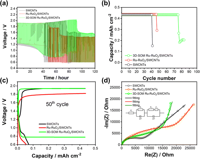
In consideration of the advantages of 3D-SOM structured air electrodes in non-aqueous LOBs, the same 3D-SOM Ru–RuO2/SWCNTs electrodes were also investigated in aqueous ZOBs. Coin cells were assembled using a carbon-based air cathode, Zn anode, glass fiber separator, 3D-Ni foam (as the anode current collector), and aqueous electrolyte of KOH with Zn acetate and tested in Teflon air containers, as shown in the ESI Fig. S10.† Three different carbon materials with different pore structures were tested as air electrodes with other same cell components and under the same testing conditions (ESI Fig. S11†). The assembled cells demonstrated much better stability (41 cycles) with SWCNTs air electrode than the cells with CP and carbon cloth electrodes tested within a cut-off voltage range of 0.6–2.0 V at a current density of 1 mA cm−2 (30 min charge and discharge) (ESI Fig. S12a and S12b†). This result means that the pore structure of the air electrode is a key factor for the reversibility of OER/ORR during the ZOB cell operation in the aqueous electrolyte. The effect of 3D-SOM Ru–RuO2/SWCNTs electrode was further investigated by comparing the SEM images of the pristine SWCNT and Ru–RuO2/SWCNTs electrodes, all having different pore structures as displayed in the ESI, Fig. S13.† The voltage profiles of the ZOB cell with a 3D-SOM Ru–RuO2/SWCNTs electrode remained stable even after 50 h (50 cycles) to 75 h (75 cycles), while a sudden increase in the cell overpotentials limits the cycle life of the cells to only 40th and 46th, for the cells with SWCNTs and the Ru–RuO2/SWCNTs electrodes, respectively (see Fig. 5a–c, and ESI Fig. S14†). Fig. 5d shows the impedance of the cells during EIS measurement after the cell failures. The Warburg impedances in the Nyquist plots reveal that the better reversibility of the electrochemical reactions with a 3D-SOM Ru–RuO2/SWCNTs air electrode is closely related to the better mass transportation of ions species and O2 molecules in the aqueous electrolyte.
In summary, the 3D-SOM Ru–RuO2/SWCNTs membrane was experimentally verified as an effective air electrode for the long-term cycling of non-aqueous LOBs and aqueous ZOBs. This new air electrode structure can facilitate the smooth flow of electrolyte and active species, including oxygen and ion species during the charge/discharge process of MOBs and largely alleviate detrimental effects due to the accumulation of the reaction product during the discharge process. Therefore, the 3D-SOM structured air electrode can be used as an effective approach to facilitate better utilization of the air electrode to form uniform discharge products, reducing the cell overpotential and impedance of MOBs, enhancing their capacity, and extending their cycle life.
Author contributions
J.-G. Zhang and W. Xu proposed the research concept. H.-S. Lim designed detailed experimental procedures and performed the material preparation, battery test, and data analysis. W. J. Kwak designed the battery testing protocols. D. T. Nguyen performed XPS measurement and data processing. W. Wang contributed to the discussion on the zinc–oxygen battery test. H.-S. Lim, W. Xu, and J.-G. Zhang prepared the manuscript with input from all other co-authors.Conflicts of interest
The authors declare no conflicts of interest.Acknowledgements
The work on lithium–oxygen batteries was supported by the Assistant Secretary for Energy Efficiency and Renewable Energy, Vehicle Technologies Office, Advanced Battery Materials Research program of the U.S. Department of Energy (DOE) under Contract No. DE-AC05-76RL01830. The work on zinc–oxygen batteries was supported by the Pacific Northwest National Laboratory (PNNL) Energy Storage Materials Initiative (ESMI). The microscopic characterizations were conducted in the William R. Wiley Environmental Molecular Sciences Laboratory (EMSL), a National Scientific User Facility located at PNNL, which is sponsored by DOE's Office of Biological and Environmental Research. PNNL is operated by Battelle for DOE under Contract DE-AC05-76RL01830.References
- K. M. Abraham and Z. Jiang, J. Electrochem. Soc., 1996, 143, 1–5 CrossRef CAS.
- W.-J. Kwak, H.-S. Lim, P. Gao, R. Feng, S. Chae, L. Zhong, J. Read, M. H. Engelhard, W. Xu and J.-G. Zhang, Adv. Funct. Mater., 2021, 31, 2002927 CrossRef CAS.
- W.-J. Kwak, Rosy, D. Sharon, C. Xia, H. Kim, L. R. Johnson, P. G. Bruce, L. F. Nazar, Y.-K. Sun, A. A. Frimer, M. Noked, S. A. Freunberger and D. Aurbach, Chem. Rev., 2020, 120, 6626–6683 CrossRef CAS PubMed.
- H.-S. Lim, W.-J. Kwak, S. Chae, S. Wi, L. Li, J. Hu, J. Tao, C. Wang, W. Xu and J.-G. Zhang, ACS Energy Lett., 2021, 6, 3321–3331 CrossRef CAS.
- Y. Wang, N.-C. Lai, Y.-R. Lu, Y. Zhou, C.-L. Dong and Y.-C. Lu, Joule, 2018, 2, 2364–2380 CrossRef CAS.
- S. Ding, X. Yu, Z.-F. Ma and X. Yuan, J. Mater. Chem. A, 2021, 9, 8160–8194 RSC.
- M. A. Rahman, X. Wang and C. Wen, J. Electrochem. Soc., 2013, 160, A1759–A1771 CrossRef CAS.
- M. T. Tsehaye, F. Alloin, C. Iojoiu, R. A. Tufa, D. Aili, P. Fischer and S. Velizarov, J. Power Sources, 2020, 475, 228689 CrossRef CAS.
- J. Pan, Y. Y. Xu, H. Yang, Z. Dong, H. Liu and B. Y. Xia, Adv. Sci., 2018, 5, 1700691 CrossRef PubMed.
- P. Chen, K. Zhang, D. Tang, W. Liu, F. Meng, Q. Huang and J. Liu, Front. Chem., 2020, 8, 372 CrossRef CAS PubMed.
- N. Imanishi and O. Yamamoto, Mater. Today Adv., 2019, 4, 100031 CrossRef.
- C. Wang, Z. Xie and Z. Zhou, APL Mater., 2019, 7, 040701 CrossRef.
- J. Zhang, Y. Zhao, B. Sun, Y. Xie, A. Tkacheva, F. Qiu, P. He, H. Zhou, K. Yan, X. Guo, S. Wang, A. M. McDonagh, Z. Peng, J. Lu and G. Wang, Sci. Adv., 2022, 8, eabm1899 CrossRef PubMed.
- H. Wang, J. Li, F. Li, D. Guan, X. Wang, W. Su and J. Xu, Chem. Res. Chin. Univ., 2021, 37, 232–245 CrossRef CAS.
- S. Wu, J. Tang, F. Li, X. Liu and H. Zhou, Chem. Commun., 2015, 51, 16860–16863 RSC.
- L. Wang, Y. Zhang, Z. Liu, L. Guo and Z. Peng, Green Energy Environ., 2017, 2, 186–203 CrossRef.
- J. Lu, Y. Lei, K. C. Lau, X. Luo, P. Du, J. Wen, R. S. Assary, U. Das, D. J. Miller, J. W. Elam, H. M. Albishri, D. A. El-Hady, Y. K. Sun, L. A. Curtiss and K. Amine, Nat. Commun., 2013, 4, 2383 CrossRef PubMed.
- J. Fu, X. Guo, H. Huo, Y. Chen and T. Zhang, ACS Appl. Mater. Interfaces, 2019, 11, 14803–14809 CrossRef CAS PubMed.
- G. Huang, J. Wang and X. Zhang, ACS Cent. Sci., 2020, 6, 2136–2148 CrossRef CAS PubMed.
- J.-J. Xu, Z.-L. Wang, D. Xu, L.-L. Zhang and X.-B. Zhang, Nat. Commun., 2013, 4, 2438 CrossRef PubMed.
- L.-N. Song, W. Zhang, Y. Wang, X. Ge, L.-C. Zou, H.-F. Wang, X.-X. Wang, Q.-C. Liu, F. Li and J.-J. Xu, Nat. Commun., 2020, 11, 2191 CrossRef CAS PubMed.
- B. Liu, J. Yang, H. Duan, X. Liu and J. Shui, ACS Appl. Mater. Interfaces, 2019, 11, 35264–35269 CrossRef CAS PubMed.
- H. Yadegari, Q. Sun and X. Sun, Adv. Mater., 2016, 28, 7065–7093 CrossRef CAS PubMed.
- X. Luo, R. Amine, K. C. Lau, J. Lu, C. Zhan, L. A. Curtiss, S. Al Hallaj, B. P. Chaplin and K. Amine, Nano Res., 2017, 10, 4327–4336 CrossRef CAS.
- Y. Shen, D. Sun, L. Yu, W. Zhang, Y. Shang, H. Tang, J. wu, A. Cao and Y. Huang, Carbon, 2013, 62, 288–295 CrossRef CAS.
- Z. Wen, C. Shen and Y. Lu, ChemPlusChem, 2015, 80, 270–287 CrossRef CAS.
- D. Mao, Z. He, W. Lu and Q. Zhu, Nanomaterials, 2022, 12, 2063 CrossRef CAS PubMed.
- S. R. Younesi, S. Urbonaite, F. Björefors and K. Edström, J. Power Sources, 2011, 196, 9835–9838 CrossRef CAS.
- C. Tran, X.-Q. Yang and D. Qu, J. Power Sources, 2010, 195, 2057–2063 CrossRef CAS.
- N. Ding, S. W. Chien, T. S. A. Hor, R. Lum, Y. Zong and Z. Liu, J. Mater. Chem. A, 2014, 2, 12433–12441 RSC.
- X. Li, J. Electrochem. Soc., 2015, 162, A1636–A1645 CrossRef CAS.
- N. Mahne, O. Fontaine, M. O. Thotiyl, M. Wilkening and S. A. Freunberger, Chem. Sci., 2017, 8, 6716–6729 RSC.
- V. Viswanathan, K. S. Thygesen, J. S. Hummelshøj, J. K. Nørskov, G. Girishkumar, B. D. McCloskey and A. C. Luntz, J. Chem. Phys., 2011, 135, 214704 CrossRef CAS PubMed.
- A. C. Luntz, V. Viswanathan, J. Voss, J. B. Varley, J. K. Nørskov, R. Scheffler and A. Speidel, J. Phys. Chem. Lett., 2013, 4, 3494–3499 CrossRef CAS.
- K. B. Knudsen, T. Vegge, B. D. McCloskey and J. Hjelm, J. Electrochem. Soc., 2016, 163, A2065–A2071 CrossRef CAS.
- J.-J. Xu, Z.-L. Wang, D. Xu, F.-Z. Meng and X.-B. Zhang, Energy Environ. Sci., 2014, 7, 2213 RSC.
- P. Li, W. Sun, Q. Yu, M. Guan, J. Qiao, Z. Wang, D. Rooney and K. Sun, Mater. Lett., 2015, 158, 84–87 CrossRef CAS.
- C. Li, Z. Guo, Y. Pang, Y. Sun, X. Su, Y. Wang and Y. Xia, ACS Appl. Mater. Interfaces, 2016, 8, 31638–31645 CrossRef CAS PubMed.
- J. G. Kim, Y. Noh, Y. Kim, S. Leed and W. B. Kim, Nanoscale, 2017, 9, 5119 RSC.
- Y. Song, Y. Li, Y. Peng, C. Zhang and F. Yin, Microporous Mesoporous Mater., 2021, 314, 110866 CrossRef CAS.
- S. A. Freunberger, Y. Chen, N. E. Drewett, L. J. Hardwick, F. Barde and P. G. Bruce, Angew. Chem., Int. Ed., 2011, 50, 8609–8613 CrossRef CAS PubMed.
Footnotes |
| † Electronic supplementary information (ESI) available. See DOI: https://doi.org/10.1039/d2ta09442h |
| ‡ Current address: Department of Chemistry, Ajou University, Suwon, 16499, Republic of Korea. |
| This journal is © The Royal Society of Chemistry 2023 |

