DOI:
10.1039/D2TC04441B
(Review Article)
J. Mater. Chem. C, 2023,
11, 7885-7919
Phthalocyanines, porphyrins and other porphyrinoids as components of perovskite solar cells
Received
19th October 2022
, Accepted 18th December 2022
First published on 9th January 2023
Abstract
Perovskite-based solar cells (PSCs) are third-generation devices that are reluctant to leave the laboratory to reach the market due to their limitations, such as their sensitivity to humidity, heat and light. Thus, there is a large volume of research to develop materials and manufacturing methods that make such a step possible. Phthalocyanines (Pcs) and porphyrins (Pors) constitute two families of molecules that have been showing a real utility in improving these devices in terms of efficiency and stability, therefore, a multitude of scientific works focused on this sense can be found. This is because, together with their outstanding and tunable optoelectronic properties, they are stable materials against the elements. In addition, they could be obtained industrially at low cost and applied on a large scale using techniques such as roll-to-roll. The best works from 2019 to 2022 on Pcs, Pors and other porphyrinoids applied in PSCs are here reviewed. We attempt to relate the molecular structure with the performances obtained when applied in certain roles to guide the design of improved structures, maybe capable of pushing this experimental technology to an industrial level.

Desiré Molina
| Desiré Molina is assistant professor of Organic Chemistry at Universidad Miguel Hernández de Elche. She received her PhD degree from Universidad Miguel Hernández de Elche in 2016, under the guidance of Prof. Ángela Sastre-Santos, where she has remained so far. She also joined the group of Prof. Anders Hagfeldt at EPFL (Switzerland) for 12 months as a postdoctoral fellow. Her research interests concern in the development of new materials for their application in photovoltaic technologies and other electrical devices. |

Jorge Follana-Berná
| Jorge Follana-Berná is assistant professor of Organic Chemistry at Universidad Miguel Hernández de Elche. He studied chemistry at Universidad de Alicante and then he moved to Universidad Miguel Hernández de Elche where he received his PhD degree in 2020, under the guidance of Prof. Ángela Sastre-Santos. His research is focused on synthesis and characterization of phthalocyanines for their application as photosensitizers in photovoltaic devices, catalysis, and photodynamic therapy (PDT). |

Ángela Sastre-Santos
| Ángela Sastre-Santos is Full Professor of Organic Chemistry (2010) and Director of the Instituto de Bioingeniería at the Universidad Miguel Hernández de Elche (2019, Spain). She studied chemistry at the Universidad Autónoma de Madrid, where she obtained her PhD (1995, Tomás Torres). She was Postdoctoral fellow at the École Supérieure de Physique et Chimie Industrielles (Paris, Jacques Simon) and at the University of California, Santa Barbara and Los Angeles (Fred Wudl). She moved in 1998 to the UMH. Her research interest focuses on the synthesis of molecular and supramolecular electroactive systems with nano- and biotechnological applications. |
10th anniversary statement
We would like to congratulate Journal of Materials Chemistry for the 10th anniversary and will like to thank the journal for let us publish four different reviews and two full articles during this decade. We are organic chemists working in the synthesis of different materials as phthalocyanines, perylenediimides and diketopyrrolopyrroles, among others, for applications as components in solar cells and J. Mater. Chem. has help us a lot to disseminate our work with different reviews where our molecules were components in dye sensitized solar cells, bulk heterojunction solar cells, and as single molecules in photovoltaic technologies. This review highlights the importance of the phthalocyanines, porphyrins and other porphyrinoids as components of perovskite solar cells acting as hole transporting materials, additives, and interlayers. Our contribution in this field is quite active and it has been published in J. Mater. Chem. C, 2022, 10, 11975–11982 (10.1039/D2TC01187E) in a full paper where the different diethynyl-conjugated zinc–phthalocyanine dimers were incorporated in perovskite solar cells as hole-transporting materials for improved stability. Our future directions are going in the search of new materials improving their semiconductor capabilities as well as their self-assembly organization that could help to a better performance in the photovoltaic devices.
|
1. Introduction
Among the emerging photovoltaic (PV) technologies, perovskite solar cells (PSCs) stand out for the high performance they offer. Indeed, PSCs have revolutionized the research of PV technologies in a few years, from 3% efficiency in 20091 to more than 25.5% efficiency at the moment.2,3 This great development is not only due to the exceptional optoelectronic properties of perovskites, such as high absorption coefficients,4 low recombination ratio,5 high charge mobility,6 as well as a tunable band gap,7 but also because perovskite are low-cost materials8 that can be easily processed from solution and can even be applied in flexible devices (Fig. 1).9,10
 |
| | Fig. 1 (a) Representation of the perovskite crystalline structure; (b) a 3D or mesoporous n–i–p architecture PSC; (c) a planar n–i–p architecture PSC; and (d) a planar p–i–n PSC. | |
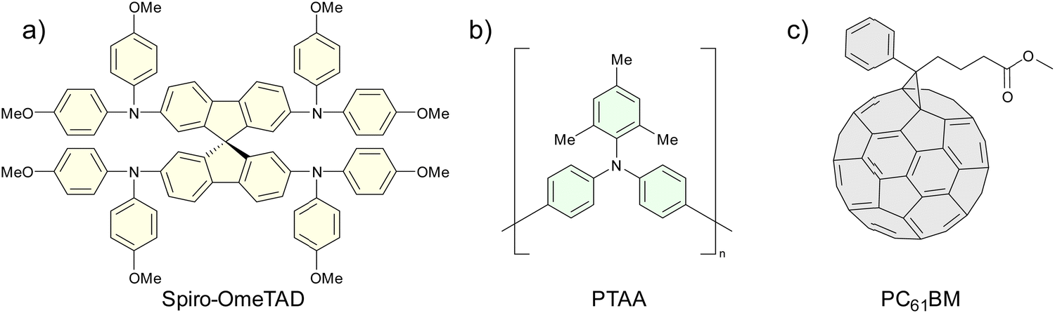
The main challenge regarding PSCs to reach the market is the loss of efficiency since it decreases under heat and light soaking due to ionic migration and segregation,11 and because perovskite is very unstable against humidity due to its ionic nature.12 In short, PSCs are not stable enough to rival the solar panels that dominate the market. In this sense, the layers that are in contact with the perovskite layer play a crucial role, since the correct choice of materials as well as their correct deposition determine the performance of the PV devices, including long-term stability. These layers generally are the hole transporting layer (HTL) and the electron transporting layer (ETL). Thus, it is very important that these materials conduct the corresponding charges efficiently while at the same time insulating the active layer from moisture. Archetypal hole-transporting materials (HTM) in n–i–p devices are the single molecule 2,20,7,-70-tetrakis(N,N-di-p-methoxyphenylamine)-9,90-spirobifluorene (spiro-OMeTAD) and the polymer poly(triarylamine) (PTAA) (Fig. 2a and b), both p-type organic semiconductors. Although these materials are widely and successfully used at an experimental level, the truth is that they are too expensive to be profitable at an industrial level. Furthermore, the need to add hydrophilic dopants-such as 4-tert-butylpyridine (tBP) and the salt lithium bis(trifluoromethanesulfonyl)imide (Li-TFSI)- to improve its performance generates stability issues.13 On the other hand, archetypal ETLs are fullerene derivatives, such as PC61BM (Fig. 2c). Fullerenes are n-type semiconductors that are often weakly coordinated with the perovskite layer, which limits the performance of the devices.14 Because of these limitations, a wide range of organic semiconductors are being investigated both as HTM and ETL.15–17
 |
| | Fig. 2 Chemical structures of (a) spiro-OMeTAD, (b) PTAA, and (c) PC61BM. | |
Macrocyclic porphyrinoids, such as phthalocyanines (Pcs), porphyrins (Pors) and other macrocyclic compounds based on Pors, are a set of interesting materials to be applied in PSCs. These compounds are thermally and photochemically stable, with remarkable optoelectronic properties, for instance, an intense absorption in the visible and near infrared region. Besides, their chemical versatility allows such properties to be modulated by changing the central metal, the substituents in different positions and varying the degree of molecular symmetry. In view of such properties, it is not surprising that these materials are used in various types of applications, from pigments for their robustness and intense colors, going through sensors,18 in photodynamic therapy against cancer (PDT),19 as catalysts,20 to active materials in organic and dye-sensitized PV cells (OSCs and DSSCs).21–23 Furthermore, Pcs, Pors and other porphyrinoids are real candidates to be part of PSCs when they reach the industrial level. Indeed, they have hitherto been applied in PSCs at an experimental level in various roles with promising results.15,24
In this review article, the most significant works on porphyrinoids in PSCs from 2019 to the present along with the current records will be exposed and analyzed. From the point of view of molecular structure, we will try to establish what central metal, and what substituents are the most appropriate to obtain the best performance, and we will compare phthalocyanines and porphyrins in terms of efficiency and stability.
2. Phthalocyanines in perovskite solar cells
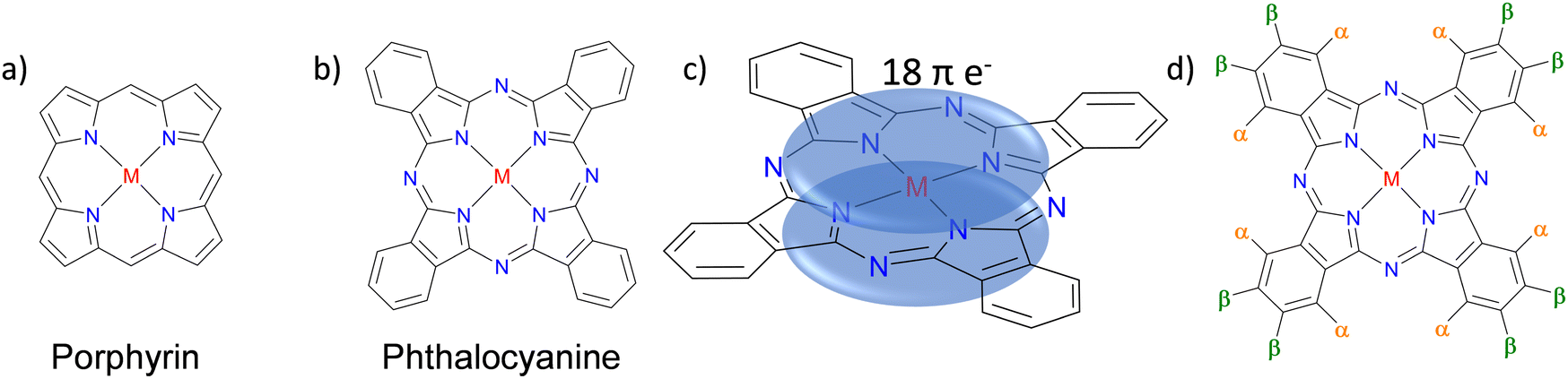
Pcs are macrocycles analogs to Pors with 18-π electrons in their central ring (Fig. 3b–d).
 |
| | Fig. 3 Chemical structure of (a) an unsubstituted porphyrin, (b) an unsubstituted phthalocyanine, (c) representation of π-clouds in the phthalocyanine macrocycle, and (d) a phthalocyanine with the indicated peripheral (β) and non-peripheral (α) positions. M = H2 or a metal. | |
A Pc can be metal-free (H2Pc) or metallated (MPc), being able to complex a wide variety of metal ions such as Cu, Zn, Mn, Mg, Ti, Fe, Co and Ni. Substituents can be introduced in the α (non-peripheral) and/or β (peripheral) positions (Fig. 3d) to modify properties such as solubility; the aggregation in the solid state, and thus control the morphology of the layers; the optoelectronic properties, depending on the electronic nature of such substituents. Based on the substituents, Pcs can be classified according to whether they are in peripheral or non-peripheral positions, or there are no substituents at all and according to the functional group in question, so alkyl-Pcs, amino-Pcs, alkoxy-Pcs, thioalkyl-Pcs, etc., can be found.
The works on Pcs as HTMs that provide a PCE higher than 14% in PSCs are discussed below, being the most abundant literature; then most important contributions dedicated to Pcs as additives in the active layer will be shown; to continue, the results of de Pcs as passivating agents and as interlayers will be presented; and finally, we will talk about the Pcs in other roles within the PSCs devices.
2.1. Phthalocyanines as HTM in n–i–p PSCs
Pcs are good alternatives to spiro-OMeTAD and PTAA for their application as HTM in PSCs. Indeed, the works to be exhibited here show that Pcs can offer better performance than commonly used materials, both from the point of view of costs, efficiency and/or stability. Given the volume of publications found in the last four years and to give coherence to the discussion, the Pc-based HTMs applied in n–i–p PSCs are classified according to the in non-substituted, alkyl/aryl-substituted (β-substitute, α-substituted and dimers), amino-substituted and alkoxy/phenoxy-substituted.
2.1.1. Non-substituted Pcs.
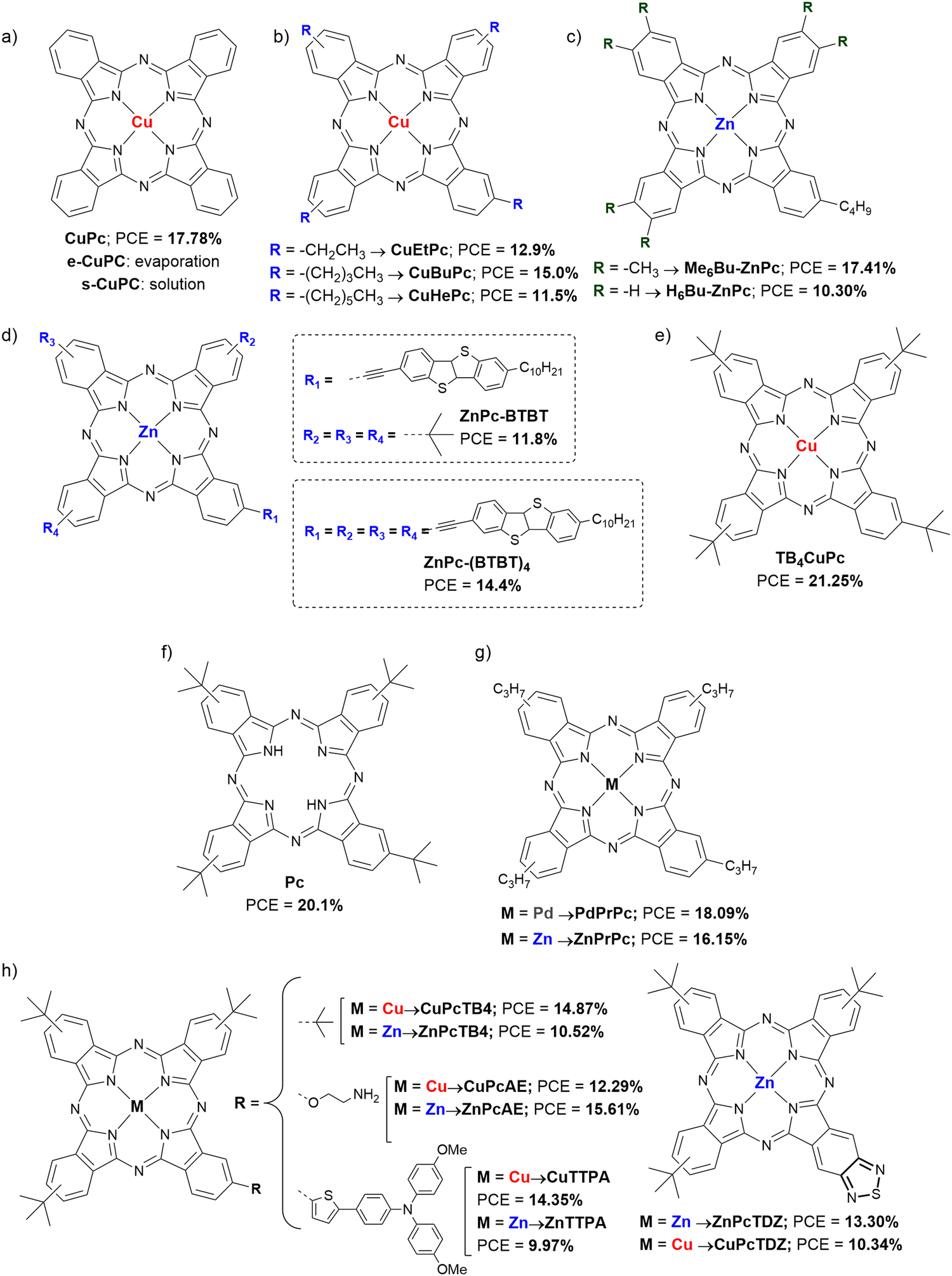
This type of Pc is characterized by its low solubility in common organic solvents, that is why vacuum evaporation is frequently used as a deposition method. Liao's group published in 2019 an article in which they used vacuum deposited CuPc (Fig. 4a and Table 1) as HTM in planar devices, where the typical gold electrode was replaced by a carbon electrode deposited by the doctor blade method. The work is focused on studying if the doping with zinc (2 mM) of the ETL made of SnO2 gives rise to better performance than the ETL without doping. The champion device yielded a power conversion efficiency (PCE) of 17.78%. Furthermore, the authors state that both the carbon electrode and the CuPc HTL contribute to excellent long-term stability of the devices, stored in ambient air with a humidity ≈20% without encapsulation, and virtually retaining 100% of starting PCE. This was supported by showing the hydrophobicity of the CuPc layer with a contact angle with a water droplet of 84°, combined with the carbon electrode hydrophobicity, whose contact angle was 111.7°.25CuPc (Fig. 4a and Table 1) was also applied as dopant-free HTM by Kam et al. in all-vacuum sequential deposition planar devices in 2019. The work focused on showing a simple and economical method of manufacturing PSCs by depositing all the layers that make up the device under high vacuum. The authors chose CuPc because of its low cost and chemical and thermal stability. Devices containing CuPc as HTM yielded a PCE of 15.14%, and a superior stability to that of the reference HTM, showed that it is a fabricating method to be considered.26
 |
| | Fig. 4 Chemical structures of (a) non-substituted CuPc, (b) β-alkylCuPcs, (c) β-alkylZnPcs, (d) ZnPc-BTBT derivatives, (e) TB4CuPc, (f) H2Pc, (g) PdPrPc and ZnPrPc, and (h) symmetrically and asymmetrically substituted CuPcs and ZnPcs applied as HTM in n–i–p PSCs. | |
Table 1 Hole mobilities and HOMO levels of different unsubstituted and alkyl/aryl-substituted Pcs used as HTMs in n–i–p PSCs, along with perovskite composition, device configuration and performances under reverse scan of the best devices
| HTMa |
μ
h (cm2 V−1 s−1) |
HOMO (eV) |
Perovskiteb |
Dopant |
Architecture |
Thickness |
−Jsc (mA cm−2) |
V
oc (V) |
FF (%) |
PCE (%) |
Ref. |
|
The names of the HTMs are the same as in the original publications.
MA is methylammonium ([CH3NH3]+), FA is formamidinium ([CN2H5]+).
c is compact layer and m means mesoporous layer.
The value of x is not clarified in the original work. — = not provided.
|
|
CuPc
|
10−3 to 10−2![[thin space (1/6-em)]](https://www.rsc.org/images/entities/char_2009.gif) 40–43 40–43 |
−5.2 |
Cs0.05(MA0.16FA0.84)0.95Pb(I0.84Br0.16)3 |
No |
Zn:SnO2/Perovs./Pc/Carbon |
30 nm |
23.4 |
1.098 |
69.2 |
17.78 |
25
|
|
CuPc
|
10−3 to 10−240–43 |
— |
MA0.56FA0.44Pb(I0.89Br0.11)3 |
No |
FTO/SnO2/Perovs./Pc/Au |
— |
19.16 |
1.02 |
77.3 |
15.14 |
26
|
|
CuEtPc
|
20.4 × 10⁻⁴ |
−5.16 |
MAPbI3 |
No |
FTO/SnO2/Perovs./Pc/Au |
60 nm |
20.4 |
0.95 |
66.6 |
12.9 |
27
|
|
CuBuPc
|
12.6 × 10⁻⁴ |
−5.14 |
MAPbI3 |
No |
FTO/SnO2/Perovs./Pc/Au |
60 nm |
21.0 |
1.02 |
70.0 |
15.0 |
27
|
|
CuHePc
|
8.77 × 10⁻⁴ |
−5.11 |
MAPbI3 |
No |
FTO/SnO2/Perovs./Pc/Au |
60 nm |
17.4 |
0.97 |
68.1 |
11.5 |
27
|
|
Me6Bu-ZnPc
|
6.85 × 10⁻⁴ |
−4.96 |
Cs0.05(MA0.13FA0.87)0.95Pb(I0.87Br0.13)3 |
No |
FTO/SnO2/Perovs./Pc/Au |
60 nm |
23.09 |
1.09 |
69.18 |
17.41 |
28
|
|
H6Bu-ZnPc
|
8.63 × 10⁻⁵ |
−4.98 |
Cs0.05(MA0.13FA0.87)0.95Pb(I0.87Br0.13)3 |
No |
FTO/SnO2/Perovs./Pc/Au |
60 nm |
21.32 |
1.06 |
45.58 |
10.30 |
28
|
|
ZnPc-BTBT
|
— |
−5.49 |
Csx(MA0.17FA0.83)(1–x)Pb(I0.83Br0.17)3 |
No |
FTO/c-TiO2/m-TiO2/Perovs./Pc/Auc |
— |
21.5 |
0.97 |
61.5 |
11.8 |
29
|
|
ZnPc-(BTBT)4
|
— |
−5.50 |
Csx(MA0.17FA0.83)(1–x)Pb(I0.83Br0.17)3 |
Li-TFSI/tBP |
FTO/c-TiO2/m-TiO2/Perovs./Pc/Auc |
— |
22.4 |
0.99 |
65.9 |
14.4 |
29
|
|
Pc
|
4.66 × 10⁻⁴ |
−5.0 |
Cs0.10FA0.75MA0.15Pb(I0.85Br0.15)3 |
Li-TFSI/tBP |
FTO/c-TiO2/m-TiO2/Perovs./Pc/Auc |
— |
22.7 |
1.10 |
80.7 |
20.1 |
30
|
|
PdPrPc
|
1.057 × 10⁻³ |
−4.90 |
Cs0.05(MA0.13FA0.87)0.95Pb(I0.87Br0.13)3 |
No |
FTO/SnO2/Perovs./Pc/Au |
— |
23.81 |
1.09 |
71.04 |
18.09 |
31
|
|
CuPcTB4
|
— |
−5.01 |
FA1−yMAyPbI3−xBrxd |
No |
FTO/c-TiO2/m-TiO2/Perovs./Pc/Auc |
— |
21.29 |
1.0449 |
66.9 |
14.87 |
32
|
|
CuPcAE
|
— |
−4.96 |
FA1−yMAyPbI3−xBrxd |
No |
FTO/c-TiO2/m-TiO2/Perovs./Pc/Auc |
— |
22.66 |
0.9157 |
59.2 |
12.29 |
32
|
|
CuPcTDZ
|
— |
−5.04 |
FA1−yMAyPbI3−xBrxd |
No |
FTO/c-TiO2/m-TiO2/Perovs./Pc/Auc |
— |
22.32 |
0.9252 |
50.1 |
10.34 |
32
|
|
CuPcTTPA
|
— |
−5.08 |
FA1−yMAyPbI3−xBrxd |
No |
FTO/c-TiO2/m-TiO2/Perovs./Pc/Auc |
— |
21.14 |
1.0288 |
66.0 |
14.35 |
32
|
|
CuPc
|
— |
— |
(FAPbI3)0.95(MAPbBr3)0.05 |
Li-TFSI/tBP |
FTO/c-TiO2/m-TiO2/Perovs./PMMA/Pc/Auc |
— |
24.87 |
1.08 |
79.29 |
21.25 |
34
|
|
N-CuMe2Pc/P3HTa |
3.84 × 10⁻³ |
−4.96 |
MAPbI3 |
No |
FTO/SnO2/Perovs./Pc/Au |
60 nm |
22.44 |
1.008 |
73.43 |
16.61 |
35
|
|
NiEt2Pc
|
1.33 × 10⁻⁵ |
−5.30 |
MAPbI3 |
No |
FTO/SnO2/Perovs./Pc/Au |
60 nm |
18.65 |
0.96 |
48.32 |
8.63 |
36
|
|
NiPr2Pc
|
3.64 × 10⁻⁴ |
−5.11 |
MAPbI3 |
No |
FTO/SnO2/Perovs./Pc/Au |
60 nm |
22.83 |
1.04 |
59.40 |
14.07 |
36
|
|
ZnPc-p-ZnPc 1
|
— |
−4.90 |
Cs0.05[(FA0.9MA0.1)Pb(I0.9Br0.1)3]0.95 + (PbI2)0.03 |
Li-TFSI/tBP |
FTO/c-TiO2/m-TiO2/Perovs./Pc/Auc |
— |
23.4 |
0.95 |
67.9 |
15.2 |
37
|
|
|
1.0 × 10⁻⁷ |
−4.90 |
Cs0.05(FA0.83MA0.17)0.95Pb(I0.83Br0.17)3 |
No |
FTO/c-TiO2/m-TiO2/Perovs./Pc/Auc |
20 nm |
21.3 |
1.06 |
69.1 |
15.7 |
38
|
|
ZnPc-th-ZnPc 1
|
2.8 × 10⁻⁷ |
−4.93 |
Cs0.05(FA0.83MA0.17)0.95Pb(I0.83Br0.17)3 |
No |
FTO/c-TiO2/m-TiO2/Perovs./Pc/Auc |
20 nm |
21.6 |
1.08 |
67.6 |
15.5 |
38
|
|
ZnPc-flu-ZnPc 2
|
1.1 × 10⁻⁷ |
−5.11 |
Cs0.05(FA0.83MA0.17)0.95Pb(I0.83Br0.17)3 |
No |
FTO/c-TiO2/m-TiO2/Perovs./Pc/Auc |
15 nm |
21.6 |
1.09 |
66.1 |
15.6 |
38
|
|
ZnPc-DPP-ZnPc 3
|
1.2 × 10⁻⁷ |
−4.90 |
Cs0.05(FA0.83MA0.17)0.95Pb(I0.83Br0.17)3 |
No |
FTO/c-TiO2/m-TiO2/Perovs./Pc/Auc |
20 nm |
20.6 |
1.10 |
73.8 |
16.8 |
38
|
|
TB4-ZnPc
|
0.97 × 10−432 |
−5.05 |
Cs0.05(FA0.83MA0.17)0.95Pb(I0.83Br0.17)3 |
No |
FTO/c-TiO2/m-TiO2/Perovs./Pc/Auc |
20 nm |
22.4 |
1.10 |
68.5 |
16.6 |
38
|
|
ZnPc-t-DPP-t-ZnPc 1
|
2.83 × 10⁻⁵ |
−4.89 |
(MAPbBr3)0.15(FAPbI3)0.85 |
Li-TFSI/tBP |
FTO/c-TiO2/m-TiO2/Perovs./Pc/Auc |
|
23.21 |
1.030 |
68.93 |
16.49 |
39
|
|
ZnPc-t-t-ZnPc 2
|
1.5 × 10⁻⁵ |
−5.00 |
(MAPbBr3)0.15(FAPbI3)0.85 |
Li-TFSI/tBP |
FTO/c-TiO2/m-TiO2/Perovs./Pc/Auc |
|
22.25 |
1.041 |
55.30 |
12.82 |
39
|
|
ZnPc-t-Spiro-t-ZnPc 3
|
4.08 × 10⁻⁵ |
−4.87 |
(MAPbBr3)0.15(FAPbI3)0.85 |
Li-TFSI/tBP |
FTO/c-TiO2/m-TiO2/Perovs./Pc/Auc |
|
23.63 |
1.039 |
74.62 |
18.32 |
39
|
2.1.2. Alkyl/aryl-substituted Pcs.
This group is very broad and includes both monomeric and dimeric Pcs whose principal substituents are alkyl and aryl groups. In order to make reading less dense, the works analyzed in this section are presented in three subsections: β-alkyl/aryl-substituted Pcs, α-alkyl/aryl-substituted Pcs and dimers of alkyl/aryl-substituted Pcs.
2.1.2.1. β-Alkyl/aryl-substituted Pcs.
In 2019, Feng et al. presented 3 low symmetrical CuPcs with different peripheral alkyl substituents: ethyl, butyl and hexyl (CuEtPc, CuBuPc and CuHePc; Fig. 4b and Table 1), applied as dopant-free HTMs in planar devices and presenting a maximum PCE of 15.0% for those PSCs that contained CuBuPc. Although these different substituents do not produce noticeable optoelectronic differences, they do affect the final morphology of the HTL and the stability. Thus, the authors affirm that said morphology improved the longer the side chain was, being the CuHePc derivative the one that provided better stability than the other materials under study, attributing such a result to the greater hydrophobicity of this compound.27 Also in 2019, Hu et al. carried out a study comparing two asymmetric ZnPcs (Me6Bu-ZnPc and H6Bu-ZnPc; Fig. 4c and Table 1) synthesized by the ring-expansion method and applied as dopant-free HTMs in planar devices with triple-cation perovskite layer. The HTM that offered the best features was Me6Bu-ZnPc (PCE = 17.41%), unlike H6Bu-ZnPc (PCE = 10.30%). The origin of this difference was attributed to the self-ordering ability of Me6Bu-ZnPc due to the presence of the methyl substituents, in such a way that it adopted face-on molecular orientation on perovskite layer, forming a dense and smooth film with high crystallinity and small grain, which seems to favor a good hole mobility and low recombination rates at interfaces. Another item that improved in the case of Me6Bu-ZnPc was the long-term stability of the devices, losing less than 10% of their initial PCE after 1400 h at 25 °C and with a RH of 75% without any encapsulation, which was also attributed to the good quality of the films and the hydrophobicity of the HTM.28 The same year, Zanotti et al. published the synthesis and characterization of two ZnPcs covalently attached to [1]benzothieno[3,2-b][1]benzothiophene (BTBT) units through triple bonds (ZnPc-BTBT and ZnPc-(BTBT)4; Fig. 4d and Table 1). In general, when applied as HTMs in 3D PSCs, better performances were obtained when the dopants tBP and Li-TFSI were used (9.0% and 14.4% PCE, for ZnPc-BTBT and ZnPc-(BTBT)4, respectively). Nevertheless, these compounds were not better in terms of efficiency neither than doped spiro-OMeTAD (PCE = 18.7%) nor than the well-known tetra-tert-butyl ZnPc (PCE = 16.0%; TB4ZnPc, Fig. 4), and, furthermore, their possible advantage in terms of long-term stability were not explored.29 For their part, Kim et al., in the same year, applied a tetra-tert-butyl-H2Pc (Pc; Fig. 4f and Table 1) as doped HTM in 3D triple cation PSCs, comparing it with tetra-tert-butyl-CuPc, the same CuPc as the study summarized above. In this study, the best Pc-based HTM in terms of performance was the metal-free Pc, providing a PCE of 20.1%. The authors found that the NH groups of the pyrrolic nitrogens coordinate with the uncoordinated lead ions, so that they passivate the surface, improving interfacial interactions and reducing the surface defect density, proven by measuring ideality factors and photoluminescence lifetimes. Regarding stability, only devices with undoped metal-free Pc provided an actual promising stability, retaining close to 100% PCE for over 400 h under 25 °C and 85% RH conditions on non-encapsulated devices, while the PCE of those devices with doped Pc fell to almost 20% of the initial value.30 Li et al. incorporated two β-tetrapropylPcs, ZnPrPc and PdPrPc, as dopant-free HTMs into planar triple-cation PSCs (Fig. 4g and Table 1). It was compared how the nature of the central metal of the Pc affects the performance of PV devices, starting from the premise that the introduction of heavier atoms endows the material with a longer carrier lifetime and a longer carrier diffusion length, which lead to better performance of PSCs. Indeed, this hypothesis was confirmed in this article. Both materials have similar hole mobilities, but PdPrPc has a higher LUMO level than ZnPrPc (−3.26 eV vs. −3.45 eV), which reduces hole-electron recombination at the perovskite/HTL interface. As a result, PdPrPc presented a PCE of 18.09%, compared to 16.15% of ZnPrPc. In this study, the stability of the devices was tested in ambient condition with a RH of 75%, exposed to room light at room temperature for more than 1100 h, comparing these Pcs with doped spiro-OMeTAD. As expected, both dopant-free Pc-based HTMs provided greater stability to the PSCs than the doped spiro-OMeTAD, retaining ZnPrPc and PdPrPc 88% and 91% of the initial PCE, respectively.31 In an interesting study from 2021, Sastre-Santos, Shahzada et cols. applied various MPcs as dopant-free HTMs in 3D PSCs, where M could be Zn or Cu. These asymmetric MPcs had an A3B substitution, where A was tert-butyl and B was tert-butyl (ZnPcTB4 and CuPcTB4), 2-aminoethoxy (ZnPcAE and CuPcAE), 4-(bis-(methoxyphenyl)amino)thiophen-2-yl (ZnPcTTPA and CuPcTTPA) or thiadiazole (ZnPcTDZ and CuPcTDZ) (Fig. 4h and Table 1). These HTMs were studied in devices with architecture FTO/c-TiO2/m-TiO2/Perovs./Pc/Au, although ZnPcAE was also studied in a FTO/c-TiO2/SnO2/Perovs./Pc/Au architecture, giving rise to the best result of 15.61% PCE. Comparing the different materials in the same type of device, the best of all turned out to be CuPcTB4 with a PCE of 14.87%, followed by CuPcTTPA (PCE = 14.35%). On the contrary, the worst performance was obtained with ZnPcTTPA (PCE = 9.97%). Unfortunately, stability tests were performed only in ZnPc-based devices. Thus, three stress conditions were tested: (1) on unencapsulated devices under the ambient conditions with 30–70% RH for 900 h; (2) on unencapsulated devices under continuous thermal stress (85 °C) in air with 30–70% RH for around 500 h, and (3) maximum power point tracking (MPPT) of the unencapsulated devices under 30–70% RH with constant 1 sun illumination at room temperature. By and large, ZnPc-based devices were more stable than control devices based in doped spiro-OMeTAD in all cases. In the light of the PCE averages between ZnPcs (12.01%) and CuPcs (12.96%) when applied in the same type of device, it can be seen that the CuPcs provide superior performance in the PSCs.32 Recently, in 2022, Kim et al. studied how the interposition of a ultrathin layer of poly(methyl methacrylate) (PMMA) between the perovskite active layer and the doped tetra-tert-butyl-CuPc HTM (Fig. 4e and Table 1) affected the PV performance and the stability of the devices. Although PMMA is an insulating polymer, it has been seen that placing an ultrathin layer of PMMA on the interfaces reduces phenomena such as recombination and improves the morphology of the layers that are deposited on it.33 Indeed, this article not only reconfirms this hypothesis, but also presents a high PCE of 21.25%. The authors point out that the PMMA layer makes the CuPc layer effectively block electrons, also improves the series resistance, and decreases the concentration of non-radiative defects on the perovskite surface. On the other hand, the stability of the devices against a wide variety of conditions is also enhanced
with CuPc, providing greater stability than spiro-OMeTAD, regardless of whether the perovskite surface was modified with PMMA.34
2.1.2.2. α-Alkyl/aryl-substituted Pcs.
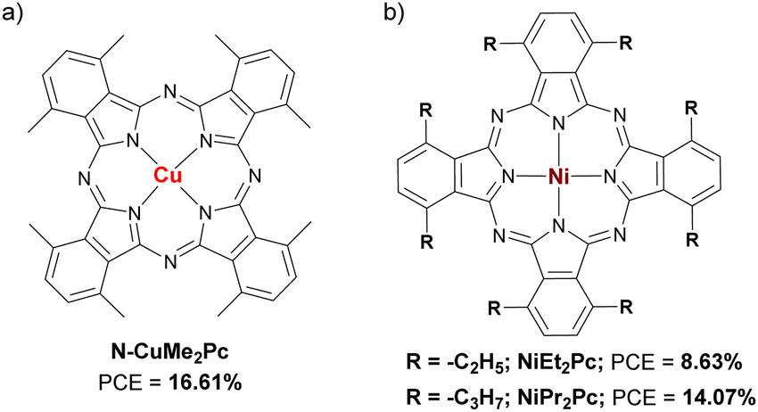
Prof. Xu's group published a study in which the HTL was constituted by N-CuMe2Pc/P3HT nanocomposites (Fig. 5a and Table 1). The properties of the pristine P3HT layer were compared to those containing N-CuMe2Pc, finding that the latter had better qualities and reduced trap densities. With a PCE = 16.61% as the best efficiency, it was the N-CuMe2Pc/P3HT 1:1 ratio that led to the best performance. Regarding long-term stability, the devices with the N-CuMe2Pc/P3HT 1:1 HTL retained 90% of their initial PCE after 800 h of storage with a relative humidity of 75%.35 In 2021, Qi et al. published a study comparing two α-octaalkyl-NiPcs as dopant-free HTMs in planar PSCs, namely NiEt2Pc and NiPr2Pc (Fig. 5b and Table 1). The objective of this study was to determine the influence of the length of the α-side chains on the optoelectronic and photovoltaic properties of these derivatives. The hole mobility of NiPr2Pc was higher than that of NiEt2Pc by more than an order of magnitude (3.64 × 10⁻⁴vs. 1.33 × 10⁻⁵ cm2 V−1 s−1). In addition, it was determined that the LUMO of NiPr2Pc (−3.43 eV) was more favorable to avoid charge carrier recombination in the perovskite/HTL interface than that of NiEt2Pc (−3.61 eV). Thus, NiPr2Pc-based devices presented better performance than those based on its counterpart NiEt2Pc (14.07% and 8.63%, respectively). In this work, the long-term stability of the devices that incorporated these HTMs was not studied.36
 |
| | Fig. 5 Chemical structures of (a) N-CuMe2Pc, and (b) NiEt2Pc and NiPr2Pc applied as HTM in n–i–p PSCs. | |
 |
| | Fig. 6 Chemical structures of ZnPc-dimers: (a) ZnPc-p-ZnPc, ZnPc-th-ZnPc, ZnPc-DPP-ZnPc, and (b) ZnPc-t-DPP-t-ZnPc, ZnPc-t-t-ZnPc and ZnPc-t-Spiro-t-ZnPc, applied as HTM in n–i–p PSCs. | |
2.1.3. Amino-substituted Pcs.
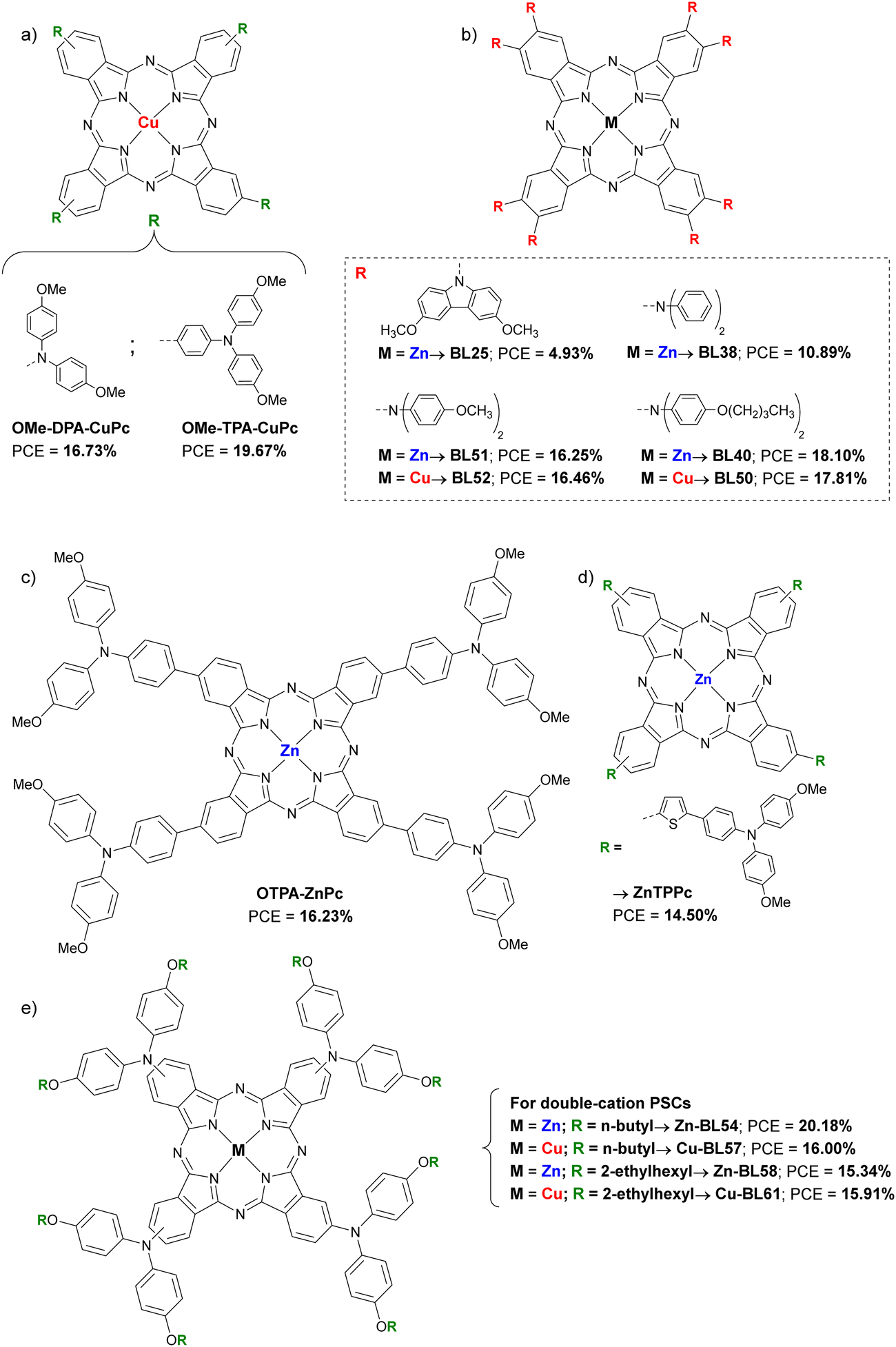
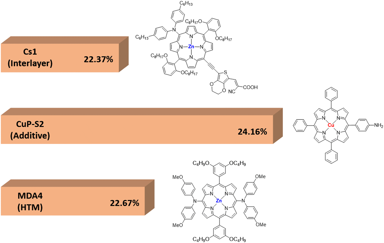
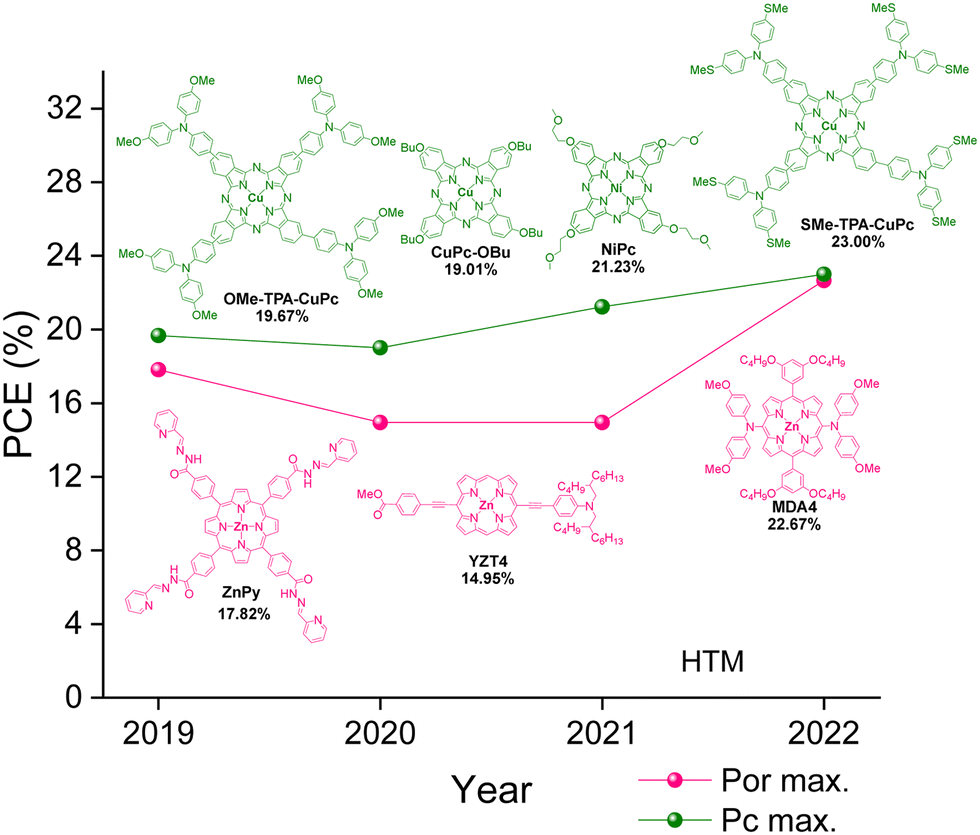
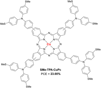
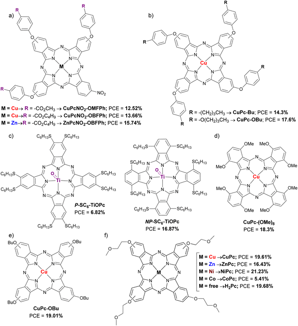
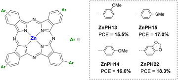
Included here are Pc with alkyl or aryl amines as substituents. Feng et al., published a work in 2019 in which two CuPc (OMe-DPA-CuPc and OMe-TPA-CuPc; Fig. 7a and Table 2) were designed and synthesized guided by computational modeling, and were applied as dopant-free HTMs in planar triple-cation perovskite devices. OMe-TPA-CuPc exhibited the best PSC performance, with the record so far for dopant-free HTMs in PSCs of 19.67% efficiency. Besides, stability tests without encapsulation with a relative humidity of 75%, exposed to room light and at room temperature for more than 960 h showed that these derivatives provide greater long-term stability to PSCs than doped spiro-OMeTAD.44 Cho et al. presented that same year a study in which they synthetized six symmetric diarylamino octasubstituted Pcs, two CuPcs (BL52, BL50) and four ZnPcs (BL25, BL38, BL51 and BL40) as doped HTMs in planar triple-cation PSCs (Fig. 7b and Table 2). Those Pcs with bis(4-butoxyphenyl)amino substituents gave rise to the best performances, with a PCE of 17.81% for the CuPc BL50 and a 18.10% in the case of the ZnPc BL40. In addition, it is observed that the efficiency is greater the shallower the HOMO level is. On this occasion, the ZnPc has shown better performance than that of CuPc, with a maximum PCE 1.6% higher.45 Another example of aminoPc is the one presented in the work of Cui et al., in which the Pc named OTPA-ZnPc (Fig. 7c and Table 2) is compared as dopant-free HTM in mesoporous PSCs with doped spiro-OMeTAD. Although the reference HTM was better than OTPA-ZnPc in terms of initial performance (18.23% vs. 16.23%), the stability test which consisted in storage for 720 h in ambient air, showed that this material was superior to doped spiro-OMeTAD.46 In 2020, in a work by Huang et al.ZnTTPc was presented as dopant-free HTM on 3D devices (Fig. 7d and Table 2). This poorly symmetric Pc had four (((4-methoxyphenyl)amino)phenyl)thiophen-2-yl pendant groups, which provide a hydrophobicity superior to that of spiro-OMeTAD, which was revealed with the contact angle of a water droplet, being that of ZnTTPc 98° and that of spiro-OMeTAD 76°. ZnTTPc-based devices were superior in initial performance to those based on pristine spiro-OMeTAD (14.50% vs. 5.14%, respectively), although the doped spiro-OMeTAD was superior (PCE = 18.47%). As expected, ZnTTPc outperformed the reference material in long-term stability after more than 3000 h of aging, retaining 88% of initial PCE.47 In 2022, Klipfel et al published a study in which four diarylamine-Pcs incorporating either Zn(II) (Zn-BL54 and Zn-BL58; Fig. 7e and Table 2) or Cu(II) (Cu-BL57 and Cu-BL61; Fig. 7e and Table 2) with n-butoxy (Zn-BL54 and Cu-BL57) or 2-ethylhexyloxy (Zn-BL58 and Cu-BL61) side chains were used as doped HTMs in 3D and planar n–i–p PSCs. The devices studied contained triple cation or double cation perovskite active layer. The authors found that the performance of the devices depended not only on the central metal, but also on the alkoxy chains that are attached to diarylamine groups. The best results in terms of PCE were obtained using Zn-BL54 as HTM in both types of PSCs (20.00% for triple cation and 20.18% for double cation). Despite being the least hydrophobic material, Zn-BL54 provided the best stability in 3D triple cation devices after 1000 h under constant illumination. In the case of the double cation planar PSCs, the best stability was achieved with Cu-BL61, which is also the most hydrophobic material under study. The authors highlight that the alkoxy side chains influenced the molecular packing in the solid state of the HTMs, in a way that determined their ability to conduct charges and in the interaction with the perovskite layer.48 In a recently published study, the application of a methylthiotriphenylamine-substituted CuPc (SMe-TPA-CuPc; Fig. 8 and Table 2) as dopant-free HTM in planar PSCs was reported. When SMe-TPA-CuPc was applied on the perovskite layer, it gave rise to PSCs with a maximum efficiency of 20.75%, and after a thermal annealing treatment (85 °C for 22 hours in Ar atmosphere), the PCE improved to 21.51%. The authors attributed this improvement to the fact that Pc penetrates the perovskite layer due to the heat treatment, thus passivating defects not only on the surface but also in the grain boundaries. Analogous PSC devices were studied but adding the additive QAPyBF4 in the perovskite layer, which further improved the PCE up to 23.00%, which is the current record for PSC devices with Pcs as HTM. Furthermore, the long-term stability of these last (encapsulated) devices was higher than when the HTM was spiro-OMeTAD or PTAA, retaining 96% of the initial PCE after more than 3600 h at 85 °C in the dark.49
 |
| | Fig. 7 Chemical structures of amino-substituted Pcs applied as HTM in n–i–p PSCs. | |
Table 2 Hole mobilities and HOMO levels of different amino-substituted Pcs used as HTMs in n–i–p PSCs, along with perovskite composition, device configuration and performances under reverse scan of the best devices
| HTMa |
μ
h (cm2 V−1 s−1) |
HOMO (eV) |
Perovskiteb |
Dopant |
Architecture |
Thickness (nm) |
−Jsc (mA cm−2) |
V
oc (V) |
FF (%) |
PCE (%) |
Ref. |
|
The names of the HTMs are the same as in the original publications.
MA is methylammonium ([CH3NH3]+), FA is formamidinium ([CN2H5]+).
c is compact layer and m means mesoporous layer.
For hole-only diode FTO/PEDOT:PSS/PVK/HTL/Au. — = not provided.
|
| OMe-DPA-CuPc |
1.55 × 10⁻³ |
−5.04 |
Cs0.05(MA0.13FA0.87)0.95Pb(I0.87Br0.13)3 |
No |
FTO/SnO2/Perovs./Pc/Au |
60 |
22.44 |
1.054 |
70.74 |
16.73 |
44
|
| OMe-TPA-CuPc |
6.39 × 10⁻³ |
−5.13 |
Cs0.05(MA0.13FA0.87)0.95Pb(I0.87Br0.13)3 |
No |
FTO/SnO2/Perovs./Pc/Au |
60 |
23.41 |
1.096 |
76.67 |
19.67 |
44
|
| BL25 |
— |
−5.23 |
Cs0.1FA0.74MA0.13PbI2.48Br0.39 |
Li-TFSI/tBP/FK209 |
FTO/TiO2/Perovs./CuPc/Au |
200 |
20.07 |
0.69 |
35.7 |
4.93 |
45
|
| BL38 |
— |
−5.05 |
Cs0.1FA0.74MA0.13PbI2.48Br0.39 |
Li-TFSI/tBP/FK209 |
FTO/TiO2/Perovs./CuPc/Au |
200 |
21.46 |
0.89 |
56.8 |
10.89 |
45
|
| BL40 |
— |
−4.90 |
Cs0.1FA0.74MA0.13PbI2.48Br0.39 |
Li-TFSI/tBP/FK209 |
FTO/TiO2/Perovs./CuPc/Au |
200 |
22.92 |
1.07 |
73.5 |
18.10 |
45
|
| BL50 |
— |
−5.09 |
Cs0.1FA0.74MA0.13PbI2.48Br0.39 |
Li-TFSI/tBP/FK209 |
FTO/TiO2/Perovs./Pc/Au |
200 |
22.52 |
1.06 |
74.2 |
17.81 |
45
|
| BL51 |
— |
−4.92 |
Cs0.1FA0.74MA0.13PbI2.48Br0.39 |
Li-TFSI/tBP/FK209 |
FTO/TiO2/Perovs./CuPc/Au |
200 |
22.58 |
1.04 |
69.4 |
16.25 |
45
|
| BL52 |
— |
−5.10 |
Cs0.1FA0.74MA0.13PbI2.48Br0.39 |
Li-TFSI/tBP/FK209 |
FTO/TiO2/Perovs./Pc/Au |
200 |
22.54 |
1.04 |
70.3 |
16.46 |
45
|
| OTPA-ZnPc |
1.08 × 10⁻⁵ |
−5.58 |
(FAPbI3)0.85(MAPbBr3)0.15 |
No |
FTO/c-TiO2/m-TiO2/Perovs./Pc/Auc |
60 |
22.36 |
1.02 |
71.43 |
16.23 |
46
|
| ZnTTPc |
4.1 × 10⁻⁵ |
−5.15 |
— |
No |
FTO/c-TiO2/m-TiO2/Perovs./Pc/Auc |
60 |
21.00 |
0.9943 |
69.42 |
14.50 |
47
|
| Zn-BL54 |
— |
−4.49 |
FAMAPb(IBr) |
Li-TFSI/tBP/FK209 |
FTO/c-TiO2/m-TiO2/SnO2/PCBM/Perovs./HTM/Au |
170 |
23.87 |
1.07 |
79.00 |
20.18 |
48
|
| Cu-BL57 |
— |
−4.65 |
FAMAPb(IBr) |
Li-TFSI/tBP/FK209 |
FTO/c-TiO2/m-TiO2/SnO2/PCBM/Perovs./HTM/Au |
170 |
23.00 |
0.94 |
74.00 |
16.00 |
48
|
| Zn-BL58 |
— |
−4.74 |
FAMAPb(IBr) |
Li-TFSI/tBP/FK209 |
FTO/c-TiO2/m-TiO2/SnO2/PCBM/Perovs./HTM/Au |
170 |
22.12 |
0.95 |
73.00 |
15.34 |
48
|
| Cu-BL61 |
— |
−4.41 |
FAMAPb(IBr) |
Li-TFSI/tBP/FK209 |
FTO/c-TiO2/m-TiO2/SnO2/PCBM/Perovs./HTM/Au |
170 |
22.57 |
0.94 |
75.00 |
15.91 |
48
|
| SMe-TPS-CuPc |
7.04 × 10⁻⁴d |
−5.49 |
Cs0.05(MA0.13FA0.87)0.95Pb(I0.87Br0.13)3/QAPyBF4 |
No |
FTO/SnO2/Perovs./Pc/Au |
50 |
24.10 |
1.132 |
84.31 |
23.00 |
49
|
 |
| | Fig. 8 Chemical structure of amino-substituted SMe-TPA-CuPc applied as HTM in n–i–p PSCs. | |
2.1.4. Alkoxy/phenoxy-substituted Pcs.
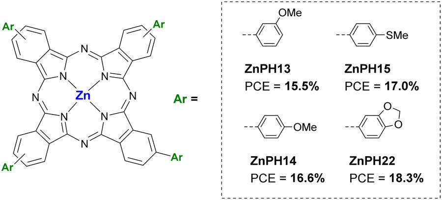
This group includes those Pcs substituted in the α and/or β positions with alkoxy, phenoxy, alkylthio and arylthio substituents. In the work of Guo et al. (2019) three asymmetric Pc A3B with three phenoxyl groups (A) and one nitro group (B) in their peripheral positions were studied as dopant-free HTMs in planar PSCs. In this case, two CuPc (CuPcNO2-OMFPh and CuPcNO2-OBFPh) were compared with a ZnPc (ZnPcNO2-OBFPh) (Fig. 9a and Table 3). The three Pcs showed good thermal stabilities and appropriate energy levels but was ZnPcNO2-OBFPh the one that had the highest hole mobility (11.4 × 10⁻⁵ cm2 V−1 s−1), leading to the best performance (PCE = 15.74%). Additionally, the latter provided better stability than that of the other two Pcs and Spiro-OMeTAD, under continuous light irradiation at 60 °C and MPPT in ambient air without encapsulation after 500 h.50 Jiang et al. presented the same year two CuPcs as dopant-free HTMs for 3D PSCs, CuPc-Bu and CuPc-OBu (Fig. 9b and Table 3). The small difference in molecular structure, by replacing butyl groups by butoxy groups, led to a better morphology of the HTL with the consequent higher hole mobility in the case of CuPc-OBu (4.30 × 10⁻⁴ cm2 V−1 s−1) than CuPc-Bu (1.23 × 10⁻⁴ cm2 V−1 s−1), and better PSC performance, with a PCE of 17.6% for CuPc-OBuvs. 14.3% for CuPc-Bu. Stability studies showed that CuPc-OBu provides greater stability than doped spiro-OMeTAD after 120 h in ambient conditions with a RH of 85%.51 The application as dopant-free HTM of two titanyl Pc (P-SC6-TiOPc and NP-SC6-TiOPc; Fig. 9c and Table 3). in planar PSCs was studied by Hu et al. in 2019. The difference between these two Pcs is that they are octasubstituted with n-hexylthio groups at the α (P-SC6-TiOPc) or β positions (NP-SC6-TiOPc). The authors determined through experimental and theoretical studies that substituents in β-positions leaded to weaker π–π interactions than if they were in the α-position due to less spatial hindrance and larger rotation angles of the β-substituted Pcs. Thus, that resulted in lower crystallinity and low-quality film formation with poor coverage, leading to lower hole mobility, high recombination rates at the interfaces and the fast degradation of the underlying perovskite layer in the PSC devices. In this way, PSCs containing NP-SC6-TiOPc had better performances (PCE = 16.87%) than those with P-SC6-TiOPc (PCE = 6.82%). NP-SC6-TiOPc also showed better long-term stability than its counterpart and doped spiro-OMeTAD at 25 °C under the relative humidity of 75%.52 Ding et al. published that year an article in which they compared a octa-methoxy-CuPc (CuPc-(OMe)8; Fig. 9d and Table 3) as dopant-free HTM in planar PSCs to doped spiro-OMeTAD. This α-substituted Pc was slightly inferior to its counterpart in terms of performance (PCE = 18.3% vs. 18.7%), but the CuPc-(OMe)8-based devices had a higher stability after 30 days stored without encapsulation (RH 40–50%), maintaining 90% of their initial efficiency, which was attributed to the absence of dopants and a greater hydrophobic nature of Pc, which was demonstrated with the contact angle of a water droplet.53 In triple cation lead-based 3D PSCs, Li et al. studied a Pc named CuPc-OBu as dopant-free HTM also in 2020 (Fig. 9e and Table 3). In this study, this CuPc-OBu was processed in solution with tBP, after which the latter was removed by thermal annealing, then considering it virtually dopant-free HTM. Compared with doped spiro-OMeTAD, CuPc-OBu-based devices were efficient enough (PCE= 19.01% vs. 19.96% for spiro-OMeTAD-based devices) and more stable than the spiro-OMeTAD-based devices when subjected to 85 °C with 45% RH for 1000 h. Besides, in Sn-based 3D PSCs, and comparing it this time with the polymer PTAA, CuPc-OBu-based devices were more efficient and more stable than its polymeric counterpart.54 In a work published by Yu et al. in 2021, a really interesting comparison can be found between Pcs with different central metals but with the same peripheral methoxyethoxy substituents (CoPc, NiPc, CuPc, ZnPc and H2Pc; Fig. 9f and Table 3). All these materials were applied as dopant-free HTMs on 3D PSCs. The HOMO levels of these Pcs were similar, between −5.22 eV and −5.25 eV, except in the case of CoPc, which was −4.97 eV. The Pc with the highest hole mobility was NiPc (1.1 ± 0.2 × 10⁻⁴ cm2 V−1 s−1), whilist CoPc had the lowest (8.8 ± 0.3 × 10⁻⁶ cm2 V−1 s−1), all the others were of the order of 10−5 cm2 V−1 s−1. After optimizing the thickness of the HTMs (30 nm), NiPc revealed an impressive PCE of 21.23% (certified 21.03%), in contrast to the maximum PCE of 5.41% that was obtained with CoPc-based devices. CuPc, ZnPc and H2Pc-based devices performed PCEs of 19.61%, 16.43% and 19.68%, respectively. Only the stability provided by NiPc compared to control devices with spiro-OMeTAD was studied. The unsurprising result was that the NiPc-containing devices were more stable both in air at room temperature with a humidity of 65%, at 85 °C in N2 atmosphere (thermal stability test) and at AM 1.5G illumination in N2 atmosphere (photo-stability test). NiPc-based devices retained 90% of their initial PCE after 1000 h, while spiro-OMeTAD devices lost 90% of their initial efficiency after 700 h in thermal a photo-stability tests.55 Chen et al. applied four ZnPcs as dopant-free HTMs in 3D PSCs, in 2021 as well. These are tetra-β-substituted-Pcs that are mixtures of regioisomers, with 3-methoxyl (ZnPH13), 4-methylthio (ZnPH15), 4-methoxyl (ZnPH14) and benzo[d][1,3]dioxole (ZnPH22) groups (Fig. 10 and Table 3). ZnPH22 is the derivative with the shallowest LUMO (−3.38 eV) and the highest hole mobility (2.8 × 10⁻⁴ cm2 V−1 s−1), which, together with its better morphology in a thin layer, resulted in the best performance of 18.3% PCE. In the stability studies, the four ZnPc were compared to doped spiro-OMeTAD as reference. While after 480 h of aging at 25–30 °C at 35–40% RH, ZnPH13, ZnPH14, ZnPH15 and ZnPH22 based devices retained 85%, 87%, 88% and 90% of the initial PCE, respectively, spiro-OMeTAD-based device lost more than 80% of the initial PCE. Furthermore, a ZnPH22-based device was also tested at 85 °C for 25 minutes, demonstrating better stability than that of control device.56
 |
| | Fig. 9 Chemical structures of alkoxy/phenoxy-substituted Pcs applied as HTM in n–i–p PSCs. | |
Table 3 Hole mobilities and HOMO levels of different alkoxy/phenoxy-substituted Pcs used as HTMs in n–i–p PSCs, along with perovskite composition, device configuration and performances under reverse scan of the best devices
| HTMa |
μ
h (cm2 V−1 s−1) |
HOMO (eV) |
Perovskiteb |
Dopant |
Architecture |
Thickness |
−Jsc (mA cm−2) |
V
oc (V) |
FF (%) |
PCE (%) |
Ref. |
|
The names of the HTMs are the same as in the original publications.
MA is methylammonium ([CH3NH3]+), FA is formamidinium ([CN2H5]+).
c is compact layer and m means mesoporous layer. — = not provided.
|
| CuPcNO2-OMFPh |
5.02 × 10⁻⁵ |
−4.98 |
(FAI)0.85(PbI2)0.85(MABr)0.15(PbBr2)0.15 |
No |
FTO/c-TiO2/m-TiO2/Perovs./Pc/Auc |
— |
20.01 |
1.02 |
60.0 |
12.52 |
50
|
| CuPcNO2-OBFPh |
8.21 × 10⁻⁵ |
−4.96 |
(FAI)0.85(PbI2)0.85(MABr)0.15(PbBr2)0.15 |
No |
FTO/c-TiO2/m-TiO2/Perovs./Pc/Auc |
— |
20.62 |
1.04 |
64.0 |
13.66 |
50
|
| ZnPcNO2-OBFPh |
11.4 × 10⁻⁵ |
−4.95 |
(FAI)0.85(PbI2)0.85(MABr)0.15(PbBr2)0.15 |
No |
FTO/c-TiO2/m-TiO2/Perovs./Pc/Auc |
40 nm |
21.00 |
1.10 |
68.00 |
15.74 |
50
|
| CuPc-Bu |
1.23 × 10⁻⁴ |
−5.12 |
(FAPbI3)0.85(MAPbBr3)0.15 |
No |
FTO/c-TiO2/m-TiO2/Perovs./Pc/Auc |
40 nm |
21.0 |
1.03 |
66.0 |
14.3 |
51
|
| CuPc-OBue |
4.30 × 10⁻⁴ |
−5.11 |
(FAPbI3)0.85(MAPbBr3)0.15 |
No |
FTO/c-TiO2/m-TiO2/Perovs./Pc/Auc |
40 nm |
22.8 |
1.06 |
73.0 |
17.6 |
51
|
|
P-SC6-TiOPc |
1.16 × 10⁻⁵ |
−5.32 |
Cs0.05(MA0.13FA0.87)0.95Pb(I0.87Br0.13)3 |
No |
FTO/SnO2/Perovs./Pc/Au |
60 nm |
19.92 |
0.95 |
36.04 |
6.82 |
52
|
|
NP-SC6-TiOPc |
1.17 × 10⁻⁴ |
−5.07 |
Cs0.05(MA0.13FA0.87)0.95Pb(I0.87Br0.13)3 |
No |
FTO/SnO2/Perovs./Pc/Au |
60 nm |
22.31 |
1.06 |
71.34 |
16.87 |
52
|
| CuPc-(OMe)8 |
1.10 × 10⁻³ |
−5.18 |
(FAPbI3)0.85(MAPbBr3)0.15 |
No |
FTO/SnO2/Perovs./Pc/Au |
100 nm |
22.1 |
1.05 |
79.0 |
18.3 |
53
|
| CuPc-OBue |
3.6 × 10⁻⁵ |
−4.7 |
Cs0.05(MA0.17FA0.83)0.95Pb(I0.83Br0.17)3 |
No |
FTO/c-TiO2/m-TiO2/Perovs./Pc/Auc |
30 nm |
23.11 |
1.07 |
77.12 |
19.01 |
54
|
| CuPc |
7.3 ± 0.2 × 10⁻⁵ |
−5.22 |
Cs0.05(FA0.83MA0.17)0.95Pb(I0.83Br0.17)3 |
No |
FTO/SnO2/m-TiO2/Perovs./Pc/Auc |
30 nm |
23.96 |
1.10 |
74.05 |
19.61 |
55
|
| ZnPc |
1.5 ± 0.4 × 10⁻⁵ |
−5.25 |
Cs0.05(FA0.83MA0.17)0.95Pb(I0.83Br0.17)3 |
No |
FTO/SnO2/m-TiO2/Perovs./Pc/Auc |
30 nm |
22.91 |
1.06 |
67.70 |
16.43 |
55
|
| NiPc |
1.1 ± 0.2 × 10⁻⁴ |
−5.23 |
Cs0.05(FA0.83MA0.17)0.95Pb(I0.83Br0.17)3 |
No |
FTO/SnO2/m-TiO2/Perovs./Pc/Auc |
30 nm |
23.92 |
1.13 |
78.66 |
21.23 |
55
|
| CoPc |
8.8 ± 0.3 × 10⁻⁶ |
−4.97 |
Cs0.05(FA0.83MA0.17)0.95Pb(I0.83Br0.17)3 |
No |
FTO/SnO2/m-TiO2/Perovs./Pc/Auc |
30 nm |
11.03 |
0.96 |
51.28 |
5.41 |
55
|
| H2Pc |
6.1 ± 0.3 × 10⁻⁵ |
−5.24 |
Cs0.05(FA0.83MA0.17)0.95Pb(I0.83Br0.17)3 |
No |
FTO/SnO2/m-TiO2/Perovs./Pc/Auc |
30 nm |
23.85 |
1.11 |
74.36 |
19.68 |
55
|
| ZnPH13 |
8.9 × 10⁻⁵ |
−5.23 |
(FAPbI3)0.85(MAPbBr3)0.15 |
No |
FTO/c-TiO2/m-TiO2/Perovs./Pc/Auc |
— |
20.0 |
1.03 |
75.0 |
15.5 |
56
|
| ZnPH14 |
1.4 × 10⁻⁴ |
−5.18 |
(FAPbI3)0.85(MAPbBr3)0.15 |
No |
FTO/c-TiO2/m-TiO2/Perovs./Pc/Auc |
— |
21.0 |
1.05 |
76.0 |
16.6 |
56
|
| ZnPH15 |
1.7 × 10⁻⁴ |
−5.16 |
(FAPbI3)0.85(MAPbBr3)0.15 |
No |
FTO/c-TiO2/m-TiO2/Perovs./Pc/Auc |
— |
21.6 |
1.05 |
75.0 |
17.0 |
56
|
| ZnPH22 |
2.8 × 10⁻⁴ |
−5.13 |
(FAPbI3)0.85(MAPbBr3)0.15 |
No |
FTO/c-TiO2/m-TiO2/Perovs./Pc/Auc |
— |
22.5 |
1.06 |
77.0 |
18.3 |
56
|
 |
| | Fig. 10 Chemical structures of phenoxy substituted ZnPcs applied as HTM in n–i–p PSCs. | |
2.2. Phthalocyanines as HTM in p–i–n PSCs
The most relevant examples of PCs applied as HTM in inverted devices (p–i–n) are exposed in this section. In the first place, the works that involved non-substituted Pcs as HTM will be exposed and then those that involved substituted Pcs.
2.2.1. Non-substituted Pcs.
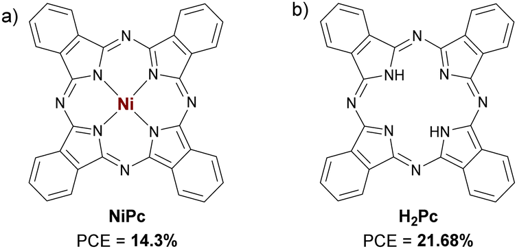
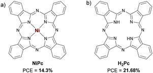
Some of the non-substituted Pcs that are going to be exposed here have already been mentioned in Section 2.1.1. Haider et al. applied in 2019 the non-substituted NiPc (Fig. 11a and Table 4) and CuPc (Fig. 4a and Table 4) as HTMs in planar devices to study which one is the most suitable HTM. NiPc was the HTM that provided the highest efficiency (PCE = 14.3%) and showed a lower hysteresis behavior, while CuPc resulted in a PCE of 14.1%. For the stability tests, NiPc was compared to PEDOT:PSS as HTM, the former being superior to the latter under the conditions tested.57 In 2020, Tavakoli et al. made planar PSCs by using an all-vacuum processing technique with CuPc (Fig. 4a; named e-CuPC) as HTM. When they compared the performance of these devices with those of solution processed-CuPc-HTM PSCs (Fig. 4a; named s-CuPC), a superior efficiency was found in the case of all-vacuum processed PSCs, that is, 20.3% PCE for e-CuPCversus 16.8% PCE for s-CuPC. Additionally, flexible PSCs were fabricated on a polyethylene terephthalate (PET) substrate, with a PCE of 18.51%. The devices based on e-CuPC showed a higher stability than those based on s-CuPC.58 In 2021, Seto published an article comparing CuPc (Fig. 4a and Table 4) with PEDOT:PSS as dopant-free HTMs in planar devices. As usual, CuPc outperformed its polymeric counterpart both in terms of efficiency and stability, reaching a PCE of 16.13% under reverse scan and retaining the initial PCE after 30 days of aging in air.59 Recently, in 2022, Zhao et al. mixed the metal-free H2Pc (Fig. 11b and Table 4) with NiOx to form the HTL in p–i–n PSCs. The conductivity of NiOx increased over 300% when mixed with H2Pc (2 mg mL−1), which caused an improvement in PCE from 19.74% to 21.68%, and an enhanced stability, retaining over 95% of the initial PCE after 85 °C aging for 800 h.60
 |
| | Fig. 11 Chemical structures of (a) NiPc and (b) H2Pc applied as HTMs in p–i–n PSCs. | |
Table 4 Hole mobilities and HOMO levels of different Pcs used as HTMs in p–i–n PSCs, along with perovskite composition, device configuration and performances under reverse scan of the best devices
| HTMa |
μ
h (cm2 V−1 s−1) |
HOMO (eV) |
Perovskiteb |
Dopant |
Architecturec |
Thickness |
−Jsc (mA cm−2) |
V
oc (V) |
FF (%) |
PCE (%) |
Ref. |
|
The names of the HTMs are the same as in the original publications.
MA is methylammonium ([CH3NH3]+), FA is formamidinium ([CN2H5]+).
The device type in planar unless otherwise stated.
Performance under forward scan.
The provided value is the conductivity of Pc-NiOx layer, in S cm−1.
It is the thickness of the Pc-NiOx layer.
Measured under forward scan. — = not provided.
|
| NiPc |
— |
−5.0 |
FA0.78MA0.21Pb(I0.78Br0.21)3 |
No |
ITO/Pc/Perovs./PC61BM/BCP/Ag |
30 nm |
19.45 |
1.0e |
73.6e |
14.3e |
57
|
| CuPc |
— |
— |
FA0.78MA0.21Pb(I0.78Br0.21)3 |
No |
ITO/Pc/Perovs./PC61BM/BCP/Ag |
30 nm |
18.94 |
0.99e |
75.1e |
14.1e |
57
|
| e-CuPC |
— |
−5.2 |
MAPbI3 |
No |
ITO/Pc/Perovs./C60/BCP/Ag |
7 nm |
23.34d |
1.108d |
78.5d |
20.3 |
58
|
|
|
|
|
MAPbI3 |
|
PET/ITO/Pc/Perovs./C60/BCP/Agd |
|
22.65d |
1.10d |
75.0d |
18.68 |
58
|
| s-CuPC |
— |
−5.15 |
MAPbI3 |
Li-TFSI/tBP |
ITO/Pc/Perovs./C60/BCP/Ag |
20 nm |
21.41 |
1.09 |
72.0 |
16.8 |
58
|
| CuPc |
— |
−5.2 |
MAPbI3 |
No |
TCO/Pc/Perovs./C60/BCP/Ag |
5 nm |
22.4 |
0.985 |
73.1 |
16.13 |
59
|
| H2Pc + NiOx |
4.6 × 10⁻⁴ |
−5.28 |
(FAPbI3)0.97(MAPbBr3)0.03 |
No |
ITO/HTL/Perovs./PCBM/C60/TPBi/Cu |
100 nmf |
25.63g |
1.11g |
75.94g |
21.68g |
60
|
| TT1 |
— |
−5.4 |
MAPbI3 |
No |
ITO/Pc/Perovs./C60/Ag |
— |
18.85g |
1.05g |
69.3g |
14.85g |
61
|
| TS-CuPc/Spiro-OMeTAD |
— |
−5.35 |
CsPbI2Br |
No |
ITO/HTL/Perovs./Nano-Eu2O3/Bphen/PC61BM/Ag |
40 ± 5 nm |
15.53 |
1.185 |
80.7 |
14.85 |
63
|
| TS-CuPc |
— |
— |
MAPbI3 |
PEDOT:PSS |
ITO/HTL/Perovs./PC61BM/BCP/Ag |
9–11 nm |
19.861 |
0.950 |
77.64 |
14.65 |
64
|
| TS-NiPc |
— |
— |
MAPbI3 |
PEDOT:PSS |
ITO/HTL/Perovs./PC61BM/BCP/Ag |
9–11 nm |
18.562 |
0.920 |
74.35 |
12.70 |
64
|
2.2.2. Substituted Pcs.
Aktas et al. presented the asymmetric Pc TT1 (Fig. 12a and Table 4) as a unit capable of self-organizing in self-assembled monolayers (SAMs) to form an ultrathin HTL in planar devices. Compared to PEDOT:PSS (PCE = 13.71% in forward scan), TT1 provided a higher performance, with a PCE of 14.85% in forward scan. The author related this result to the HOMO difference between both HTMs. There were no stability studies in this article.61 Dalkılıç et al. published a study in 2020 where they applied two ZnPcs and their two copper analogs tetra and octa-substituted with (2,4-dichlorophenyl)thio substituents as dopant-free HTMs in planar devices to compare how the different peripheral substitution affects the optoelectronic properties of these materials and, therefore, their photovoltaic performance. They concluded that tetra-substituted Pcs provided better performances than octa-substituted ones, although any of them was better than PEDOT:PSS-based control devices. Regarding the central metal, CuPcs were better than ZnPcs in this case. In this work, the stability of the devices was not investigated either.62 Han et al., in 2021, applied a doble HTL in planar PSCs This doble HTL was made up of undoped spiro-OMeTAD and CuPc 3,4′,4′′,4′′′-tetrasulfonated acid tetrasodium salt (TS-CuPc; Fig. 12c and Table 4). With a PCE of 14.85%, devices with this double HTL were superior in terms of efficiency and stability than pristine spiro-OMeTAD (11.53% PCE), pristine TS-CuPc (14.45% PCE), NiOx (13.88%), and PEDOT:PSS (3.56% PCE) and their combinations counterparts. Those devices with double HTL showed greater stability than those with only spiro-OMeTAD-based HTL in both the thermal test (85 °C in N2 for 450 h) and the humidity test (25 °C at 60–70% RH for 1200 h).63 This same year another article was also published in which TS-CuPc (Fig. 12c and Table 4) doped with PEDOT:PSS was applied, comparing it with TS-NiPc (Fig. 12d and Table 4) also doped with the same polymer. The performance and stability of the devices with both types of doped TS-MPcs were compared to pristine PEDOT:PSS. Thus, the best performances were achieved by adding 10% PEDOT:PSS to the Pc solutions. Doped TS-CuPc was the best HTM, with a PCE of 14.65%, while PCEs of 12.70% and 11.02% with TS-NiPc and PEDOT:PSS were respectively obtained. Self-stability was tested storing the unencapsulated devices in ambient air for 336 h. Unlike TS-CuPc and TS-NiPc, which retained about 70% of the initial PCEs, PEDOT:PSS rapidly degraded.64
 |
| | Fig. 12 Chemical structures of (a) TT1, (b) Ts-CuPc/Spiro-OMeTAD, (c) TS-CuPc and (d) TS-NIPc applied as HTMs in p–i–n PSCs. | |
2.3. Phthalocyanines as perovskite additives in PSCs
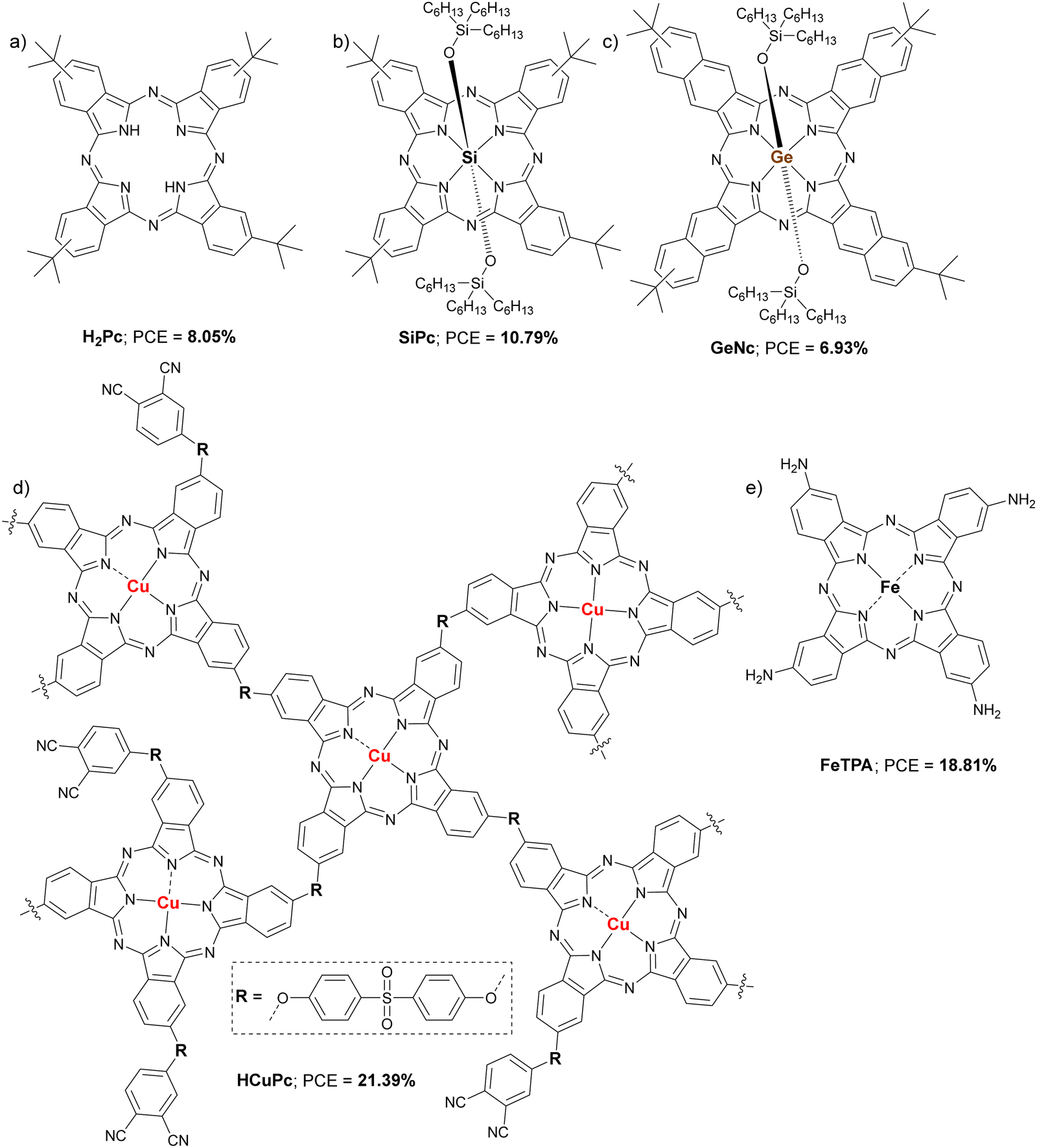
In this section, some articles are going to be reviewed in which the use of Pcs as additives in the active layer of perovskite is described. The first one is from 2019, where Suzuki et al. applied a metal-free Pc (H2Pc; Fig. 13a and Table 5), a silicon Pc (SiPc; Fig. 13b and Table 5) and a germanium naphthalocyanine (GeNc; Fig. 13c and Table 5) perovskite additives in n–i–p 3D devices (Fig. 13 and Table 5). Among the three compounds tested, SiPc gave rise to the best results in terms of device performance (PCE = 10.79%). This result was attributed to an improvement in crystal growth, which led to suppression of defects and pinholes.65 In the following work, from 2021, the addition of small amounts of CuPc in the ultrathin active layer MAPbI3 in n–i–p planar devices was described. The authors study both the concentration of CuPc (% weight) and the thickness of the perovskite layer, being their objective to determine if adding CuPc in the active layer can retain the performance of standard devices in devices with ultrathin active layers. They found that adding 15% CuPc in an active layer of about 150 nm, 82% of PCE of a standard device (around 450 nm perovskite thickness) was retained (12.7% PCE vs. 15.4% PCE).66 The third work was recently published by Li et al., in which they present a Pc pentamer (HCuPc; Fig. 13d and Table 5) included as additive in FAPbI3 p–i–n planar devices. When 0.05% by weight of HCuPc was added to the perovskite mixture, the performance of the devices was significantly improved, going from a PCE of 18.73% without HCuPc to 21.39% with HCuPc, which was a record for p–i–n devices based on FAPbI3 processed under ambient conditions with RH of 85%. Devices containing the additive HCuPc were more stable than without it under illumination (1 sun in N2, 600 h), heating (N2 atmosphere at 80 °C, 450h), and electric field conditions (in air, 30–40% RH, 100h).67 Recently, a work has been published in which the iron tetraaminophthalocyanine FeTAP (Fig. 13e and Table 5) was used as an additive in the perovskite layer of 3D n–i–p devices. According to this study, the addition of 0.2% wt of FeTAP in the active layer led to a higher quality of the crystals, since they were larger than without the additive. It is also shown that the grain boundaries were filled and that the uncoordinated lead cations were passivated with the Pc molecules. Additionally, a lower hysteresis behavior was observed by using FeTAP. All this led to a maximum PCE of 18.81% for FeTAP additive devices, compared to 16.80% for devices with the pristine active layer. An improved stability was also stablished after 30 days of storage under an inert N2 atmosphere.68
 |
| | Fig. 13 Chemical structures of (a) H2Pc, (b) SiPc, (c) GeNc, (d) oligomer HCuPc and (e) FeTPA used as additives in PSCs and the PCE of the champion devices. | |
Table 5 Parameters of Pcs used in different roles in PSCs, along with perovskite composition, device configuration and performances under reverse scan of the best devices
| Pca |
Role |
μ (cm2 V−1 s−1) |
LUMO (eV) |
HOMO (eV) |
Perovskiteb |
Architecture |
Thickness |
Wt% |
−Jsc (mA cm−2) |
V
oc (V) |
FF (%) |
PCE (%) |
Ref. |
|
The names of the compounds are the same as in the original publications, although the repetitions have been modified.
MA is methylammonium ([CH3NH3]+), FA is formamidinium ([CN2H5]+).
The value of x is not clarified in the original work.
Carbon-based electrode additive.
This HOMO level value corresponds to the mixture of carbon with 1% CuPc.
The perovskite formula is not made clear in the original paper. — = not provided.
|
| H2Pc |
Additive |
— |
|
— |
MAPbI3−xClxc |
FTO/c-TiO2/m-TiO2/Perovs.-Pc/HTL/Au |
— |
0.3 |
14.2 |
0.924 |
61.6 |
8.05 |
65
|
| SiPc |
Additive |
— |
|
— |
MAPbI3−xClx |
FTO/c-TiO2/m-TiO2/Perovs.-Pc/HTL/Au |
— |
0.5 |
20.6 |
0.874 |
59.9 |
10.79 |
65
|
| GeNc |
Additive |
— |
|
— |
MAPbI3−xClx |
FTO/c-TiO2/m-TiO2/Perovs.-Pc/HTL/Au |
— |
0.3 |
14.1 |
0.926 |
53.0 |
6.93 |
65
|
| CuPc |
Additive |
— |
|
−5.25 |
MAPbI3 |
ITO/PEDOT:PSS/Perovs./PC61BM/BCP/Ag |
— |
15 |
17.48 |
0.94 |
77.0 |
12.7 |
66
|
| HCuPc |
Additive |
1.14 × 10⁻⁴ |
|
— |
FAPbI3 |
TO/PTAA/Perovs.-Pc/PMMA/C60/BCP/Cu |
— |
0.05 |
25.57 |
1.032 |
81.05 |
21.39 |
67
|
| FeTAP |
Additive |
— |
|
— |
(FAPbI3)0.95(MAPbBr2)0.05(CsI)f |
FTO/c-TiO2/m-TiO2/Perovs./HTL/MoO3/Ag |
— |
0.2 |
23.76 |
1.11 |
73.26 |
18.81 |
68
|
| Pc |
Passivator |
— |
|
−5.01 |
Cs0.05FA0.81MA0.14PbI2.55Br0.45 |
FTO/TiO2/Perovs./Pc/HTL/Au |
— |
— |
22.3 |
1.16 |
76.2 |
19.8 |
69
|
| SnPc |
Interlayer |
— |
|
−5.24 |
MAPbI3 |
FTO/c-TiO2/m-TiO2/Perovs./Pc/HTL/Au |
— |
— |
23.41 |
1.038 |
68.0 |
16.52 |
70
|
| SiPc-Py-2 |
Interlayer |
3.95 ± 0.5 × 10⁻⁴ |
−3.7 |
−5.3 |
MAPbI3 |
ITO/PTAA/Perovs./Pc/PTCDA/HBL/Cu |
5 nm |
— |
22.70 |
1.10 |
76.5 |
19.2 |
71
|
|
NP-SC6-TiOPc |
Passivator |
— |
|
−5.07 |
MAPbI3 |
FTO/SnO2/Perovs./Pc/HTL/Au |
— |
— |
23.27 |
1.12 |
74.40 |
19.39 |
72
|
|
NP-SC6-ZnPc |
Passivator |
— |
|
−4.98 |
MAPbI3 |
FTO/SnO2/Perovs./Pc/HTL/Au |
— |
— |
23.18 |
1.09 |
71.40 |
18.04 |
72
|
| S2 |
Passivator |
— |
|
−5.49 |
MAPbI3 |
FTO/SnO2/Perovs./Pc/HTL/Au |
— |
— |
22.57 |
1.024 |
71.45 |
16.64 |
73
|
| S3 |
Passivator |
— |
|
−5.53 |
MAPbI3 |
FTO/SnO2/Perovs./Pc/HTL/Au |
— |
— |
22.75 |
1.033 |
76.55 |
18.01 |
73
|
| 8TPAEPC |
Passivator |
3.12 × 10⁻³ |
−3.86 |
−5.45 |
Cs0.05(FA0.83MA0.17)0.95Pb(I0.83Br0.17)3 |
FTO/c-TiO2/m-TiO2/Perovs.-Pc/HTL/Au |
— |
2.5 mg mL−1 |
24.00 |
1.123 |
82.00 |
22.1 |
74
|
| CuPc |
CE-additived |
— |
|
−4.22e |
MAPbI3 |
FTO/c-TiO2/Perovs./Carbon-CuPc |
— |
1.0 |
21.4 |
1.02 |
68.0 |
14.8 |
76
|
2.4. Phthalocyanines as passivating agents and interlayers in PSCs
In this section, the most important works on Pcs applied as passivating agents and interlayers will be presented. In 2019, Zhang et al. dissolved Pc (also named H2Pc in Fig. 13a and Table 5) in anisole to drop it as antisolvent in the perovskite processing in planar n–i–p PSCs. This molecule remained in the superficial layers of the perovskite and the grain boundaries, passivating the defects. In this way, the efficiency improved from a PCE of 18.5% for control devices to 19.8% for devices optimally passivated with Pc. Stability was also improved, retaining more than 90% of the initial PCE after 500 h under continuous illumination in air at 30% RH. All these improvements were ascribed to the decreased perovskite hole trap state density, the increased perovskite hole mobility, improved charge carrier transfer and extraction, and partially sealed channels to impede moisture diffusion because of the Pc passivation.69 This same year, SnPc (Fig. 14a and Table 5) was applied as an interlayer in 3D n–i–p PSCs by Lai et al. This interlayer improved the hole transport and reduced charge recombination, leading to a performance improvement from 13.2% PCE for pristine devices to 16.52% PCE for those with the interlayer. Due to the hydrophobicity of SnPc, the stability was also improved, retaining 84% of the original PCE after 90 days in air at around 30% RH.70 Xie et al. studied the same year a silicon Pc (SiPc-Py-2; Fig. 14b and Table 5) as an interlayer but this time between the perovskite layer and the ETL in fullerene-free p–i–n PSCs. SiPc-Py-2 has two 2-(pyren-1-yl)acetoxy substituents in the axial positions, that is, bonded to the central silicon atom. It was found to passivate the trap states on the surface of perovskite through interactions as a Lewis base. The champion device reached 19.2% PCE and showed greater thermal stability in unencapsulated devices (160 h at 90 °C).71 Later, in 2020, Hu et al. applied NP-SC6-ZnPc and NP-SC6-TiOPc as passivating agents in planar n–i–p PSCs (Fig. 14c and Table 5). These derivatives have eight thioether chains in the α-positions, in fact NP-SC6-TiOPc has already been discussed as HTM in n–i–p PSCs in the alkoxy/phenoxy-substituted-Pcs part.52 The presence of N, O, and S heteroatoms with lone pairs of electrons in the Pc macrocycles makes possible Lewis acid-base interactions with uncoordinated Pb2+ cations, which leads to the passivation of defects, thus improving the morphology of the active layer with the consequent improvement in performance, from 17.67% PCE for devices with pristine perovskite to 19.39% and 18.04% for devices containing perovskite passivated with NP-SC6-TiOPc and NP-SC6-ZnPc, respectively. As expected, those devices with the passivating layer were more stable versus moisture and thermal stress than pristine ones.72 Another relevant example was the application of two non-metalated Pcs (S2 and S3; Fig. 14d and Table 5), which are isomers of each other, as passivating agents. These Pcs have butoxyl substituents in all α-positions and ethynylthiophene in all β-positions, 2-thiophenylethynyle for S2 and 3-thiophenylethynyle for S3. According to the HOMO and LUMO levels provided by the authors (−5.49 eV and −4.13 eV for S2, and −5.53 eV and −4.15 eV for S3), these materials would work better in the ETL part, however they were interposed between the active layer and the HTL (spiro-OMeTAD). Devices with pristine MAPbI3 performed worse than devices passivated with S3, going from a PCE of 16.88% to one of 18.01%. On the contrary, in the case of S2 there was no improvement, with PCE slightly lower than that of the devices without passivation (16.64%). S3 provided better stability than S2 and the pristine perovskite.73 Finally, the addition of the CuPc 8TPAEPC (Fig. 14e and Table 1) dissolved in the antisolvent (chlorobenzene) on the perovskite layer gave rise to the improvement of the PCE from 20% to 22.10%, which was attributed not only to the extension of the NIR photoresponse from 760 to 850 nm, but also to defect suppression due to a better crystallization of the active layer as well as a reduction of the trap-state density through the interaction with the I− anions. Devices containing 8TPAEPC retained 80% of the initial PCE after 500h at 70–80% RH, whilst pristine PSC dropped 50% of the initial PCE. 8TPAEPC was also applied as dopant-free HTM yielding 20.42% PCE and showing that also provides good moisture stability.74
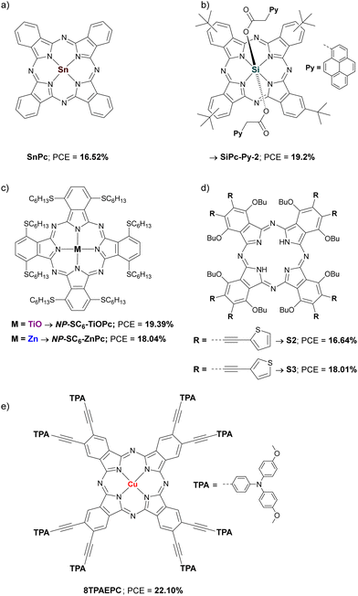 |
| | Fig. 14 Chemical structures of (a) SnPc, (b) SiPc-Py-2, (c) NP-SC6-TiOPc and NP-SC6-ZnPc, (d) S2 and S3 and (e) 8TPAEPC used as passivators and interlayers in PSCs and the PCE of the champion devices. | |
2.5. Phthalocyanines in other roles in PSCs
Apart from HTM, perovskite additive and interlayer, Pcs could be applied in other roles within PSCs,75 although only one relevant example has been found in the period studied. In that work, published in 2019 by He et al., the inclusion of CuPc (Fig. 4a and Table 5) in the carbon electrode of planar n–i–p PSCs is described. Carbon electrodes can replace gold in PSCs, being cheaper and providing greater long-term stability. However, they do not offer the same performances as gold, due to the energy level mismatch and the ineffective hole extraction at the carbon electrode/perovskite interface. That is why modifications are being investigated to improve these aspects. Devices with the architecture FTO/c-TiO2/Perovs./Carbon-CuPc (or Carbon) were fabricated, finding that the presence of CuPc improved the work function and the hole extraction of the carbon electrode. When CuPc was not included in the device, the PCE was 11.4% and, including CuPc as HTM, PCE was 12.8%, but when the carbon-CuPc electrode was used, PCE improved to 14.8%, still far from the traditionally used tandem spiro-OMeTAD/Au, with a 16.8% PCE. There are no stability studies in this article.76
2.6. Structure versus PCE properties in Pcs
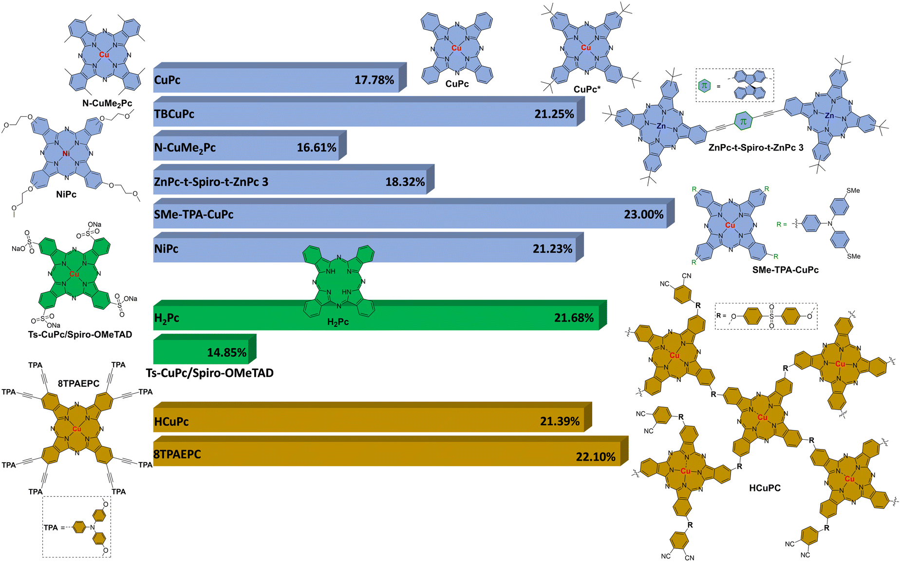
In Fig. 15 is represented a graphic with the structure of different Pcs and their best PCE value of each different section. As HTMs in n–i–p PSC devices: CuPc (17.78%) in non-substituted Pcs; TBCuPc (21.25%) in β-alkyl/aryl-substituted Pcs; N-CuMe2Pc (16.61%) in α-alkyl/aryl-substituted Pcs; ZnPc-t-Spiro-t-ZnPc 3 (18.32%) in Pc dimers; SMe-TPA-CuPc (23.00%) in amino-substituted Pcs; NiPc (21.23%) in alcoxy/phenoxy-substituted Pcs. As HTMs in p–i–n PSC devices: H2Pc (21.68%) in non-substituted Pcs; Ts-CuPc/Spiro-OMeTAD (14.85%) in substituted Pcs. As additives, passivating agents, and interlayers: HCuPc oligomer (21.39%); 8TPACEPc (22.10%). It is remarkable to conclude that CuPcs are outstanding versus the other Pcs probably due to their better mobility. The best PCE value obtained so far using Pcs, 23%, correspond to a metyltioltriphenylamine substituted CuPc (SMe-TPA-CuPc) used as HTM in a n–i–p PSC device.
 |
| | Fig. 15 Structure versus the best PCE value in Pcs as HTMs in n–i–p PSC devices (blue), as HTMs in i–n–p PSC devices (green) and as additives, passivating agents, and interlayers (brown). | |
3. Porphyrins in perovskite solar cells
Pors are macrocycles that can be found in nature playing different roles, for example, chlorophylls in photosynthetic systems. Structurally, consist of four pyrrole units linked via methine bridges (Fig. 16). From the point of view of applicability in different technologies, Pors have remarkable characteristics such as high molar absorptivity coefficients in the blue and the red region of the visible spectrum; customizable optoelectronic properties by straightforward synthetic modifications at the periphery (meso) and β-positions, and variations of the metal centre (Fig. 16); high air stability and robustness; good thermal stability; strong two-photon absorption; and efficient electron transfer. Some technologies in which Pors are applied are PDT, catalysis, and PVs, among others.77 Inside photovoltaic technologies, porphyrins have been widely applied in OSCs and DSSCs.78–80 A moderate number of articles can be found in which this type of material applied in PSCs is studied since 2019. The most common role in which Pors have been applied in PSCs is as HTM, but there are relevant works as additives and interlayers as well. In this part we will try to relate the molecular structure of the Pors with the performance presented by the PSCs in which they are included.
 |
| | Fig. 16 Chemical structure of a porphyrin with the indicated pyrrolic (β) and meso positions. M = H2 or a metal. | |
3.1. Porphyrins as HTM in PSCs
Donor–π–acceptor porphyrin systems have been used in dye-sensitized solar cells obtaining good efficiencies up to 13%.81 Following this idea, different tetrasubstituted donor–π–acceptor systems were tested in PSCs and, although the results have not been as good as expected, with maximums of 7%, this study contributed to the application of free porphyrins as HTM in PSCs.82 To increase the PCE value, the modification of donor–π–acceptor systems to donor–π–donor systems was made. This modification allows to increase the π–π stacking and to bring the HOMO level of the Por closer to the perovskite valence band.83 Within this type of porphyrin systems, we can find those functionalized in the meso-positions by arylamines, phenothiazine and alkyl anilines. As has been done in the case of Pcs, the works on Pors as HTMs that provided PCEs greater than 14% will be presented below.
3.1.1. Arylamine-substituted Pors.
In 2019, Shah et al. synthesized two new tetrakistriarylamine-Pors, one free (Po) and the other one with a cobalt central ion (CoP), and were applied as HTM in a p–i–n PSCs to study the effect of cobalt in the hole-extraction and the charge recombination at the perovskite-HTL interface (Fig. 17a). CoP exhibited a HOMO level (−5.30 eV) energetically favourable with the perovskite (−5.40 eV) and 0.27 eV deeper than the Po (−5.03 eV), improving the hole extraction and the electron blocking. In addition, XRD studies and SEM images evidenced that CoP enhance the formation of polycrystalline layers in the perovskite. Besides, CoP showed a contact angle with a water droplet of 98.4°, much higher than for Po (34.9°). As expected, CoP got a maximum of PCE higher than Po (16.9% vs. 14.5%; Table 6). Finally, before 120 h kept in dark, CoP provided greater stability.84
 |
| | Fig. 17 Chemical structures of arylamino-substituted Pors (a) Po, and CoP, (b) Y3, and (c) Y4 applied as HTMs in PSCs. | |
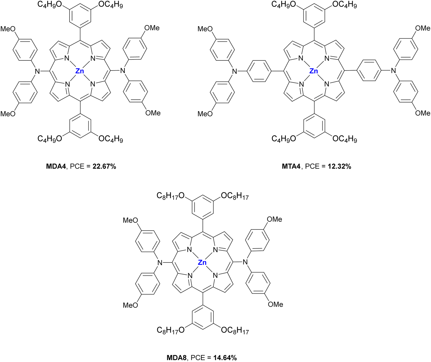
Table 6 Hole mobilities and HOMO levels of different Pors used as HTMs in PSCs, along with perovskite composition, device configuration and performances of the best devices
| HTMa |
μ
h (cm2 V−1 s−1) |
HOMO (eV) |
Perovskiteb |
Dopant |
Architecturec |
Thickness (nm) |
−Jsc (mA cm−2) |
V
oc (V) |
FF (%) |
PCE (%) |
Ref. |
|
The names of the HTMs are the same as in the original publications.
MA is methylammonium ([CH3NH3]+), FA is formamidinium ([CN2H5]+).
c is compact layer, m means mesoporous layer and CGC is carbon nanoparticle-graphene composite. — = not provided.
|
| Po |
1.0 × 10⁻⁴ |
−5.03 |
MAPbI3 |
No |
ITO/Por/Perovs./PCB61BM/Bathocuproine/Ag |
30 |
19.59 |
1.03 |
73.21 |
14.80 |
84
|
| CoP |
0.9 × 10⁻⁴ |
−5.30 |
MAPbI3 |
No |
ITO/Por/Perovs./PCB61BM/Bathocuproine/Ag |
30 |
21.81 |
1.04 |
74.55 |
16.91 |
84
|
| Y4 |
1.16 × 10⁻³ |
−5.28 |
(FA)0.85(MA)0.15Pb(I3)0.85(Br3)0.15 |
LiTFSI/TBP/FK209 |
FTO/c-TiO2/m-TiO2/Perovs./Por/Au |
100 |
20.13 |
1.01 |
0.79 |
16.05 |
85
|
|
MDA4
|
4.23 × 10⁻³ |
−5.13 |
FA0.8MA0.2PbI3 |
LiTFSI/TBP |
FTO/SnO2/Perovs./Por/Au |
60 |
24.56 |
1.14 |
81.30 |
22.67 |
86
|
|
MTA4
|
1.46 × 10⁻³ |
−5.34 |
FA0.8MA0.2PbI3 |
LiTFSI/TBP |
FTO/SnO2/Perovs./Por/Au |
60 |
23.50 |
0.98 |
53.52 |
12.32 |
86
|
|
MDA8
|
1.24 × 10⁻³ |
−5.16 |
FA0.8MA0.2PbI3 |
LiTFSI/TBP |
FTO/SnO2/Perovs./Por/Au |
60 |
23.50 |
0.96 |
64.96 |
14.64 |
86
|
|
YZT1
|
7.61 × 10⁻⁵ |
−5.23 |
Cs0.05[(FA0.83MA0.17)PbI0.83Br0.17]0.95 |
LiTFSI/TBP |
FTO/c-TiO2/m-TiO2/Perovs./Por/Au |
20–30 |
21.19 |
0.97 |
70.21 |
14.46 |
87
|
|
YZT2
|
2.69 × 10⁻⁵ |
−5.28 |
Cs0.05[(FA0.83MA0.17)PbI0.83Br0.17]0.95 |
LiTFSI/TBP |
FTO/c-TiO2/m-TiO2/Perovs./Por/Au |
20–30 |
11.86 |
0.93 |
52.77 |
5.81 |
87
|
|
YZT3
|
4.48 × 10⁻⁵ |
−5.34 |
Cs0.05[(FA0.83MA0.17)PbI0.83Br0.17]0.95 |
LiTFSI/TBP |
FTO/c-TiO2/m-TiO2/Perovs./Por/Au |
20–30 |
21.32 |
0.96 |
70.90 |
14.50 |
87
|
|
YZT4
|
5.48 × 10⁻⁵ |
−5.36 |
Cs0.05[(FA0.83MA0.17)PbI0.83Br0.17]0.95 |
LiTFSI/TBP |
FTO/c-TiO2/m-TiO2/Perovs./Por/Au |
20–30 |
21.40 |
0.95 |
73.51 |
14.95 |
87
|
|
ZnPy
|
— |
−5.35 |
MAPbI3 |
No |
FTO/c-TiO2/m-TiO2/Perovs./Por/Au |
— |
22.29 |
1.09 |
73.12 |
17.82 |
90
|
|
CuP
|
— |
−5.12 |
MAPbI3 |
No |
FTO/c-TiO2/m-TiO2/Perovs./Por/Au |
— |
22.57 |
1.10 |
73.34 |
18.21 |
93
|
Zhang et al. studied that same year the importance of the ligand conjugation and molecular packing between a ZnPor (Y4) and a disconnected porphyrin ring from the pyrroles at α-positions (Y3) (Fig. 17b). They conclude that the conjugated core Y4 increase the hole mobility and conductivity as macroscopic material in 3D n–i–p PSCs, much more than that for Y3 and, indeed, a greater PCE (16.05 vs. 0.01%) was achieved (Table 6). Stability tests showed that Y4 offers less stability than spiro-OMeTAD after 30 days in the dark at 25 and RH = 50%, which was attributed to the higher concentration of additives in the case of Y4.85 The effects of bulky donor groups at the meso-positions also have an important role when Pors are applied as HTMs in PSCs.
Recently, three D2h symmetric ZnPors (MDA4, MTA4 and MDA8) were synthesized by Mai et al. (Fig. 18). The donor–π–donor Pors consisted in two diarylamine or triarylamine groups, which allowed a favourable energy level alignment with the perovskite. These data were corroborated by optical, electrochemical, single-crystallography, and DFT calculations. MDA4-based PSCs showed the best PCE value of 22.67% (22.19% certified) (Table 6). The authors considered that the best photovoltaic parameters for MDA4 in comparison to MTA4 and MDA8 were since the triarylamine group gave a much lower HOMO for MTA4 that damage the hole extraction and the longer alkoxyl chains in MDA8 lead to pinhole-filled films and lower intermolecular interactions. Finally, ZnPors showed a great stability due to the hydrophobic character of alkoxyl chains. The hygrothermal stability of encapsulated device with MDA4 was performed at 60% RH and 60 °C in dark conditions retained 90% of initial PCE after 264 h. The photostability was also measured showing a retention of 93.9% of initial PCE after 200 h according to the ISOS-L-1 standard.86
 |
| | Fig. 18 Chemical structures of arylamino-substituted MDA4, MTA4 and MDA8 Pors applied as HTMs in PSCs. | |
3.1.2. Alkyl aniline-substituted Pors.
In 2020, Chou et al. demonstrated that novel push-push or push-pull Pors functionalized at 5,15-meso-positions can be used as HTMs with good cell performance in substitution of the benchmark spiro-OMeTAD. Thus, four alkyl 5,15-aniline-meso-substituted Pors were synthesized in a simple strategy with only two synthetic steps (YZT1, YZT2, YZT3, and YZT4; Fig. 19b). Theoretical studies and PL quenching experiments showed that there were different molecular packings induced by the alkyl chains for push–push and push–pull Pors with perovskite layer. Thus, the doped and non-doped Pors acting as HTMs showed similar values of PCEs than the spiro-OMeTAD (17.77%) (Fig. 19b and Table 6). Stability studies were carried out without dopants under the dark with RH 40% and showed that YZT4 retain 85% of the initial PCE after 340 h which is much better than that of spiro-OMeTAD.87
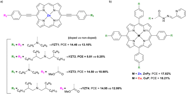 |
| | Fig. 19 Chemical structures of (a) aniline-substituted-Pors, and (b) acylhydrazone-substituted applied as HTMs is PSCs. | |
3.1.3. Acylhydrazone-substituted Pors.
In 2019, based in previous reports,88,89 a tetrasubstituted ZnPor (ZnPy) in the meso-positions with phenyl acylhydrazone was synthesized and used as HTM to prepare mesoporous n–i–p PSCs (Fig. 19c). N atoms from pyridine acted as Lewis bases and O and N atoms from acylhydrazone, linked the under-coordinated Pb atoms within the perovskite, so, passivating the defects sites and obtaining a power conversion efficiency up to 17.82% (Table 6). At the same time, the devices including ZnPy showed a contact angles of water droplets around 107° compared to 80° in the case of spiro-OMeTAD, providing greater stability of the device against moisture at room temperature with RH of 70% and a thermal stability at 85 °C in N2 atmosphere keeping almost all the original PCE after 100 h.90 One year later, inspired by blue copper proteins, since the redox couple Cu(I)/Cu(II) has a high self-exchange rate for electron transfer,91,92 Si et al. synthesized a new CuPor (CuP) with acylhydrazone groups (Fig. 19c) for its application in mesoporous n–i–p PSCs as HTM. Devices including CuP reached a maximum PCE of 18.21% compared with the PCE of ZnPy (17.8%). The thermal stability at 85 °C in N2 atmosphere of these new devices with CuP as HTM also exceeded that of the spiro-OMeTAD-based PSCs.93
3.2. Porphyrins as perovskite additives
Different studies indicate that the formation of defects at perovskite layers and grain boundaries by the iodide or ammonium ions cause the instability of PSCs. For example, under high heat and/or moisture, methylammonium ions (MA+) can be released from the perovskite lattice generating under-coordinated Pb and Pb-I antisite defects.94,95 To avoid this, several additives were used to modify the perovskite film.96–99
3.2.1. Eu-Por in 2D/3D PSCs.
Feng et al. fabricated a new Eu-porphyrin (Eu-pyP; Fig. 20a) and applied it as additive in the fabrication of mesoporous n–i–p PSC. This rare-earth ion was chosen because of its charge-transfer absorption band in the UV region, and its emission spectra mainly located in the visible region.100 A value of 18.35% PCE (Table 7) was obtained and, although it was slightly less than the reference one, that is, without Eu-pyP as additive (18.96%), the stability from moisture, heat and light was improved (85 °C, 45% RH, AM 1.5G). Finally, authors also demonstrated by XRD spectra that Eu-pyP can achieve the self-repairing process due to the decrease of PbI2 in the 0.5% Eu-pyP doped PSCs.101
 |
| | Fig. 20 Chemical structure of Pors (a) Eu-pyP, (b) ZnP, (c) ZnP, NiP, CuP-S1 and CuP-S2, (d) YD2-o-C8, (e) ZnPP, (f) ZnTFP-DPP, (g) FPD, and (f) Ni-P applied as additives in PSCs. | |
Table 7 Hole mobilities and HOMO levels of different Pors used as additives in PSCs, along with perovskite composition, device configuration and performances of the best devices
| Additivesa |
μ
h (cm2 V−1 s−1) |
HOMO (eV) |
Perovskiteb |
Dopant |
Architecturec |
Wt % |
−JSC (mA cm−2) |
V
oc (V) |
FF (%) |
PCE (%) |
Ref. |
|
The names of the additives are the same as in the original publications.
MA is methylammonium ([CH3NH3]+), FA is formamidinium ([CN2H5]+).
c is compact layer and m means mesoporous layer, EA is OCH2CH2NH3, PEI is poly(ethylene imine). — = not provided.
|
| Eu-pyP |
— |
— |
MAPbI3 |
No |
FTO/c-TiO2/m-TiO2/Perovs.-Por/HTL/Au |
— |
22.68 |
1.08 |
74.92 |
18.35 |
101
|
| ZnP-NH3 |
— |
— |
MAPbI3 |
No |
FTO/c-TiO2/m-TiO2/Perovs.-Por/HTL/Au |
0.05 |
23.27 |
1.12 |
77.63 |
20.46 |
102
|
| ZnP |
— |
— |
MAPbI3 |
No |
FTO/m-TiO2/Perovs.-Por/HTL/Au |
0.05 |
23.23 |
1.11 |
77.41 |
20.01 |
103
|
| NiP |
3.75 × 10⁻⁴ |
— |
Cs0.05Rb0.05(FA0.83MA0.17)0.90Pb(I0.95Br0.05)3 |
LiTFSI/TBP |
FTO/ZnO-MgO-EA+/m-TiO2/Perovs.-Por/HTL/Au |
0.5 |
25.49 |
1.17 |
81.01 |
24.16 |
104
|
| CuP-S1 |
2.05 × 10⁻⁴ |
— |
Cs0.05Rb0.05(FA0.83MA0.17)0.90Pb(I0.95Br0.05)3 |
LiTFSI/TBP |
FTO/TiO2/Perovs.-Por/HTL/Au |
— |
24.12 |
1.12 |
75.13 |
20.29 |
105
|
| CuP-S2 |
5.49 × 10⁻⁴ |
— |
Cs0.05Rb0.05(FA0.83MA0.17)0.90Pb(I0.95Br0.05)3 |
LiTFSI/TBP |
FTO/TiO2/Perovs.-Por/HTL/Au |
— |
25.45 |
1.16 |
82.11 |
24.15 |
105
|
| YD2-o-C8 |
— |
−5.21 |
CsFAMA |
LiTFSI/TBP |
ITO/SnO2/Perovs.-Por/HTL/Au |
0.05 mg mL−1 |
24.40 |
1.05 |
80.00 |
20.50 |
108
|
| ZnPP |
— |
— |
— |
LiTFSI/TBP |
FTO/SnO2/Perovs.-Por/HTL/Ag |
0.05 mg mL−1 |
22.57 |
1.13 |
82.91 |
21.08 |
109
|
| ZnTFP-DPP |
3.75 × 10⁻² |
−5.36 |
MAPbI3 |
No |
ITO/SnO2/Perovs.-Por/HTL/Au |
0.10 |
24.30 |
1.08 |
75.00 |
19.30 |
110
|
| FPD |
— |
— |
— |
LiTFSI/TBP |
ITO/SnO2/Perovs.-Por/HTL/Ag |
— |
25.19 |
1.13 |
80.86 |
23.00 |
111
|
| Ni-P |
— |
— |
FASnI3 |
No |
ITO/PEDOT:PSS/Perovs.-Por/PCBM/PEI/Ag |
0.02 |
20.72 |
0.62 |
68.73 |
8.86 |
112
|
3.2.2. Monoammonium and monoamine Pors.
In 2019, the Cao's group published a monoammonium ZnPor (ZnP; Fig. 20b) that was determined to anchor on the perovskite surface and avoid the cationic escape reducing the defects formation, i.e. constructing a molecular encapsulation and surface passivation of perovskite layer. Additionally, by introducing this additive, it was possible to fabricate devices with a large surface area (16 cm2) and it was obtained an unprecedent high value of 18.26% PCE with a large-area of 1.96 cm2, while the value for the small-area (0.1 cm2) was 20.46% (Table 7). Additionally, the ZnPor-based PSCs showed a significant moisture and thermal stability retaining 90% of its initial PCE over 1000 hours at 85 °C with 45% RH, while the control PSCs failed under 300 h.102
Cao and co-workers published three articles with several porphyrins able to react with the organic ions in the perovskite to yield monoammonium MPors (Fig. 20c). These protonated MPors can passivate defects increasing the hole transport within perovskite lattice and enabling their use in the fabrication of large area PSCs. In the first one, when ZnPor (ZnP; Fig. 20c) was used, there was no escape of iodide from solutions indicating that the monoammonium ZnPor (ZnPor-H+) was linked to the surface and the grain boundaries of the perovskite film to retard ion migration. It was obtained a good PCE of 19.01% in the blade-coating large-area PSCs (1.96 cm2) and a 20.01% PCE for small-area PSCs (0.1 cm2). Furthermore, after treating the ZnP-doped perovskite film with ZnP crystals it was achieved a 1D coordination polymer with a great charge extraction and an excellent 20.01% of PCE (Table 7). This coordination polymer also improved thermal and moisture stability. 0.05% ZnP-polymer based films kept over 90% of its initial PCE after 6000 h in the humidity of 45% compared with pure perovskite that failed after 5000 h. Regarding thermal and photostabilities at 85 °C in N2 atmosphere or AM 1.5G continuous illumination, ZnP-polymer remain over 90% of its initial PCE over 2000 h, while control PSCs failed after 600 h.103 In the following work, five MPors were synthesize (M = Co, Ni, Cu, Zn and H) and added into a perovskite precursor solution to passivate perovskite grain layer and realize the efficient hole extraction. Only in the case of NiP (Fig. 20c), a strong dipole moment was detected for NiP-H+ along the direction of the ammonium side chain and polarons were obtained periodically, causing passivation of defects. The best PCE was up to 24.16% (23.70% certified; Table 7) with a small area (0.096 cm2). Regarding large area PSCs (1.0 cm2), the best PCE value was 22.81% (22.10% certified). The values were remained stable retaining 90% of initial PCE after 5000 h at room temperature and 3000 h at 85 °C, while control PSC without NiP maintained only less than 10% of initial PCE value at the same conditions.104 In the last research work, two types of supramolecular ordering (namely CuP-S1 and CuP-S2; Fig. 20c) were studied after doping the perovskite layer with a monoamine CuPor to investigate the effects of different intermolecular interactions. By post-annealing treatment at 120 °C for 24 h, CuP-S1 was transformed into CuP-S2 changing the π–π stacking interaction on the Pors backbones. Crystal structures and theoretical data for CuP-S2 revealed a stronger interaction between the amine units and the central Cu atoms in the neighbouring Pors. Photovoltaics parameters confirmed that the formation of homogeneously large polarons in CuP-S2 increased the charge transport and hole extraction increasing the PCE values from 20.29% to 24.15 for CuP-S1 and CuP-S2, respectively (Table 7). Stability studies also confirmed that both, CuP-S1 and CuP-S2, maintained 90% of the initial PCE value at room temperature and at 85 °C, with high humidity, after more than 3000 hours. On the contrary, the reference PSCs devices almost completely failed in the stability tests.105
3.2.3. Donor–π–acceptor type Pors.
Two donor–π–acceptor-type ZnPors were studied as additives whose structure included a carboxylic acid (YD2-o-C8; Fig. 20d) or pyridines (ZnPP; Fig. 20e) in planar n–i–p PSCs. These functional groups should interact with uncoordinated Pb2+ and donor groups to tailor the electron density distribution in the acceptor groups and increase the anchorage to Pb2+ cations.106,107 ZnPors were incorporated during the antisolvent treatment process and checked by X-ray photoelectron spectroscopy (XPS) measurements on the perovskite films. It was proven that YD2-o-C8 helped to obtain a better morphology and crystallinity in the perovskite layer and a proper energy alignment for the charge extraction, obtaining a PCE of 20.50% (Table 7). Moreover, alkyl chains increased the hydrophobicity helping to retain 93% the stability of the devices under dark conditions for 30 days (25–40 °C, 20–40% RH).108 The ZnPP also increase the quality of perovskite layer reducing the trap density and achieving a PCE of 21.08% with an FF as high as 82.91% (Table 7). The stability tests of unencapsulated devices showed a retention of 98% PCE after 1000 h with 50% RH.109 Zheng et al. synthesized a conjugated antiaromatic donor–acceptor type Por-diketopyrrolopyrrole (ZnTFP-DPP; Fig. 20f) to apply as a light absorber additive in planar n–i–p PSCs. Compared with a classical aromatic Por, antiaromatic ZnTFP-DPP showed a higher HOMO level, a narrower bandgap, and more red-shifted light absorption. According to the authors, the diketopyrrolopyrrole (DPP) moiety allowed to obtain a better alignment of the HOMO energy level and an increase of the light absorption. With this new features, ZnTFP-DPP-based devices exhibited a maximum PCE of 19.30% versus 18.4% for reference PSCs, mainly due to Jsc (24.30 mA cm−2) enhancement compared with the non-additive reference one (22.7 mA cm−2; Table 7). There are no stability studies in this article.110 Finally, in 2022, a fullerene-Por dyad (FPD; Fig. 20g) was synthesized by Liang et al. and incorporated as additive into planar n–i–p PSCs. The fullerene had the capability to interact with the iodide ions, the Por showed excellent passivation and stability effects and the fluorine, and the ester groups could interact with hydrogen and lead atoms also passivating the defects and enhancing the stability. FPD showed an improvement efficiency of 23% (Table 7) compared to the control device (20.99%). Moreover, the FPD-modified PSC exhibited an improved stability, retaining more than 83% PCE after 1500 h of MPPT. Finally, as an additional benefit, it was observed an in-situ sedimentation of a water-insoluble FPD-Pb complex, which could prevent the dreaded lead contamination.111
3.2.4. NiPor in Sn-based PSCs.
Guo et al. added a NiPor (Ni-P; Fig. 20h) into the perovskite precursor to improve the crystallization of lead-free FASI3-based p–i–n PSCs. The ester group in Ni-P was chosen to bind with SnI2 and restrain nucleation. As a result, a delay of crystallization was observed, improving the PCE from 6.18% without Por to 8.86% with Ni-P (Table 7). Furthermore, electronic cloud of Ni-P provided antioxidative properties which protect the perovskite layer from degradation. Additionally, PSCs retained 80% of PCE after 300 h under air environment and 75% of PCE after 40 h under 1 sun irradiation.112
3.3. Porphyrins as interlayers in PSCs
3.3.1. MnPors.
In 2020, Gkini et al. used a tetrasubstituted methylpyridine-MnPor ((TMePyP)I4Mn(AcO); Fig. 21a) in a n–i–p planar PSCs. The MnPor was introduced between the TiO2 electron transport layer and the perovskite absorber to act as an electron transport mediator. The researchers demonstrated that MnPor created a hydrophobic environment and improved the growth of a homogeneous and crystallized perovskite layer. Moreover, a decrease in the work function of TiO2 was measured since Mn2+ could introduce into the interstices of perovskite to limit the generation of defects.113,114 PCE values showed an increase of 22% compared with reference one and a final value of 18.70% (Table 8). Finally, stability studies were carried out, retaining 75% of initial PCE value after 1000 hours under dark and 20% of humidity.115
 |
| | Fig. 21 Chemical structure of Pors (a) (TMePyP)I4Mn(AcO), (b) ZnPy-NH3Br, (c) Co(II)P, (d) CuP 1, (e) CuP 2, and (f) Cu-Por used as interlayers in PSCs. | |
Table 8 HOMO levels of different Pors used as interlayers in PSCs, along with perovskite composition, device configuration and performances of the best devices
| Interlayersa |
HOMO (eV) |
Perovskiteb |
Dopant |
Architecturec |
Thickness |
−Jsc (mA cm−2) |
V
oc (V) |
FF (%) |
PCE (%) |
Ref. |
|
The names of the interlayers are the same as in the original publications.
MA is methylammonium ([CH3NH3]+), FA is formamidinium ([CN2H5]+).
c is compact layer, m means mesoporous layer, EA is OCH2CH2NH3 and QDs is quantum dots.
Obtained from DFT studies at the B3LYP, 6-31G(d,p) level in vacuum.
The value of x is not clarified in the original work.
Thickness for perovskite and Por. — = not provided.
|
| (TMePyP)I4Mn(AcO) |
— |
MAPbI3 |
LiTFSI/TBP/FK209 |
FTO/TiO2/Por/Perovs./HTL/Ag |
70 nm |
23.52 |
1.04 |
75.00 |
18.70 |
115
|
| ZnPy-NH3Br |
— |
CsMAFA |
LiTFSI/TBP |
FTO/ZnO-MgO-EA+/Perovs./CsPbBr3 QDs-Por/HTL/Au |
60 nm |
23.91 |
1.10 |
76.17 |
20.02 |
120
|
|
Co(II)P
|
— |
Cs0.05(MA0.17FA0.83)(100−x)Pb(I0.83Br0.17)3e |
LiTFSI/TBP |
FTO/c-TiO2/m-TiO2/Perovs./Por/HTL/Au |
10 nm |
23.45 |
1.14 |
78.97 |
21.28 |
121
|
|
CuP 1
|
−5.05 |
Cs0.05(MA0.17FA0.83)0.95Pb(I0.83Br0.17)3 |
LiTFSI/TBP |
FTO/c-TiO2/m-TiO2/Perovs./Por/HTL/Au |
6.11 nm |
23.64 |
1.11 |
78.87 |
20.71 |
122
|
|
CuP 2
|
−4.96 |
Cs0.05(MA0.17FA0.83)0.95Pb(I0.83Br0.17)3 |
LiTFSI/TBP |
FTO/c-TiO2/m-TiO2/Perovs./Por/HTL/Au |
5.67 nm |
23.27 |
1.13 |
79.63 |
20.97 |
123
|
|
Cu-Por
|
−4.96 |
— |
No |
FTO/c-TiO2/m-TiO2/Perovs./Por/HTL/Au |
— |
23.76 |
1.13 |
79.11 |
21.24 |
124
|
|
BZnTPP
|
−5.96d |
MAPbI3 |
No |
FTO/TiO2/Por/Perovs./HTL/Ag |
— |
21.11 |
1.11 |
74.00 |
17.34 |
125
|
|
Cs0
|
−5.28 |
FA0.8MA0.2PbI3 |
LiTFSI/TBP |
FTO/SnO2/Perovs./Por/HTL/Au |
670 nmf |
23.96 |
1.10 |
84.30 |
22.14 |
126
|
|
Cs1
|
−5.27 |
FA0.8MA0.2PbI3 |
LiTFSI/TBP |
FTO/SnO2/Perovs./Por/HTL/Au |
670 nmf |
24.14 |
1.10 |
84.20 |
22.37 |
126
|
|
Cs2
|
−5.35 |
FA0.8MA0.2PbI3 |
LiTFSI/TBP |
FTO/SnO2/Perovs./Por/HTL/Au |
670 nmf |
23.74 |
1.12 |
83.60 |
22.17 |
126
|
|
Por-BTA
|
−5.53 |
FAMAPbI |
LiTFSI/TBP/FK209 |
FTO/SnO2/Perovs./Por/HTL/Au |
— |
25.22 |
1.01 |
80.38 |
22.30 |
127
|
|
CuTPPS4
|
−5.20 |
— |
No |
ITO/PEDOT:PSS/Por/Perovs./PCBM/Bathocuproine/Al |
— |
20.42 |
0.94 |
75.91 |
14.61 |
128
|
|
ZnP
|
−4.77 |
Cs0.05(MA0.17FA0.83)(100−x)Pb(I0.83Br0.17)3e |
LiTFSI/TBP |
FTO/ZnO-MgO-EA+/m-TiO2/Perovs./Por/HTL/Au |
5.48 nmf |
23.19 |
1.11 |
79.29 |
20.53 |
129
|
3.3.2. Diammonium and diamine Pors.
CsPbBr3 quantum dots (QDs) have been used in several studies between the perovskite layer and the HTL to avoid the charge recombination, improve the ion migration and passivate the defects.116–118 However, passivated organic ligands used to anchor QDs to the perovskite film are inconvenient to charge transport.119 To improve the conductivity Feng et al. employed a diammonium ZnPor salt (ZnPy-NH3Br; Fig. 21b) as an interlayer to treat the zero-dimensional CsPbBr3 QDs structure on a Cs-based perovskite layer. The ZnPy-NH3Br was able to enhance the PCE up to 20.02% from the 19.12% based on pure perovskite and 19.50% based on QDs-perovskite (Table 8). Furthermore, the new device maintained 85% of initial efficiency after 450 h.120 Xiao et al. used a diamine CoPor (Co(II)P; Fig. 21c) as interlayer between perovskite film and the HTM to construct in situ a Co(II)P-based coordination polymer on the perovskite layer. In this polymer, two amino groups were coordinated with a central cobalt from a different molecule establishing a three-dimensional structure. The new generated polymer with Co(II) was able to reduce the liberated I2 in the perovskite to I− and cause its regeneration. Last, the Co(II)/Co(III) redox pair in the polymer afforded an effective charge transport, increasing the PCE up to 21.28% (Table 8). Regarding the stability, with the humidity of 45%, the device maintained more than 90% of the original PCE after 3000 h. Moreover, at 85 °C and AM 1.5G illumination under N2 atmosphere retained 90% of the initial PCE after 2000 h, whereas the control PSC failed at the same time in both cases.121
3.3.3. Thiol CuPors.
In 2021, Yan et al. designed a molecular modification of the perovskite film using a tetra-thiol CuPor (CuP 1; Fig. 21d). The thiol was chosen to passivate the perovskite through the coordination of Pb2+ and prevent the lead leakage. DFT calculation also showed that CuP 1 can achieve the effective fixation of I− and I2. The best PCE value was enhanced up to 20.71% (Table 8). Furthermore, CuP 1 was able to produce an effective encapsulation of the perovskite film improving the device stability. The devices showed a retain of 90% of the initial PCE after 2000 h and 45% RH and over 90% after 1000 h at 85 °C. The photostability was also measured at AM 1.5G illumination in N2 atmosphere remained 90% after 1000 h, whereas the control devices lost the initial performance after this time.122 A few months later, Xiao et al. developed a similar strategy using a thiol CuPor (CuP 2; Fig. 21e). They observed the same coordination effect between the thiol group and Pb2+ and an efficient tuning of the electron distribution of porphyrin π ring due to the Cu(II) ions, reducing the defects caused by the I− and I2 leakage. Finally, CuP 2 gave the best PCE of 21.76% (certified 20.97%; Table 8). Regarding the stability, at 45% RH and after 3000 h, CuP 2 retained 90% of the original PCE. They also measured the thermal and photostability. In the first case, at 85 °C in N2 atmosphere, the devices with CuP 2 preserved 90% of initial PCE after 2000 h. In the second case, measurements were carried out at the AM 1.5G illumination in N2 atmosphere showing a retention of 90% of initial PCE after 1000 min.123 The last research so far using thiol-CuPor was made by Li et al. with a secondary amine group (Cu-Por; Fig. 21f). IR experiments confirmed the presence of hydrogen-bonds between the side chain N–H group in Cu-Por with I− and I2. This extra interaction allowed to increase the PCE value up to 21.24% (Table 8). The new Cu-Por-based devices without encapsulation retained 90% of the initial PCE after 2000 h at the illumination of AM 1.5G and after 2200 h at 85 °C, in N2 atmosphere.124
3.3.4. Donor–π–acceptor type ZnPors.
Different donor–π–acceptor porphyrins have been used as interlayers in PSCs. The first example is formed by a ZnPor-bodipy (BZnTPP; Fig. 22a) and it was implemented as electron transfer mediator from the perovskite film to the TiO2. The “push-pull” character of BZnTPP enhanced the PCE values from 16.63% to a maximum of 17.34% (Table 8). Finally, the stability of unencapsulated BZnTPP-based PSCs was measured. At room temperature and 40% HR, the devices with BZnTPP retained 85% of the initial PCE after 26 days compared to 61% in the reference cell.125 The second example consists in three ZnPors each formed by two octyloxi groups, one in front of the other, a diphenylamine group as electron donor and cyanoacrylic acid as electron acceptor. Moreover, last two group is separated from the ZnPor ring by a different π-bridge: phenylene, thiophenylene and dithiophenylene (CS0, CS1 and CS2, respectively; Fig. 22b). The ZnPors were located between perovskite film and HTM to act as a passivators and reduce the defects caused by Pb2+ cations. The best PCEs values improved from 21.04% for the control one to 22.14% CS0, 22.37% CS1 and 22.17% CS2 (Table 8). It was measured the long-term stability of the ZnPor-modified devices without encapsulation at room temperature and under 30% RH and the modified devices retained more than 90% of their initial PCEs after 50 days.126
 |
| | Fig. 22 Chemical structure of Pors (a) BZnTPP, (b) Cs0, Cs1 and Cs2, (c) Por-BTA, (d) MTPPS4, and (e) ZnP used as interlayers in PSCs. | |
3.3.5. Other Pors.
A free porphyrin-involved benzene-1,3,5-tricarboxamide dendrimer (Por-BTA; Fig. 22c) was synthesized and applied, for the first time, as interface material between the perovskite and the HTL in PSCs. The structure showed not only a strong tendency to self-assemble providing a channel for hole transport, but also carbonyl units were able to passivate defects in the perovskite surface through coordination with Pb2+ cations. It was obtained an improved PCE of 22.30% (Table 8). Finally, unencapsulated PSCs of Por-BTA-treated devices retained 66% of its initial PCE after 45 days at 20 °C and 50–60% RH while that the control PSC dropped to 17%.127 In 2020, a series of metallic porphyrins were inserted as interlayers between PEDOT:PSS and perovskite layer in an inverted PSCs (Fig. 22d). The different MPors not only changed the HOMO-LUMO levels to get closer to this of perovskite but also promoted the hole extraction. The best PCE value was obtained with CuTPPS4 (14.61%; Table 8) compared with 11.65% from the control device, but they were not as high as other publications. This fact was explained due to the orientation of interfacial MPor in which the ring was parallel to the ITO surface and the thickness of porphyrin. There are no stability studies in this article.128 Liang et al. employed an acryloyl ZnPor (ZnP, Fig. 22e) to its in situ polymerization on the perovskite surface through thermal procedure confirmed by FTIR spectroscopy. Moreover, UV-vis analysis suggested that the carbonyl groups were able to fix Pb2+ cations into the perovskite and avoided the non-radiative recombination. The photovoltaic performance was measured obtaining a maximum PCE value of 20.53% (Table 8). Finally, thermal stability studies confirmed that ZnP-polymer-based devices retained 77% of PCE after 900 hours at 85 °C, while light stability studies retained 86% after 630 h at AM 1.5G.129
3.4. Structure versus PCE properties in Pors
In Fig. 23 is represented a graphic with the structure and the best PCE value of each different section. As HTMs in PSC devices: MDA4 (22.67%) in arylamine-substituted Pors. As additives: CuP-S2 (24.16%) in amino Pors. As interlayers: Cs1 (22.37%) in donor–π–acceptor type ZnPors. Although ZnPors are the most study systems with very impressive numbers, the use of arylamino substituted CuPors as additive is the best PCE value, 24.16%, obtained in Pors systems.
 |
| | Fig. 23 Structure versus the best PCE performance in Pors as HTM (MDA4), as additives (CuP-S2) and as interlayer (Cs1). | |
4. Other porphyrinoids in perovskite solar cells
In addition to Pcs and Pors, the porphyrinoid family has more members that were incorporated into PSCs. In this section, the works that study tetrabenzotriazacorroles (TBC) and subphthalocyanines (SubPc) will be presented. These materials also have excellent chemical and thermal stability, as well as great chemical versatility, which allows their optoelectronic properties to be tuned.
On the one hand, TBC, also known as tetrabenzocorroles, triazatetrabenzocorroles and tetrabenzocorrolazines, are macrocycles that belong to the families of porphyrins, phthalocyanines, and corroles, and are structurally like Pcs that have lost a meso-nitrogen (Fig. 24a and b). Due to π-contraction, the TBC macrocycle is somewhat twisted. So that, they have unique optoelectronic properties, for instance, while Pcs absorb weakly in the blue region, TBCs do so strongly. Like Pcs, TBCs may (Fig. 24b) or may not (Fig. 24a) coordinate an atom in the center of the ring.130 On the other hand, subphthalocyanines (Fig. 24c) are aromatic chromophores with 14 delocalized π-electrons in their central ring, with a central boron atom coordinated. These porphyrinoids are not flat either, since they have a concave structure, which prevents their excessive aggregation even in the solid state.
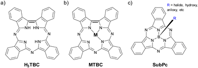 |
| | Fig. 24 General chemical structures of (a) H3TBC, (b) MTBC, and (c) SubPc. | |
4.1. Tetrabenzotriazacorroles
Two articles on TBCs as HTM can be found, both published in 2020. In these works, both the optoelectronic and photovoltaic properties of TBCs and their precursor Pcs are compared. In the first one, Zhang et al., described the synthesis, characterization, and PV properties as dopant-free HTMs in 3D n–i–p PSCs of three TBCs, TBC-1, TBC-2, and TBC-3, compared to the β-tetraphenoxy Pc (H2Pc-1, precursor of TBC-2) and undoped spiro-OMeTAD (Fig. 25a and Table 9). Compared to its Pc counterpart and spiro-OMeTAD, all TBCs had higher hole transport mobility, broader light absorption, and shallower HOMOs and LUMOs. The α-substituted TBC-1 provided the best performance, with 16.2% PCE, whereas the poorest results were obtained with unsubstituted TBC-3 (PCE = 6.8%) and H2Pc-1 (PCE = 8.7%). For its part, β-substituted TBC-2 was like undoped spiro-OMeTAD (11.4% vs. 11.2% PCE). The authors attribute these results to the greater hole mobility and the more intense absorption of TBC-1 compared to the other materials. Stability tests revealed that TBC-1 conferred greater stability to PSCs than TBC-2, H2-Pc-1 and spiro-OMeTAD, retaining 84% of the initial PCE after 30 days storage in a nitrogen glove box.131 Lu and Zhang studied tetra(4-tert-butyl phenoxy)-tetrabenzocorrolazine phosphorous POTBC(β-OPB)4 (Fig. 25b and Table 9) as dopant-free HTM in 3D n–i–p PSCs, comparing it with its precursor H2Pc(β-OPB)4 and undoped spiro-OMeTAD. Whilst Pc and TBC provided similar efficiencies; 15.6% and 15.8% PCE, respectively; undoped spiro-OMeTAD resulted in a PCE of 10.8%. Besides, POTBC(β-OPB)4 provided better stability than spiro-OMeTAD under 1 sun illumination in air for 500 hours under maximum MPPT conditions, retaining more than 80% of the initial PCE. In this work, fluorescence properties and singlet oxygen formation, among others, were also studied.132
 |
| | Fig. 25 Chemical structures of Pors (a) TBC-1, TBC-2 and TBC-3, and (b) POTBC(β-OPB)4 applied as HTMs in PSCs. | |
Table 9 Parameters of porphyrinoids used in different roles in PSCs, along with perovskite composition, device configuration and maximum performances under reverse scan of the best devices
| Porphinoida |
Role |
μ (cm2 V−1 s−1) |
LUMO (eV) |
HOMO (eV) |
Perovskiteb |
Architecture |
Thickness |
wt% |
−Jsc (mA cm−2) |
V
oc (V) |
FF (%) |
PCE (%) |
Ref. |
|
The names of the compounds are the same as in the original publications.
MA is methylammonium ([CH3NH3]+), FA is formamidinium ([CN2H5]+).
The value or meaning of x is not clarified in the original work.
Measured under forward scan.
|
| TBC-1 |
HTM |
1.35 × 10⁻³ |
−3.35 |
−5.11 |
MAPbI3 |
FTO/c-TiO2/m-TiO2/Perovs./TBC/Au |
103 nm |
— |
24.50 |
1.01 |
65.1 |
16.2 |
131
|
| TBC-2 |
HTM |
1.14 × 10⁻³ |
−3.37 |
−5.12 |
MAPbI3 |
FTO/c-TiO2/m-TiO2/Perovs./TBC/Au |
— |
— |
21.80 |
0.90 |
57.9 |
11.4 |
131
|
| TBC-3 |
HTM |
— |
−3.22 |
−5.10 |
MAPbI3 |
FTO/c-TiO2/m-TiO2/Perovs./TBC/Au |
— |
— |
21.10 |
0.68 |
37.9 |
6.8 |
131
|
| POTBC(β-OPB)4 |
HTM |
1.23 × 10⁻³ |
— |
— |
MAPbX3c |
FTO/c-TiO2/m-TiO2/Perovs./TBC/Au |
105 nm |
— |
23.70 |
0.94 |
70.97 |
15.8 |
132
|
| OPh,I-SubPc |
Additive |
— |
— |
— |
— |
ITO/c-TiO2/m-TiO2/Perovs.-SubPc/HTM/Au |
— |
0.65 |
3.03 |
0.581 |
53.7 |
0.9 |
135
|
| Cl6SubPc |
ETM |
— |
−3.84 |
−6.04 |
Csx(FA0.85MA0.15)1−xPb(I0.85Br0.15)3c |
ITO/Cu:NiOx/Perovs./SubPc-C60/BCP/Ag |
8 nm |
— |
23.31 |
1.16 |
81.2 |
22.0 |
136
|
| Cl-SubPcCl6 |
ETM |
— |
−3.84 |
−6.04 |
CsFAMAPbIBr |
FTO/NiOx/PTAA/Perovs./PEAI/SubPc/BCP/Cr/Au |
2 nm |
— |
17.38d |
0.987d |
63.1d |
10.8d |
137
|
| F-SubPcCl6 |
ETM |
— |
−3.84 |
−6.04 |
CsFAMAPbIBr |
FTO/NiOx/PTAA/Perovs./PEAI/SubPc/BCP/Cr/Au |
2 nm |
— |
17.00d |
0.996d |
61.0d |
10.3d |
137
|
|
Cl-SubPcF6
|
ETM |
— |
−3.84 |
−6.07 |
[(FAPbI3)0.87(MAPbBr3)0.13]0.92(CsPbI3)0.08 |
FTO/NiOx/PTAA/Perovs./PEAI/SubPc/C60/BCP/Cr/Au |
0.5 nm |
— |
20.47d |
1.006d |
66.0d |
13.6d |
138
|
|
Cl-SubPcF12
|
ETM |
— |
−4.19 |
−6.34 |
[(FAPbI3)0.87(MAPbBr3)0.13]0.92(CsPbI3)0.08 |
FTO/NiOx/PTAA/Perovs./PEAI/SubPc/C60/BCP/Cr/Au |
2 nm |
— |
18.94d |
0.920d |
57.0d |
9.9d |
138
|
|
Cl-SubPcCl12
|
ETM |
— |
−4.18 |
−6.28 |
[(FAPbI3)0.87(MAPbBr3)0.13]0.92(CsPbI3)0.08 |
FTO/NiOx/PTAA/Perovs./PEAI/SubPc/C60/BCP/Cr/Au |
2 nm |
— |
19.75d |
0.920d |
60.0d |
10.9d |
138
|
4.2. Subphthalocyanines
Few examples of SubPcs as components of PSCs can be found in the literature, mainly on SubPcs as HTMs whose results were modest.133,134 In 2021, three interesting studies were published describing the incorporation of SubPcs with different roles in PSCs. In the first of them, García-Aboal et al. studied OPh,I-SubPc (Fig. 26a and Table 9) as perovskite additive in 3D n–i–p devices. When the SubPc was added in the proper proportion (0.65% wt), it is capable of being incorporated into the 3D/2D interlayer, enhancing the photoresponse of the hybrid bromide perovskites because OPh,I-SubPc acted as another harvesting unit. Although this approach was novel, the maximum PCE achieved was 0.9%.135 Chen et al. incorporated Cl6SubPc (Fig. 26b and Table 9) in a doble ETL along with C60 in p–i–n PSCs. This double ETL, composed of 8 nm of Cl6SubPc and 20 nm of C60, was deposited under vacuum. The presence of Cl6SubPc, not only passivated interfacial defects by robust Cl-Pb bonds, but also suppressed iodide diffusion since it has strong interactions with iodine. After device optimization, a PCE of 22.0% (certified 21.3%) was reached with a negligible hysteresis behavior. Differently, when only C60 or only Cl6SubPc was used as ETL, the reached PCEs were 20.82% or 20.5%, respectively. Additionally, devices that included double ETL Cl6SubPc/C60 showed unprecedented long-term stability, retaining 95% of PCE over 1200 h of outdoor testing, 90% of PCE under illumination and MPPT for over 2000 h.136 Labella et al. published a similar work, in which they used SubPc-based ETLs in two types of inverted p–i–n PSCs In this study they compared F-SubPcCl6 and Cl-SubPcCl6 (Fig. 26c and Table 9) to C60. Although Cl-SubPcCl6 was better than F-SubPcCl6, when SubPc under study were included, the general performance of the devices worsened, including the long-term stability. The best PCEs reached were 10.8%, 10.3% and 13.0% with Cl-SubPcCl6, F-SubPcCl6 and C60 under forward scan, respectively.137 In a more recent study, this same group applied the SubPcs Cl-SubPcF12, Cl-SubPcF6 and Cl-SubPcCl12 (Fig. 26d and Table 9) as part of a double ETL together with C60 in p–i–n PSCs. Again, the general performance of the devices that included these porphyrinoids worsened compared to the reference that presented only C60. Comparing the PSCs containing 2 nm of SubPcs, the best results were obtained with Cl-SubPcF6, with a PCE = 13.0% under forward scan, improving this value up to 13.6% in devices that contained 0.5 nm films of Cl-SubPcF6, which is the minimum thickness studied, but remaining below the PCE of the reference PSCs (14.5%). These results could be explained because the LUMO values of these derivatives are quite close to that of the perovskite LUMO, which perhaps hinders the flow of electrons towards the electrode and facilitates interfacial perovskite/SubPc recombination. Positively, water droplet contacts angle essay revealed that the porphyrinoids under study formed more hydrophobic films than only C60. By monitoring the PCE at the maximum power output point as a function of time was stated that Cl-SubPcF6 and Cl-SubPcCl12 provided better stability than Cl-SubPcF12 and only C60 after 600 s.138
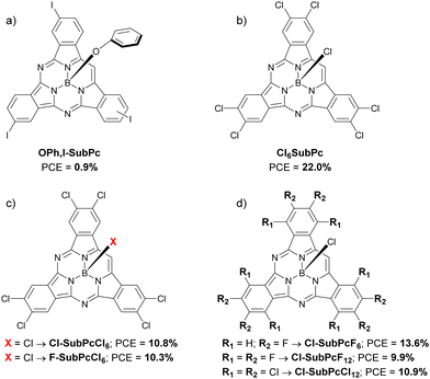 |
| | Fig. 26 Chemical structures of SubPcs (a) OPh,I-SubPc, (b) Cl6SubPc, (c) F-SubPcCl6 and Cl-SubPcF6, and (d) Cl-SubPcF6, Cl-SubPcF12 and Cl-SubPcCl12 applied in PSCs. | |
5. Phthalocyanines versus porphyrins
5.1. Hole transporting materials
Pcs have been more extensively studied as HTM in PSCs than Pors, so it is not surprising that the maximum PCE obtained each year of the period under study are higher in the case of the former (Fig. 27). It is striking that the most successful Pc structure in 2019 (OMe-TPA-CuPc, PCE = 19.67%) is an analogue of the current champion Pc-based HTM (SMe-TPA-CuPc, PCE = 23.00%). Something to keep in mind is that the Pcs with the best PCEs are usually those with a central Cu atom, except for NiPc in 2021 (PCE = 21.23%). Another structural peculiarity is the presence of heteroatoms (O, S and N) in the substituents, which allow stronger interactions with the perovskite layer and passivation of defects through interactions with the bare ions of the crystal structure. In this respect, the arylamines give very good results, perhaps because of their tendency to arrange themselves in a more favorable way. In the case of the Pors, the scarcity of trials makes it more difficult to establish a trend or a structural pattern. What is observed is that, like the Pcs, the presence of heteroatoms in the substituents gives rise to the type of interactions necessary for improved performance of the PSCs. The great PCE of 22.67% obtained for the Por MDA4 in 2022 makes us think that these porphyrinoids could easily rival Pcs in terms of efficiency but still far in stability.
 |
| | Fig. 27 Evolution from 2019 to 2022 of maxima PCEs of PSCs with Pcs (green lines and molecules) and Pors (pink lines and molecules) as HTMs. | |
5.2. Additives
Undoubtedly, Pors and Pcs as additives in the perovskite layer led to improved performance of PSCs (Fig. 28). In this application, the Pors stand out against the Pcs, whose maxima PCEs in 2021 and 2022 were greater than 24% with the molecules NiP and CuP-S2, almost 3% better than that of the best Pc (HCuPc, PCE = 21.39%). In fact, Pors-based additives have been improving since 2019, when the maximum PCE obtained was 20.46%, to the maximum value reached in 2021 and 2022 (>24%), which seems to have stagnated. Thus, both Ni and Cu offered better performance than Zn in the case of Pors. The PSCs added with Pcs have also been improving to date, going from PCE = 10.79% (SiPc) in 2019 to PCE = 21.39% in 2022, although they are still far from their Pors analogs. Unlike the Pors, the molecular structures of the best Pcs are quite varied; from an axially substituted SiPc, through a CuPc without substituents and ending in a star-shaped oligomer CuPc, which is also the one that has given rise to the best performance among Pcs in this application.
 |
| | Fig. 28 Evolution from 2019 to 2022 of maxima PCEs of PSCs with Pcs (green lines and molecules) and Pors (pink lines and molecules) as additives. | |
5.3. Interlayers
Until 2021, the best results as interlayers had been obtained with Pors, but quite recently in 2022 the Pcs surpassed them (Fig. 29), although the best PCE was set in 2021 for the Por CS1 (22.37%), and its value has not yet been exceeded so far. From a structural point of view, CS1 is an asymmetric molecule of the donor–π–acceptor type. As in the cases of HTMs and additives, the presence of heteroatoms in porphyrinoid substituents is related to stronger interactions with the perovskite crystal layer, leading to passivation of defects.
 |
| | Fig. 29 Evolution from 2019 to 2022 of maxima PCEs of PSCs with Pcs (green lines and molecules) and Pors (pink lines and molecules) as interlayers. | |
6. Conclusions and future outlook
The most relevant works on Pcs, Pors and other porphyrinoids as components of PSCs from the last four years have been reviewed. With only a few exceptions, all the molecules presented here showed to provide better performance for PSCs than spiro-OMeTAD, especially in terms of stability. However, there are still plenty of work to be done in structural modification of phorphyrinoids to increase PSC performance and here we will propose some. From the structural point of view, it seems that, in general, the central Cu atoms improve photovoltaic performance in all vacuum and in solution processed devices. No CuPc dimers have been prepared so far and they could be quite interesting systems to increase the PSC performance and stability. The incorporation of other metals yielding highly conductive macrocycles, as for example radical lanthanoid bisphthalocyanines,139 LiPc,140 PbPc,141 could be a promising route to explore. The presence of more O, S or N heteroatoms in the long alkyl chains would favor the LUMO levels and improve the conductivity, as they would act by passivating defects through interactions with partially naked ions in the crystal lattice of the perovskite layer. Their incorporation also will increase the stability taking into consideration that hydrophobicity seems to be a critical parameter. The donor–acceptor–donor approach in Pcs, which allows the modulation of energy levels, especially the HOMO, is still unexplored. In the case of Pcs, the arylamino-substituted compounds stand out, especially the ethynyl derivative with more than 23% PCE. The study of this substitution pattern in CuPors could be interesting. Higher extension of the conjugation, synthesis of 2D and 3D systems, and looking for NIR photoresponse phorphyrinoids are unexplored strategies that could be adequate to suppress defects due to a better crystallization of the active layer as well as a reduction of the trap-state density through the interaction with the I− anions. On the other hand, where Pors stand out is as additives in the active layer, providing PCEs beyond 24% and good stabilities. As they are added in a small proportion, it is an option to consider in the fabrication of PSCs. While Pcs as additives also stand out for the stability they provide, although they still lag behind Pors in terms of efficiency. There is no doubt that the synthesis of push–pull ABCB substituted Pcs would have all the adequate characteristics to be explored as HTM and as additives. However, these unsymmetrically substituted Pcs, due to the synthetic difficulty, remain as an exciting challenge that the best synthetic phthalocyanine groups should pursue. Regarding other porphyrinoids, tetrabenzotriazacorroles showed promise as dopant-free HTMs. Regarding subphthalocyanines, there are few studies, mainly as ETM, and the obtained results are disparate, so we consider that there is still a long way to go, and it is worth going further.
Thus, Pcs and Pors have proved to be strong candidates for perovskite-based solar panels coming to market soon, not only because they can rival other materials in terms of efficiency at lower cost, but also because they provide better stabilities than most other materials.
Conflicts of interest
There are no conflicts to declare.
Acknowledgements
ASS wants to thank the European Regional Development Fund “A way to make Europe” and the Spanish Ministerio de Ciencia e Innovación/Agencia Estatal de Investigación (PID2020-117855 RB-I00), the Generalitat Valenciana (CIPROM/2021/059) and the Advanced Materials program by MCIN with funding from European Union NextGenerationEU (PRTR-C17.I1) and Generalitat Valenciana (MFA/2022/028) for funding.
References
- A. Kojima, K. Teshima, Y. Shirai and T. Miyasaka, J. Am. Chem. Soc., 2009, 131, 6050 CrossRef CAS PubMed.
-
https://www.nrel.gov/pv/assets/pdfs/best-research-cell-efficiencies-rev220126.pdf
.
- H. Min, D. Y. Lee, J. Kim, G. Kim, K. S. Lee, J. Kim, M. J. Paik, Y. K. Kim, K. S. Kim, M. G. Kim, T. J. Shin and S. I. Seok, Nature, 2021, 598, 444 CrossRef CAS PubMed.
- S. De Wolf, J. Holovsky, S.-J. Moon, P. Löper, B. Niesen, M. Ledinsky, F.-J. Haug, J.-H. Yum and C. Ballif, J. Phys. Chem. Lett., 2014, 5, 1035 CrossRef CAS PubMed.
- S. D. Stranks, G. E. Eperon, G. Grancini, C. Menelaou, M. J. P. Alcocer, T. Leijtens, L. M. Herz, A. Petrozza and H. J. Snaith, Science, 2013, 342, 341 CrossRef CAS PubMed.
- L. M. Herz, ACS Energy Lett., 2017, 2, 1539 CrossRef CAS.
- G. E. Eperon, S. D. Stranks, C. Menelaou, M. B. Johnston, L. M. Herz and H. J. Snaith, Energy Environ. Sci., 2014, 7, 982 RSC.
- N. L. Chang, A. W. Y. Ho-Baillie, D. Vak, M. Gao, M. A. Green and R. J. Egan, Sol. Energy Mater. Sol. Cells, 2018, 174, 314 CrossRef CAS.
- M. Karimipour, S. Khazraei, B. J. Kim, G. Boschloo and E. M. J. Johansson, Nano Energy, 2022, 95, 107044 CrossRef CAS.
- A. Kotta, I. Seo, H.-S. Shin and H.-K. Seo, Chem. Eng. J., 2022, 435, 134805 CrossRef CAS.
- Z. Ahmad, A. S. Shikoh, S. Paek, M. K. Nazeeruddin, S. A. Al-Muhtaseb, F. Touati, J. Bhadra and N. J. Al-Thani, J. Mater. Sci.: Mater. Electron., 2019, 30, 1354 CrossRef CAS.
- N. Aristidou, C. Eames, M. S. Islam and S. A. Haque, J. Mater. Chem. A, 2017, 5, 25469 RSC.
- F. M. Rombach, S. A. Haque and T. J. Macdonald, Energy Environ. Sci., 2021, 14, 5161 RSC.
- F. Liu, Z. Xing, Y. Ren, R.-J. Huang, P.-Y. Xu, F.-F. Xie, S.-H. Li and X. Zhong, Nanomaterials, 2022, 12, 1046 CrossRef CAS PubMed.
- Z. Yu, A. Hagfeldt and L. Sun, Coord. Chem. Rev., 2020, 406, 213143 CrossRef CAS.
- L. Jia, M. Chen and S. Yang, Mater. Chem. Front., 2020, 4, 2256 RSC.
- S. Sajid, H. Huang, J. Ji, H. Jiang, M. Duan, X. Liu, B. Liu and M. Li, Renewable Sustainable Energy Rev., 2021, 152, 111689 CrossRef CAS.
- D. Klyamer, R. Shutilov and T. Basova, Sensors, 2022, 22, 895 CrossRef CAS PubMed.
-
(a) W. Borzęcka, A. Domiński and M. Kowalczuk, Nanomaterials, 2021, 11, 2426 CrossRef PubMed;
(b) L. Žárská, Z. Malá, K. Langová, L. Malina, S. Binder, R. Bajgar and H. Kolářová, Photodiagn. Photodyn. Ther., 2021, 34, 102224 CrossRef PubMed.
-
(a) M. T. Nazeri, S. Javanbakht, M. Nabi and A. Shaabani, Carbohydr. Polym., 2022, 283, 119144 CrossRef CAS PubMed;
(b) T. Takanami and K. Suda, J. Synth. Org. Chem. Jpn., 2009, 67, 595 CrossRef CAS.
- M. Urbani, M.-E. Ragoussi, M. K. Nazeeruddin and T. Torres, Coord. Chem. Rev., 2019, 381, 1 CrossRef CAS.
- M. D. M. Faure, C. Dindault, N. A. Rice and B. H. Lessard, ACS Omega, 2022, 7, 7541 CrossRef CAS PubMed.
- S. S. Rawat, A. Rana, A. Kumar, S. K. Swami, R. Srivastava and C. K. Suman, Sol. Energy, 2022, 231, 623 CrossRef CAS.
- Y. Matsuo, K. Ogumi, I. Jeon, H. Wang and T. Nakagawa, RSC Adv., 2020, 10, 32678 RSC.
- H. Ye, Z. Liu, X. Liu, B. Sun, X. Tan, Y. Tu, T. Shi, Z. Tang and G. Liao, Appl. Surf. Sci., 2019, 478, 417 CrossRef CAS.
- M. Kam, Y. Zhu, D. Zhang, L. Gu, J. Chen and Z. Fan, Sol. RRL, 2019, 3, 1900050 CrossRef.
- Y. Feng, Q. Chen, L. Dong, Z. Zhang, C. Li, S. Yang, S. Cai and Z.-X. Xu, Sol. Energy, 2019, 184, 649 CrossRef CAS.
- Q. Hu, E. Rezaee, L. Dong, Q. Dong, H. Shan, Q. Chen, M. Li, S. Cai, L. Wang and Z.-X. Xu, Sol. RRL, 2019, 3, 1900182 CrossRef CAS.
- G. Zanotti, N. Angelini, G. Mattioli, A. M. Paoletti, G. Pennesi, D. Caschera, A. P. Sobolev, L. Beverina, A. M. Calascibetta, A. Sanzone, A. Di Carlo, B. B. Berna, S. Pescetelli and A. Agresti, ChemPlusChem, 2020, 85, 2376 CrossRef CAS PubMed.
- S.-W. Kim, G. Kim, C. S. Moon, T.-Y. Yang and J. Seo, Small Methods, 2021, 5, 2001248 CrossRef CAS PubMed.
- C. Li, Q. Hu, Q. Chen, W. Yu, J. Xu and Z.-X. Xu, Org. Electron., 2021, 88, 106018 CrossRef CAS.
- P. Huang, A. Hernández, S. Kazim, J. Follana-Berná, J. Ortiz, L. Lezama, Á. Sastre-Santos and S. Ahmad, ACS Appl. Energy Mater., 2021, 4, 10124 CrossRef CAS.
- J. Peng, J. I. Khan, W. Liu, E. Ugur, T. Duong, Y. Wu, H. Shen, K. Wang, H. Dang, E. Aydin, X. Yang, Y. Wan, K. J. Weber, K. R. Catchpole, F. Laquai, S. De Wolf and T. P. White, Adv. Energy Mater., 2018, 8, 1801208 CrossRef.
- H. Kim, K. S. Lee, M. J. Paik, D. Y. Lee, S.-U. Lee, E. Choi, J. S. Yun and S. I. Seok, Adv. Funct. Mater., 2022, 32, 2110473 CrossRef CAS.
- Q. Hu, E. Rezaee, Q. Dong, H. Shan, Q. Chen, L. Wang, B. Liu, J.-H. Pan and Z.-X. Xu, Sol. RRL, 2019, 3, 1800264 CrossRef.
- F. Qi, B. Wu, J. Xu, Q. Chen, H. Shan, J. Xu and Z.-X. Xu, Chin. Phys. B, 2021, 30, 108801 CrossRef CAS.
- D. Molina, M. A. Ruiz-Preciado, F. Sadegh, M. J. Álvaro-Martins, M. Grätzel, A. Hagfeldt and Á. Sastre-Santos, J. Porphyrins Phthalocyanines, 2019, 23, 546 CrossRef CAS.
- D. Molina, M. A. Ruiz-Preciado, B. Carlsen, F. T. Eickemeyer, B. Yang, N. Flores-Díaz, M. J. Álvaro-Martins, K. Nonomura, A. Hagfeldt and Á. Sastre-Santos, ChemPhotoChem, 2020, 4, 307 CrossRef CAS.
- M. Pegu, D. Molina, M. J. Álvaro-Martins, M. Castillo, L. Ferrer, S. Kazima, Á. Sastre-Santos and S. Ahmad, J. Mater. Chem. C, 2022, 10, 11975 RSC.
- J. G. Manion, M. Yuan, F. P. García de Arquer, G. R. McKeown, S. Beaupré, M. Leclerc, E. H. Sargent and D. S. Seferos, Adv. Mater., 2016, 28, 6491 CrossRef PubMed.
- J.-M. Wang, Z.-K. Wang, M. Li, C.-C. Zhang, L.-L. Jiang, K.-H. Hu, Q.-Q. Ye and L.-S. Liao, Adv. Energy Mater., 2018, 8, 1701688 CrossRef.
- C. V. Kumar, G. Sfyri, D. Raptis, E. Stathatos and P. Lianos, RSC Adv., 2015, 5, 3786 RSC.
- T. Duong, J. Peng, D. Walter, J. Xiang, H. Shen, D. Chugh, M. Lockrey, D. Zhong, J. Li, K. Weber, T. P. White and K. R. Catchpole, ACS Energy Lett., 2018, 3, 2441 CrossRef CAS.
- Y. Feng, Q. Hu, E. Rezaee, M. Li, Z.-X. Xu, A. Lorenzoni, F. Mercuri and M. Muccini, Adv. Energy Mater., 2019, 9, 1901019 CrossRef.
- K. T. Cho, M. Cavazzini, K. Rakstys, S. Orlandi, S. Paek, M. Franckevičius, H. Kanda, R. Gegevičius, Q. V. Emmanuel, G. Pozzi and M. K. Nazeeruddin, ACS Appl. Energy Mater., 2019, 2, 6195 CrossRef CAS.
- Z. Cui, Y. Wang, Y. Chen, X. Chen, X. Deng, W. Chen and C. Shi, Org. Electron., 2019, 69, 248 CrossRef CAS.
- P. Huang, A. Hernández, S. Kazim, J. Ortíz, Á. Sastre-Santos and S. Ahmad, Sustainable Energy Fuels, 2020, 4, 6188 RSC.
- N. Klipfel, J. Xia, P. Culík, S. Orlandi, M. Cavazzini, N. Shibayama, H. Kanda, C. Igci, W. Li, Y.-B. Cheng, V. Jankauskas, K. Genevicius, A. M. Asiri, C. Momblona, K. Rakstys, G. Pozzi and M. K. Nazeeruddin, Mater. Today Energy, 2022, 29, 101110 CrossRef CAS.
- G. Qu, L. Dong, Y. Qiao, D. Khan, Q. Chen, P. Xie, X. Yu, X. Liu, Y. Wang, J. Chen, X. Chen and Z.-X. Xu, Adv. Funct. Mater., 2022, 2206585 CrossRef CAS.
- J. Guo, X. Meng, H. Zhu, M. Suna, Y. Wanga, W. Wang, M. Xing and F. Zhang, Org. Electron., 2019, 64, 71 CrossRef CAS.
- X. Jiang, D. Wang, Z. Yu, W. Ma, H.-B. Li, X. Yang, F. Liu, A. Hagfeldt and L. Sun, Adv. Energy Mater., 2019, 9, 1803287 CrossRef.
- Q. Hu, E. Rezaee, M. Li, Q. Chen, Y. Cao, M. Mayukh, D. V. McGrath and Z.-X. Xu, ACS Appl. Mater. Interfaces, 2019, 11, 36535 CrossRef CAS PubMed.
- X. Ding, C. Chen, L. Tao, C. Wu, M. Zheng, H. Lu, H. Xu, H. Li and M. Cheng, Chem. Eng. J., 2020, 387, 124130 CrossRef CAS.
- C. Li, R. He, Q. Liang, J. Cao, J. Yin and Y. Tang, Sci. China: Chem., 2020, 63, 1053 CrossRef CAS.
- Z. Yu, L. Wang, X. Mu, C.-C. Chen, Y. Wu, J. Cao and Y. Tang, Angew. Chem., Int. Ed., 2021, 60, 6294 CrossRef CAS PubMed.
- W. Chen, H. Zhang, J. Sun, R. Ghadari, Z. Zhang, F. Pan, K. Lv, X. Sun, F. Guo and C. Shi, J. Power Sources, 2021, 505, 230095 CrossRef CAS.
- M. Haider, C. Zhen, T. Wu, J. Wu, C. Jia, G. Liu and H.-M. Cheng, Chem. Commun., 2019, 55, 5343 RSC.
- M. M. Tavakoli, P. Yadav, D. Prochowicz and R. Tavakoli, Sol. RRL, 2021, 5, 2000552 CrossRef CAS.
- S. Seto, Jpn. J. Appl. Phys., 2021, 60, SBBF10 CrossRef CAS.
- X. Zhao, W. Zhang, X. Feng, X. Guo, C. Lu, X. Li and J. Fang, Chem. Eng. J., 2022, 435, 135140 CrossRef CAS.
- E. Aktas, J. Jiménez-López, K. Azizi, T. Torres and E. Palomares, Nanoscale Horiz., 2020, 5, 1415 RSC.
- Z. Dalkılıç, C. B. Lee, H. Choi, I. Nar, N. K. Yavuz and A. K. Burat, J. Organomet. Chem., 2020, 922, 121419 CrossRef.
- D. Han, S. Yi, Q. Yuan, X. Tang, Q. Shu, Q. Li, F. Wang, D.-Y. Zhou and L. Feng, Small, 2021, 17, 2101902 CrossRef CAS PubMed.
- S. H. Lee, S. Hong, H. H. Lee and H. J. Kim, Adv. Mater. Interfaces, 2021, 8, 2001891 CrossRef CAS.
- A. Suzuki, H. Okumura, Y. Yamasaki and T. Oku, Appl. Surf. Sci., 2019, 488, 586 CrossRef CAS.
- M.-F. Xu, Y.-L. Jin, T. Xu, C.-N. Wang and Z.-C. Zhai, Org. Electron., 2021, 89, 106025 CrossRef CAS.
- R. Li, J. Ding, X. Muc, Y. Kang, A. Wanga, W. Bi, Y. Zhang, J. Cao and Q. Dong, J. Energy Chem., 2022, 71, 141 CrossRef CAS.
- K.-W. Lai, C. Hanmandlu, C. C. Chang and C.-W. Chu, Org. Electron., 2022, 108, 106568 CrossRef CAS.
- S. Zhang, Z. Hu, J. Zhang, X. Jia, J. Jiang, Y. Chen, B. Lin, H. Jiang, B. Fang, N. Yuan and J. Ding, J. Power Sources, 2019, 438, 226987 CrossRef CAS.
- H. Lai, X. Li, S. Li, Y. Chen, B. Sun, Q. Jiang and J. Yang, Electrochim. Acta, 2019, 296, 799 CrossRef CAS.
- C. Xie, C. Zhou, B. Yang, L. Shen, L. Ke, L. Ding and Y. Yuan, Appl. Phys. Express, 2019, 12, 064006 CrossRef CAS.
- Q. Hu, E. Rezaee, W. Xu, R. Ramachandran, Q. Chen, H. Xu, T. EL-Assaad, D. V. McGrath and Z.-X. Xu, Small, 2021, 17, 2005216 CrossRef CAS PubMed.
- G. Qu, D. Khan, F. Yan, A. Atsay, H. Xiao, Q. Chen, H. Xub, I. Nar and Z.-X. Xu, J. Energy Chem., 2022, 67, 263 CrossRef CAS.
- Z. Zhang, H. Liu, S. Wang, H. Bao, F. Zhang and X. Li, Adv. Funct. Mater., 2022, 2208539 CrossRef CAS.
- A. Kumar, S. K. Ojha, N. Vyas and A. K. Ojha, ACS Omega, 2021, 6, 7086 CrossRef CAS PubMed.
- S. He, L. Qiu, D.-Y. Son, Z. Liu, E. J. Juarez-Perez, L. K. Ono, C. Stecker and Y. Qi, ACS Energy Lett., 2019, 4, 2032 CrossRef CAS.
- A. Mahmood, J.-Y. Hu, B. Xiao, A. Tang, X. Wang and E. Zhou, J. Mater. Chem. A, 2018, 6, 16769 RSC.
- S. Ramasamy, M. Bhagavathiachari, S. A. Suthanthiraraj and M. Pichai, Dyes Pigm., 2022, 203, 110380 CrossRef CAS.
- K. Zeng, Z. Tong, L. Ma, W.-H. Zhu, W. Wu and Y. Xie, Energy Environ. Sci., 2020, 13, 1617 RSC.
- V. Piradi, F. Yan, X. Zhu and W.-Y. Wong, Mater. Chem. Front., 2021, 5, 7119 RSC.
- S. Mathew, A. Yella, P. Gao, R. Humphry-Baker, B. F. E. Curchod, N. Ashari-Astani, I. Tavernelli, U. Rothlisberger, M. K. Nazeeruddin and M. Grätzel, Nat. Chem., 2014, 6, 242 CrossRef CAS PubMed.
- D. Sygkridou, A. Apostolopoulou, A. Charisiadis, V. Nikolaou, G. Charalambidis, A. G. Coutsolelos and E. Stathatos, ChemistrySelect, 2018, 3, 2536 CrossRef CAS.
- S. Chen, P. Liu, Y. Hua, Y. Li, L. Kloo, X. Wang, B. Ong, W. K. Wong and X. Zhu, ACS Appl. Mater. Interfaces, 2017, 9, 13231 CrossRef CAS PubMed.
- M. N. Shah, S. R. Pathipati and N. Ahmed, J. Mater. Sci.-Mater. Electron., 2019, 30, 7866 CrossRef CAS.
- W. Zhang, Y. Hua, L. Wang, B. Zhang, Y. Li, P. Liu, V. Leandri, Y. Guo, H. Chen, J. M. Gardner, L. Sun and L. Kloo, ACS Appl. Energy Mater., 2019, 2, 6768 CrossRef CAS.
- C.-L. Mai, Q. Xiong, X. Li, J.-Y. Chen, J.-Y. Chen, C.-C. Chen, J. Xu, C. Liu, C.-Y. Yeh and P. Gao, Angew. Chem., Int. Ed., 2022, 61, e202209365 CrossRef CAS PubMed.
- H.-H. Chou, Y.-H. Chiang, Y.-H. Chen, C.-J. Guo, H.-Y. Zuo, W.-T. Cheng, P.-Y. Lin, Y.-Y. Chiu, P. Chen and C.-Y. Yeh, Sol. RRL, 2020, 4, 2000119 CrossRef CAS.
- J.-X. Zhang, Y. Wu, J.-C. Liu and R.-Z. Li, Dalton Trans., 2016, 45, 16283 RSC.
- Y. Wu, Q. Zhang and J.-C. Liu, Org. Electron., 2017, 41, 301 CrossRef CAS.
- X. Lv, G. Xiao, X. Feng, J. Cao, X. Yao and J. Liu, Dyes Pigm., 2019, 160, 957 CrossRef CAS.
- M. Freitag, Q. Daniel, M. Pazoki, K. Sveinbjörnsson, J. B. Zhang, L. C. Sun, A. Hagfeldt and G. Boschloo, Energy Environ. Sci., 2015, 8, 2634 RSC.
- Y. M. Cao, Y. Saygili, A. Ummadisingu, J. Teuscher, J. S. Luo, N. Pellet, F. Giordano, S. M. Zakeeruddin, J.-E. Moser, M. Freitag, A. Hagfeldt and M. Grätzel, Nat. Commun., 2017, 8, 15390 CrossRef PubMed.
- C.-D. Si, X.-D. Lv and S.-J. Long, Inorg. Chem. Commun., 2020, 112, 107701 CrossRef CAS.
- T. Leijtens, E. G. Eperon, N. K. Noel, S. N. Habisreutinger, A. Petrozza and H. J. Snaith, Adv. Energy Mater., 2015, 5, 1500963 CrossRef.
- X. Zheng, B. Chen, J. Dai, Y. Fang, Y. Bai, Y. Lin, H. Wei, X. C. Zeng and J. Huang, Nat. Energy, 2017, 2, 17102 CrossRef CAS.
- J. Xu, A. Buin, A. H. Ip, W. Li, O. Voznyy, R. Comin, M. Yuan, S. Jeon, Z. Ning, J. J. McDowell, P. Kanjanaboos, J.-P. Sun, X. Lan, L. N. Quan, D. H. Kim, I. G. Hill, P. Maksymovych and E. H. Sargent, Nat. Commun., 2015, 6, 7081 CrossRef CAS PubMed.
- C. M. M. Soe, W. Nie, C. C. Stoumpos, H. Tsai, J.-C. Blancon, F. Liu, J. Even, T. J. Marks, A. D. Mohite and M. G. Kanatzidis, Adv. Energy Mater., 2018, 8, 1700979 CrossRef.
- J. Lu, X. Lin, X. Jiao, T. Gengenbach, A. D. Scully, L. Jiang, B. Tan, J. Sun, B. Li, N. Pai, U. Bach, A. N. Simonov and Y.-B. Cheng, Energy Environ. Sci., 2018, 11, 1880 RSC.
- T. Niu, J. Lu, R. Munir, J. Li, D. Barrit, X. Zhang, H. Hu, Z. Yang, A. Amassian, K. Zhao and S. F. Liu, Adv. Mater., 2018, 30, 1706576 CrossRef PubMed.
- L. Jiang, J. Zheng, W. Chen, Y. Huang, L. Hu, T. Hayat, A. Alsaedi, C. Zhang and S. Dai, ACS Appl. Energy Mater., 2017, 1, 93 CrossRef.
- X. Feng, R. Chen, Z.-A. Nan, X. Lv, R. Meng, J. Cao and Y. Tang, Adv. Sci., 2019, 6, 1802040 CrossRef PubMed.
- C. Li, J. Yin, R. Chen, X. Lv, X. Feng, Y. Wu and J. Cao, J. Am. Chem. Soc., 2019, 141, 6345 CrossRef CAS PubMed.
- X. Li, C. Li, Y. Wu, J. Cao and Y. Tang, Sci. China: Chem., 2020, 63, 777 CrossRef CAS.
- Z. Fang, L. Wang, X. Mu, B. Chen, Q. Xiong, W. D. Wang, J. Ding, P. Gao, Y. Wu and J. Cao, J. Am. Chem. Soc., 2021, 143, 18989 CrossRef CAS PubMed.
- J.-H. Zhao, X. Mu, L. Wang, Z. Fang, X. Zou and J. Cao, Angew. Chem., Int. Ed., 2022, 61, e202116308 CAS.
- X. Li, C.-C. Chen, M. Cai, X. Hua, F. Xie, X. Liu, J. Hua, Y.-T. Long, H. Tian and L. Han, Adv. Energy Mater., 2018, 8, 1800715 CrossRef.
- L. Zuo, H. Guo, D. W. de Quilettes, S. Jariwala, N. De Marco, S. Dong, R. DeBlock, D. S. Ginger, B. Dunn, M. Wang and Y. Yang, Sci. Adv., 2017, 3, e1700106 CrossRef PubMed.
- Y. Zhou, H. Zhong, J. Han, M. Tai, X. Yin, M. Zhang, Z. Wu and H. Lin, J. Mater. Chem. A, 2019, 7, 26334 RSC.
- K. Su, W. Chen, Y. Huang, G. Yang, K. G. Brooks, B. Zhang, Y. Feng, M. K. Nazeeruddin and Y. Zhang, Sol. RRL, 2022, 6, 2100964 CrossRef CAS.
- X.-L. Zheng, H.-S. Lin, B.-W. Zhang, S. Maruyama and Y. Matsuo, J. Org. Chem., 2022, 87, 5457 CrossRef CAS PubMed.
- Y. Liang, P. Song, H. Tian, C. Tian, W. Tian, Z. Nan, Y. Cai, P. Yang, C. Sun, J. Chen, L. Xie, Q. Zhang and Z. Wei, Adv. Funct. Mater., 2022, 32, 2110139 CrossRef CAS.
- R. Guo, L. Rao, Q. Liu, H. Wang, C. Gong, B. Fan, Z. Xing, X. Meng and X. Hu, J. Energy Chem., 2022, 66, 612 CrossRef CAS.
- J. Liang, Z. Liu, L. Qiu, Z. Hawash, L. Meng, Z. Wu, Y. Jiang, L. K. Ono and Y. Qi, Adv. Energy
Mater., 2018, 8, 1800504 CrossRef.
- W. Liu, L. Chu, N. Liu, Y. Ma, R. Hu, Y. Weng, H. Li, J. Zhang, X. A. Li and W. Huang, J. Mater. Chem. C, 2019, 7, 11943 RSC.
- K. Gkini, N. Balis, M. Papadakis, A. Verykios, M.-C. Skoulikidou, C. Drivas, S. Kennou, M. Golomb, A. Walsh, A. G. Coutsolelos, M. Vasilopoulou and P. Falaras, ACS Appl. Energy Mater., 2020, 3, 7353 CrossRef CAS.
- L. Hu, W. Wang, H. Liu, J. Peng, H. Cao, G. Shao, Z. Xia, W. Ma and J. Tang, J. Mater. Chem. A, 2015, 3, 515 RSC.
- M. Que, Z. Dai, H. Yang, H. Zhu, Y. Zong, W. Que, N. P. Padture, Y. Zhou and O. Chen, ACS Energy Lett., 2019, 4, 1970 CrossRef CAS.
- X. Zheng, J. Troughton, N. Gasparini, Y. Lin, M. Wei, Y. Hou, J. Liu, K. Song, Z. Chen, C. Yang, B. Turedi, A. Y. Alsalloum, J. Pan, J. Chen, A. A. Zhumekenov, T. D. Anthopoulos, Y. Han, D. Baran, O. F. Mohammed, E. H. Sargent and O. M. Bakr, Joule, 2019, 3, 1963 CrossRef CAS.
- J. Li, L. Xu, T. Wang, J. Song, J. Chen, J. Xue, Y. Dong, B. Cai, Q. Shan, B. Han and H. Zeng, Adv. Mater., 2017, 29, 1603885 CrossRef PubMed.
- X.-X. Feng, X.-D. Lv, Q. Liang, J. Cao and Y. Tang, ACS Appl. Mater. Interfaces, 2020, 12, 16236 CrossRef CAS PubMed.
- G.-B. Xiao, Z.-F. Yu, J. Cao and Y. Tang, CCS Chem., 2020, 2, 488 CrossRef CAS.
- P. Yan, J. Cao, J. Pang, Z. Yang, X. Wang and X. Yao, Org. Electron., 2021, 93, 106158 CrossRef CAS.
- G.-B. Xiao, L.-Y. Wang, X.-J. Mu, X.-X. Zou, Y.-Y. Wu and J. Cao, CCS Chem., 2021, 3, 25 CrossRef CAS.
- C. Li, L. Wang, P.-J. Yan, H. Liu, J. Cao, C.-C. Chen and Y. Tang, Chem. Eng. J., 2021, 409, 128167 CrossRef CAS.
- K. Gkini, A. Verykios, N. Balis, A. Kaltzoglou, M. Papadakis, K. S. Adamis, K.-K. Armadorou, A. Soultati, C. Drivas, S. Gardelis, I. D. Petsalakis, L. C. Palilis, A. Fakharuddin, M. I. Haider, X. Bao, S. Kennou, P. Argitis, L. Schmidt-Mende, A. G. Coutsolelos, P. Falaras and M. Vasilopoulou, ACS Appl. Mater. Interfaces, 2020, 12, 1120 CrossRef CAS PubMed.
- C.-L. Mai, Q. Zhou, Q. Xiong, C.-C. Chen, J. Xu, Z. Zhang, H.-W. Lee, C.-Y. Yeh and P. Gao, Adv. Funct.
Mater., 2021, 31, 2007762 CrossRef CAS.
- K. Su, P. Zhao, Y. Ren, Y. Zhang, G. Yang, Y. Huang, Y. Feng and B. Zhang, ACS Appl. Mater. Interfaces, 2021, 13, 14248 CrossRef CAS PubMed.
- X. Feng, Y. Huan, C. Zheng, C. Tan, H. Meng, B. Liu, D. Gao and W. Huang, Org. Electron., 2020, 77, 105522 CrossRef CAS.
- H. Liang, W. D. Wang, S. Mai, X. Lv, J. Fang and J. Cao, Chem. Eng. J., 2022, 429, 132405 CrossRef CAS.
- X.-F. Zhang, Coord. Chem. Rev., 2015, 285, 52 CrossRef CAS.
- X.-F. Zhang, C. Liu, J. Wu and B. Xu, J. Energy Chem., 2020, 43, 139 CrossRef.
- X. Lu and X.-F. Zhang, Dyes Pigm., 2020, 179, 108421 CrossRef CAS.
- G. Sfyri, C. V. Kumar, G. Sabapathi, L. Giribabu, K. S. Andrikopoulos, E. Stathatos and P. Lianos, RSC Adv., 2015, 5, 69813 RSC.
- E. J. Juarez-Perez, M. Wuβler, F. Fabregat-Santiago, K. Lakus-Wollny, E. Mankel, T. Mayer, W. Jaegermann and I. Mora-Sero, J. Phys. Chem. Lett., 2014, 5, 680 CrossRef CAS PubMed.
- R. García-Aboal, H. García, S. Remiro-Buenamañana and P. Atienzar, Dalton Trans., 2021, 50, 6100 RSC.
- W. Chen, B. Han, Q. Hu, M. Gu, Y. Zhu, W. Yang, Y. Zhou, D. Luo, F.-Z. Liu, R. Cheng, R. Zhu, S.-P. Feng, A. B. Djurišić, T. P. Russell and Z. He, Sci. Bull., 2021, 66, 991 CrossRef CAS PubMed.
- J. Labella, C. Momblona, N. Klipfel, H. Kanda, S. Kinge, M. K. Nazeeruddin and T. Torres, J. Mater. Chem. C, 2021, 9, 16298 RSC.
- J. Labella, C. Momblona, P. Čulík, E. López-Serrano, H. Kanda, M. K. Nazeeruddin and T. Torres, Front. Chem., 2022, 10, 886522 CrossRef CAS PubMed.
- C. Pal, I. Chambrier, A. N. Cammidge, A. K. Sharma and A. K. Ray, J. Porphyrins Phthalocyanines, 2019, 23, 1603–1615 CrossRef CAS.
- M. Dumm, P. Lunkenheimer, A. Loidl, B. Assmann and H. Homborg, J. Chem. Phys., 1996, 104, 5048–5053 CrossRef CAS.
- S. Ambily and C. S. Menon, Mater. Lett., 1998, 36, 61–64 CrossRef CAS.
|
| This journal is © The Royal Society of Chemistry 2023 |
Click here to see how this site uses Cookies. View our privacy policy here. 
 ,
Jorge
Follana-Berná
,
Jorge
Follana-Berná