 Open Access Article
Energy, exergy, economic, and environmental (4E) analysis of a pumped thermal energy storage system for trigeneration in buildings
Panagiotis
Lykas
a,
Evangelos
Bellos
 *ab,
Dimitrios N.
Korres
a,
Angeliki
Kitsopoulou
a and
Christos
Tzivanidis
a
aDepartment of Thermal Engineering, School of Mechanical Engineering, National Technical University of Athens, Athens, Greece. E-mail: bellose@central.ntua.gr
bDepartment of Mechanical Engineering Educators, School of Pedagogical and Technological Education (ASPETE), Attika, Irakleio, 14121, Greece
First published on 10th February 2023
Abstract
The decarbonization of the building sector is a crucial aspect for meeting various and increasing human demands in a more environmentally friendly and sustainable way. The purpose of the present work is to analyze a configuration that combines the concept of pumped thermal energy storage with a trigeneration approach. The studied unit, which is appropriate for the building sector, is fed with excess electricity from photovoltaic panels, and it stores energy in the form of heat and produces electricity, heating, and cooling when it is needed to meet all the basic building demands. The whole configuration consists of a multi-stage heat pump with two evaporators and two condensers. Three latent storage devices based on phase change materials that provide heating and cooling, as well as an organic Rankine cycle unit for power generation, are also integrated. The overall system was examined through thermodynamic equations parametrically under steady-state conditions and tested with different eco-friendly working fluids. Furthermore, the proposed unit was evaluated in terms of finance and carbon emission avoidance. With a cooling load of 50 kW, heating load of 50 kW, and high-temperature thermal load of 50 kW and taking toluene as the working fluid, cooling storage temperature of 5 °C, heating storage temperature of 60 °C, and high-thermal storage temperature of 125 °C, energy and exergy efficiencies were determined to be 322.9% and 49.7% respectively. Finally, if the system operates for 2000 h per year, and the payback period and net present value were found to be 2.67, and 324 k€ respectively, while the total annual equivalent carbon emission avoidance was calculated to be 45.6 tCO2-eq per year.
1. Introduction
Over the past few decades, the global energy demand has rapidly increased due to overpopulation, industrial development, and rising living standards. The combustion of conventional fossil fuels is widely used to meet human needs, resulting in increased greenhouse gas and pollutant emission as well as serious environmental problems.1 As the key solution to this problem, the concept of decarbonization has been proposed, which is based on low-carbon, environmentally friendly, and sustainable energy processes.2 Buildings are responsible for 31% of global final energy demand and 23% of global carbon emissions.3 To achieve the decarbonization of the building sector, the integration of renewable energy sources, the electrification of heating and cooling processes, as well as the installation of storage devices are crucial parameters.4Energy production from renewable sources varies due to fluctuations in weather conditions during the day and the year. Therefore, the generation does not always keep pace with the energy demand. To increase the stability and reliability of renewable energy plants, it is important to develop efficient and sustainable energy storage systems.5 One of the most promising storage technologies is the pumped thermal energy storage (PTES) concept. A PTES system consists of a heat pump, which stores the electricity input from renewables as thermal energy, and a power cycle, which converts it again into electricity output. A vapor compression or a Brayton cycle is used as a heat pump, while a Brayton or an organic Rankine cycle (ORC) is selected as a power cycle. Thermal energy can be stored as sensible heat, as latent heat using phase change materials (PCM) or via chemical reaction mechanisms.6
In the literature, numerous configurations based on PTES technology are reported. First of all, Albert et al.7 investigated the performance of a PTES system numerically, which included Argon-based Brayton cycles for charge and discharge processes. Both PCM and packed-bed storage units were integrated, while the whole installation achieved round-trip efficiencies of up to 80%. Moreover, Eppinger et al.8 studied a configuration consisting of a vapor-compression cycle as a heat pump and an ORC. Both sensible and latent storage units, as well as a handful of working fluids, were examined for various operating conditions. Therefore, values of power-to-power efficiency over 80% were calculated. Roskosch and Atakan9 analyzed a similar configuration that was called a pumped heat electricity storage system and was made up of a heat pump, a thermal storage unit, and an ORC. Considering irreversible cycles, values of roundtrip efficiency up to 70% were found. Furthermore, Okten and Kursun10 analyzed a PTES unit that was made up of a heat pump and an ORC. The integration of an absorption refrigeration cycle was investigated to decrease the ORC condenser evaporating pressures. This decrease could lead to higher ORC power production. According to the results, the ORC electricity production increased by 15.3% to 41.5% for the case of using the absorption refrigeration cycle, while the round-trip efficiency and the levelized cost of storage also increased and were found to be 142%, and 0.242 $ per kW per h. Finally, Tillmanns et al.11 studied a PTES configuration thermo-economically, which included a heat pump and an ORC. To optimize the system in terms of its properties and working media, the authors developed the 1-stage Continuous-Molecular Targeting – Computer-Aided Molecular Design method. For the optimum case, the specific investment cost was determined to be 929 € kW hel,out, considering an input electrical load of 60 MW.
Apart from these, some researchers have investigated PTES installations that were assisted by an additional renewable energy source, such as geothermal energy, solar irradiation, or biomass. First, Wang et al.12 investigated two cases of PTES systems thermodynamically and thermo-economically. The first one included an ORC as its discharge cycle, while the second one included an organic flash cycle. In both cases, a heat pump that was fed with geothermal energy was incorporated as the charge cycle. The ORC-based configuration performed better energetically, and financially, the power-to-power efficiency and levelized cost of storage were found to be 68.42% and 0.34 $ per kW per h, respectively, while for the case of using the organic flash cycle, the aforementioned values were calculated to be 33.55% and 0.83 $ per kW per h, respectively. Moreover, Frate et al.13 examined a thermally integrated PTES unit that was made up of a compound parabolic collector field, a high-temperature heat pump, which was fed with heat produced by the collectors, as well as an ORC. Therefore, the round trip efficiency was calculated, which ranged from 0.85 to 0.87. Bellos et al.14 studied a PTES configuration, which included a heat pump, a latent storage device, and an ORC. The heat pump was fueled with low-temperature heat that was produced by a flat plate collector's field, while its compressors were powered by electricity. The stored heat was exploited by the ORC for power generation when needed. According to the results, the electricity recovery ratio, ORC efficiency, and coefficient of performance of the heat pump were determined to be 68.5%, 18.5%, and 3.7, respectively. In addition, Kong et al.15 analyzed a configuration that was based on a heat pump coupled with an ORC and could produce heating, as an additional output, apart from electricity. The rejected heat from the heat pump was provided as heat input to the ORC and was exploited to generate useful heat, too. A biomass boiler was also incorporated as an auxiliary heat source for the ORC. The heat pump also generated chilled water, which was provided to the ORC condenser to reduce the condensing temperature and improve cycle performance. Therefore, with a condensing temperature of 30 °C, instead of 40 °C, the overall performance has been improved. The ORC energy and exergy efficiencies were calculated to be 11.92% and 60.45%, respectively, while the overall system energy and exergy efficiencies were found to be 50.5% and 12.21%, respectively.
Most of the aforementioned studies focused on electricity storage into thermal energy and the conversion again into electricity. Nevertheless, there is a lack of research studies on storage configurations that can provide more than one useful output, such as heating or cooling, in the building sector. The present work combines the PTES technology with the trigeneration approach for filling this gap. The examined configuration consists of a multi-stage heat pump that is fed with excess electricity produced by renewable energy-based systems such as photovoltaics and coupled with three latent storage units based on PCMs. Therefore, the surplus electricity is exploited by storing it in the form of heat at three different temperature levels. More specifically, the low-temperature cooling storage system produces cooling, while the medium-temperature heating storage system can provide useful heat for space heating, and domestic hot water. Additionally, the high-temperature heating storage unit can be used for heat input into an ORC for electricity production, when solar irradiation is not available and the photovoltaics are out of order, for example, on cloudy days or at night. Therefore, the proposed configuration was fed with electricity produced from renewable energy sources, and provided various useful outputs to meet the building demands. The whole system was studied parametrically and evaluated for different working fluids, while the analysis was carried out using the Engineering Equation Solver (EES) software.16 Finally, the economic viability and impact of the configuration on global warming were investigated.
2. Material and methods
2.1. System outline
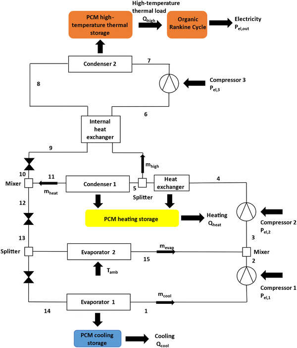
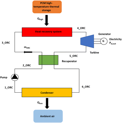
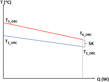
The investigated installation contains a PTES unit that is associated with latent storage devices and an ORC, and it can generate electricity, heating, and cooling. More specifically, as shown in Fig. 1, a multi-stage heat pump is integrated and its compressors are fed with electricity from the grid or renewable sources. It consists of two evaporators, the first one is fed with the ambient source and the second one is coupled with a cooling storage system that covers the cooling demands. Furthermore, the heat pump rejects heat into two different temperature heat sinks. The medium-temperature storage system is responsible for space heating and domestic hot water, while the high-temperature storage unit can be used for heat input into an ORC for electricity production. Therefore, there are 4 different pressure levels in the whole system: the two evaporating pressure levels (Pevap,1) and (Pevap,2), and the two condensing pressure levels (Pcond,1) and (Pcond,2). Considering the aforementioned saturation pressure values, four corresponding saturation temperature levels can be assumed, which are (Tevap,1), (Tevap,2), (Tcond,1), and (Tcond,2). The following assumptions are made for them: (Tevap,1) is 5 K lower than the cooling storage temperature (Tcool), (Tevap,2) is 5 K lower than the ambient temperature (Tamb), (Tcond,1) is 5 K greater than the heating storage temperature (Theat), and (Tcond,2) is 5 K greater than the high-thermal storage temperature (Thigh). Practically, the pinch points were selected to be 5 K, which are reasonable values for achieving a possible operation with reduced exergy destruction losses.14The fluid after leaving compressor 2 enters the heat exchanger where it reaches saturated steam conditions at point (5), while the rejected heat is utilized in the medium-temperature storage device. Subsequently, the flow is split and the working medium enters an internal heat exchanger, and is superheated by the fluid leaving condenser 2, to avoid the existence of liquid droplets in the inlet of compressor 3 and achieve higher performance. In the internal heat exchanger, a temperature difference at the hot side of this heat exchanger is assumed to be 5 K. All the storage devices are based on PCMs as a more compact approach, which possibly store energy for a couple of weeks. In addition, the ambient source evaporator 2 is used to counterweight the loads. During the cold winter months, evaporator 1 and low-stage compressor 1 can be out of order. Furthermore, zero superheating and subcooling are assumed for evaporators and condensers, respectively, to make the modeling more simple. In practice, in most of the cases, a low degree of subcooling or superheating is applied. In parallel, a regenerative ORC is utilized to improve the efficiency, as illustrated in Fig. 2, with a temperature difference at the cold side of the recuperator that is equal to 5 K.14 A temperature–heat content (T–Q) diagram is depicted in Fig. 3. Finally, for the ORC unit, it is also assumed that the condenser saturation temperature is 10 K greater than the ambient temperature to reject heat, while both the evaporator pinch point (PP) and superheating rate (ΔTsh) are considered to be equal to 5 K.14
2.2. Mathematical modeling
The first part of the mathematical formulation is devoted to heat pump modeling. The cooling production (Qcool) is equal to the load of evaporator 1, considering that no energy gains or losses occur, and it is described as follows:| Qcool = mcool·(h1 − h14) | (1) |
The heat input from the ambient source (Qamb), which is equal to the load of evaporator 2, is described as follows:
| Qamb = mevap·(h15 − h13) | (2) |
The medium-temperature heating production (Qheat), which is the sum of condenser 1 and the heat exchanger load, considering that no energy gains or losses occur, is described as follows:
| Qheat = (mcool + mevap)·(h4 − h5) + mheat·(h5 − h11) | (3) |
The high-temperature thermal load (Qhigh) is described as follows:
| Qhigh = mhigh·(h7 − h8) | (4) |
The electricity consumption of compressor 1 is described as follows:
 | (5) |
The isentropic efficiency of compressor 1 is described as follows:
 | (6) |
The electricity consumption of compressor 2 is described as follows:
 | (7) |
The isentropic efficiency of compressor 2 is described as follows:
 | (8) |
The electricity consumption of compressor 3 is described as follows:
 | (9) |
The isentropic efficiency of compressor 3 is described as follows:
 | (10) |
The total electricity input (Pel,in) to the system consists of the electricity consumption of the 3 compressors and is described using the following equation:
| Pe1,in = Pe1,1 + Pe1,2 + Pe1,3 | (11) |
In addition, the ORC is described using the following equations. First of all, the heat input in the ORC (QORC), which is the same as the high-temperature thermal load (Qhigh) because no energy gains or losses occur, can also be described as follows:
| QORC = mORC (h4_ORC−h3_ORC) | (12) |
In the ORC evaporator, the saturation temperature (Tsat) of the organic fluid is considered as follows:
| Tsat = Thigh − ΔTsh − PP | (13) |
The electricity output of the ORC (Pel,out) is expressed as the produced electricity from the generator minus the electricity consumption of the feeding pump using the following equation:
 | (14) |
The isentropic efficiency for the ORC pump can be written as follows:
 | (15) |
The isentropic efficiency for ORC turbine can be written as follows:
 | (16) |
Thus, the thermodynamic efficiency of the ORC (ηORC) is determined as follows:
 | (17) |
To sum up, the overall energy balance of the heat pump is expressed by the following equation:
| Qhigh + Qheat = Qcool + Qamb + Pel,in | (18) |
Consequently, the system can be evaluated by its overall energy and exergy efficiencies. The system energy efficiency (ηen) is determined as follows:
 | (19) |
The system exergy efficiency (ηex) is calculated as follows:
 | (20) |
The input constant parameters of the thermodynamic model are presented in Table 1.
| Heat pump constant parameters | Values |
|---|---|
| Isentropic efficiency of compressors (ηis,1, ηis,2, ηis,3) | 85% |
| Compressor electro-mechanical efficiency (ηmg) | 97% |
| Temperature difference of evaporators | 5 K |
| Temperature difference of condensers | 5 K |
| Internal heat exchanger temperature difference | 5 K |
| ORC constant parameters | |
| Turbine isentropic efficiency (ηis,turb) | 85% |
| Pump isentropic efficiency (ηis,pump) | 80% |
| Pump motor efficiency (ηmotor) | 80% |
| Turbine electro-mechanical efficiency (ηmg) | 97% |
| Evaporator pinch point (PP) | 5 K |
| Superheating (ΔTsh) | 5 K |
| Recuperator temperature difference | 5 K |
| Condenser temperature difference | 10 K |
2.3. Financial analysis
First of all, it is essential to define the investment cost of the unit (Ctotal), which is the total of the cost of the ORC system, heat pump, and PCMs. Regarding the PCM cost, a specific cost that is equal to 2 € per kg is considered.17 It is assumed that the PCM stores heat for 4 hours, taking into account a typical value of latent heat that is equal to 200 kJ kg−1.18 Thus, the overall capital cost is described using the following equation:| Ctotal = CORC + CHP + CPCM | (21) |
Furthermore, to calculate the annual cash flow (CF), both annual inflows and outflows have to be determined. The annual inflows include the financial savings due to electricity, heating, and cooling generation. However, the annual outflows regard the operation and maintenance costs. At this point, it is important to mention that the cost of the electricity input to the system is not taken into account, as the electricity input comes from surplus renewable electricity (photovoltaics). Thus, the expression is defined as follows:
| CF = Yel,out·Kel + Yheat·Kheat + Ycool·Kcool − KO&M | (22) |
(Yel,out), (Yheat), and (Ycool) are the yearly electricity, heating, and cooling production expressed in kW h respectively, while (Kel), (Kheat), and (Kcool) are the cost of electricity, heating, and cooling expressed in € per kW per h, respectively. Through the capital cost and the annual cash flow, the main financial indexes can be calculated, which are the simple payback period (SPBP), payback period (PBP), net present value (NPV), and internal rate of return (IRR). The corresponding equations are given below and all the financial parameters are presented in Table 2.
 | (23) |
 | (24) |
 | (25) |
 | (26) |
| Financial parameters | Values |
|---|---|
| Cost of electricity (Kel) | 0.25 € per kW per h |
| Cost of heating (Kheat) | 0.15 € per kW per h |
| Cost of cooling (Kcool) | 0.07 € per kW per h |
| ORC specific cost | 1800 € per kWel |
| Heat pump's specific cost | 300 € per kWcool |
| Project lifetime (N) | 25 years |
| Discount factor (i) | 4% |
| Operation & maintenance cost (KO&M) | 2% of the capital cost |
2.4. Carbon emission avoidance
The examined installation is fed with excess electricity from photovoltaic panels, which cannot be absorbed by the grid, and produces three useful products, i.e., electricity through an ORC module when the photovoltaics are out of order, heating, and cooling. Therefore, it is assumed that the system is not responsible for carbon emissions during its operation. On the contrary, it is considered that the unit prevents carbon emissions in comparison with other conventional energy technologies. The total annual equivalent carbon emission (CEannual) avoidance in tCO2-eq per year can be defined using the following equation:| CEannual = CEel·Yel,out + CEheat·Yheat + CEcool·Ycool | (27) |
(CEel) is the equivalent carbon emissions of electricity generation for the Greek electricity mix, and is considered to be 0.604 kgCO2-eq kW−1 hel−1.21 Additionally, (CEheat) is the equivalent carbon emissions of heat production. It is assumed that the heating load is conventionally covered by a natural gas boiler, with an efficiency of 85%, and hence, the aforementioned value was determined to be 0.212 kgCO2-eq kW−1 hth−1.22 Finally, (CEcool) is the equivalent carbon emissions of cooling production, which are defined taking into account an R32 air-conditioner driven by electricity with a coefficient of performance (COP) that is equal to 4.23
2.5. Simulation methodology
First of all, the present installation was investigated thermodynamically under steady-state conditions using a software program written in the EES, which is based on the previously mentioned model and equations. For all the calculations that were carried out, a cooling load of 50 kW, a heating load of 50 kW, a high-temperature thermal load of 50 kW, and an ambient temperature of 25 °C were considered. The whole system was studied parametrically, while the main examined parameters were cooling, heating, and high-thermal storage temperature values, which varied in a specific range. The cooling storage temperature ranges from 0 to 10 °C, with a default value of 5 °C, the heating storage temperature ranges from 50 to 60 °C, with a default value of 55 °C, and the high-thermal storage temperature ranges from 100 to 150 °C, with a default value of 125 °C. Moreover, the plant performance was investigated for different working fluids, which have low global warming potential (GWP) and zero ozone depletion potential (ODP). The working medium is considered to be utilized for both the heat pump and ORC. The examined working fluids are R1233zd(E), toluene, cyclopentane, n-pentane, and n-heptane.24,25 The properties of these fluids are presented in Table 3.| Working fluid | P crit (bar) | T crit (°C) | ODP | GWP |
|---|---|---|---|---|
| R1233zd(E) | 36.2 | 166.5 | 0 | 4.5 |
| Toluene | 41.2 | 318.5 | 0 | ∼3.3 |
| Cyclopentane | 45.7 | 238.5 | 0 | ∼3 |
| n-Pentane | 33.7 | 196.5 | 0 | <3 |
| n-Heptane | 27.4 | 267.1 | 0 | ∼20 |
Subsequently, the design case that leads to the maximum exergy efficiency was selected to be examined economically defining the main financial indexes for different operating hours during the year. Finally, the equivalent tonnes of CO2 emissions that are avoided per year are calculated assuming that the electricity, heating, and cooling demands, that the proposed system covers, are met via conventional technologies.
3. Results and discussion
3.1. Thermodynamic analysis
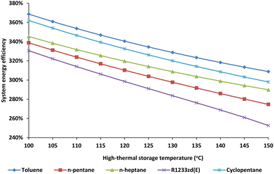
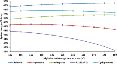
After the basic thermodynamic calculations, the most important outputs are the overall system energy and exergy efficiency. These results are presented in the following diagrams depending on the main parameters, which are cooling, heating, and high-thermal storage temperature values. The illustrated results include the configuration performance for all the examined working fluids.At first, overall energy and exergy efficiencies depending on the high-thermal storage temperature are shown in Fig. 4 and 5. As it is illustrated in Fig. 4, the energy efficiency decreases significantly with the increase in high-thermal storage temperature for all the examined working fluids. In Fig. 5, it is important to state that for the case of using cyclopentane and n-pentane, the exergy efficiency is slightly varied depending on the high-thermal storage temperature and reaches a maximum value, while for the case of utilizing the R1233zd(E), the exergy efficiency has a significant decreasing rate. In contrast, if n-heptane or toluene is utilized as a working medium, the exergy efficiency has an increasing rate. The highest values of both energy and exergy efficiencies are found in the case of using toluene.
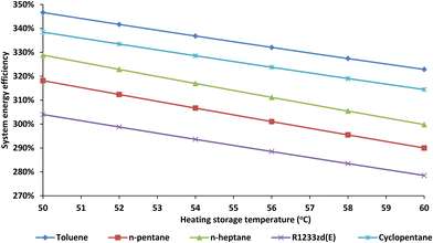
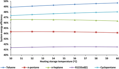
In addition, the overall energy and exergy efficiencies depending on the heating storage temperature are shown in Fig. 6 and 7. As it is shown in Fig. 6, the energy efficiency decreases with the increase in high-thermal storage temperature for all the examined working fluids. In Fig. 7, it is important to state that for the cases of utilizing R1233zd(E), n-pentane, and n-heptane, the exergy efficiency is slightly varied depending on the heating storage temperature, while for the case of using cyclopentane and toluene, the exergy efficiency has an increasing rate. The highest values of both energy and exergy efficiencies are found for the case utilizing toluene.
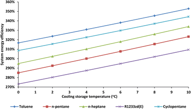
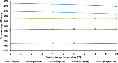
Moreover, the overall energy and exergy efficiencies depending on the cooling storage temperature are shown in Fig. 8 and 9. As it is presented in Fig. 8, the energy efficiency increases with the increase in cooling storage temperature for all the examined working fluids. In Fig. 9, it is important to state that for the cases of using R1233zd(E), n-pentane, and n-heptane, the exergy efficiency is slightly varied depending on the cooling storage temperature, while for the case of using cyclopentane and toluene, the exergy efficiency has a decreasing rate. The highest values of both energy and exergy efficiencies are found for the case of utilizing toluene.
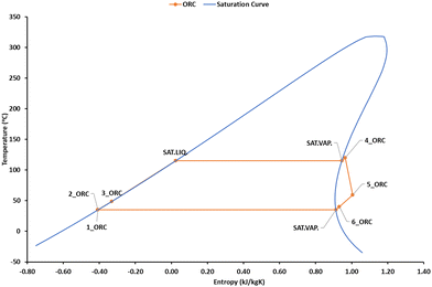
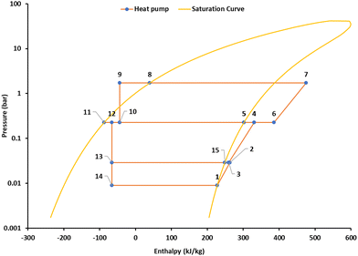
Consequently, taking toluene as a working medium, at a cooling storage temperature of 5 °C, a heating storage temperature of 55 °C, and a high-thermal storage temperature of 100 °C, the configuration achieved its highest value of energy efficiency that is equal to 368.7% and the corresponding exergy efficiency was determined to be 48.7%. Furthermore, for the case of using a cooling storage temperature of 5 °C, a heating storage temperature of 60 °C, and a high-thermal storage temperature of 125 °C, the maximum exergy efficiency was calculated to be equal to 49.7%, while the respective energy efficiency was found to be 322.9%. The main parameters and outputs for the case of maximum exergy efficiency are presented in Table 4. For the same case, the temperature–specific entropy (T–s) diagram of the ORC and the pressure–specific enthalpy (P–h) diagram of the heat pump are depicted in Fig. 10 and 11, respectively.
| Parameters | Values |
|---|---|
| Cooling storage temperature (Tcool) | 5 °C |
| Heating storage temperature (Theat) | 60 °C |
| High-thermal storage temperature (Thigh) | 125 °C |
| Cooling storage load (load of evaporator 1) (Qcool) | 50 kW |
| Heating storage load (Qheat) | 50 kW |
| High-temperature storage load (load of condenser 2) (Qhigh) | 50 kW |
| Load of evaporator 2 (Qamb) | 17.63 kW |
| Load of condenser 1 (Qcond1) | 43.6 kW |
| Total mass flow (m) | 0.227 kg s−1 |
| Evaporator 1 mass flow (mcool) | 0.171 kg s−1 |
| Evaporator 2 mass flow (mevap) | 0.056 kg s−1 |
| Condenser 1 mass flow (mheat) | 0.111 kg s−1 |
| Condenser 2 mass flow (mhigh) | 0.115 kg s−1 |
| Electric power of compressor 1 (Pel,1) | 6.3 kW |
| Electric power of compressor 2 (Pel,2) | 16.6 kW |
| Electric power of compressor 3 (Pel,3) | 10.5 kW |
| Input electric power (Pel,in) | 33.4 kW |
| Output electric power (Pel,out) | 7.7 kW |
| System energy efficiency (ηen) | 322.9% |
| System exergy efficiency (ηex) | 49.7% |
| ORC energy efficiency (ηorc) | 15.5% |
3.2. Financial and emission avoidance analysis
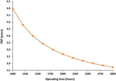
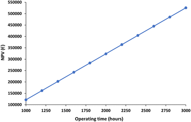
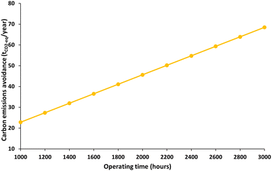
In this section, the main financial indexes, as well as the carbon emission avoidance considering different values of operating hours per year, are presented. These values were calculated for the design case that achieved the maximum exergy efficiency. In this operation scenario, toluene was used as a working medium, while the cooling storage temperature, the heating storage temperature, and the high-thermal storage temperature were 5 °C, 60 °C, and 125 °C, respectively. The payback period for different operating hours is shown in Fig. 12. More specifically, the payback period is determined to be 6 years for 1000 operating hours per year, which then decreases exponentially, and reaches the value of 1.7, when the system operates for 3000 hours per year. Moreover, the net present value for different operating hours is depicted in Fig. 13. According to the results, the net present value has a linearly increasing rate with the increase in the operating hours. The net present value is equal to 122 k€ if the system operates for 1000 hours per year, while it is found to be 526 k€ when the annual operating hours are equal to 3000. Moreover, carbon emission avoidance is illustrated in Fig. 14. The avoided equivalent CO2 emissions are equal to 22.8 tCO2-eq per year if the system operates for 1000 hours per year. This value increases linearly and reaches the value of 68.5 tCO2-eq per year when the operating hours are equal to 3000 annually. Finally, considering an average value of 2000 operating hours per year, the financial and emission avoidance results are presented in Table 5.| Outputs | Values |
|---|---|
| Simple payback period (SPBP) | 2.48 |
| Payback period (PBP) | 2.67 |
| Net present value (NPV) | 324 k€ |
| Internal rate of return (IRR) | 40.3% |
| Annual equivalent carbon emissions avoidance (CEannual) | 45.6 tCO2-eq per year |
4. Conclusions
The purpose of this research paper is to present and investigate a pumped thermal storage system associated with the concept of trigeneration thermodynamically. The unit exploits surplus electricity supplied by photovoltaic panels to produce cooling and useful heat for space heating and domestic hot water via the corresponding storage devices, as well as electricity by an ORC powered by high-temperature thermal storage when solar irradiation is not available. The main conclusions of the analysis are the following:• The most appropriate working medium is toluene both energetically and exegetically, which has a low impact on global warming.
• The energy efficiency decreases with the increase in high-thermal and heating storage temperatures, while it has an increasing rate depending on the cooling temperature.
• The exergy efficiency is slightly varied depending on the cooling, heating, and high-thermal storage temperatures.
• The most influential parameter is the high-thermal storage temperature.
• The maximum achieved energy and exergy efficiencies are 368.7% and 49.7%, respectively.
• Assuming 2000 operating hours per year, the simple payback period is equal to 2.48, the payback period is found to be 2.67, and while the net present value is determined to be 324 k€.
• The total annual equivalent carbon emission avoidance is found to be 45.6 tCO2-eq per year.
Nomenclature
| C | Component cost, € |
| CE | Equivalent carbon emissions, kgCO2-eq kW−1 h−1 or tCO2-eq per year |
| CF | Cash flow, € |
| C total | Capital cost, € |
| h | Specific enthalpy, kJ kg−1 |
| i | Interest rate |
| IRR | Internal rate of return, % |
| K | Product cost, € |
| m | Mass flow rate, kg s−1 |
| N | Project lifetime, years |
| NPV | Net present value, € |
| P | Pressure, bar |
| PBP | Payback period, years |
| P el | Electric power, kW |
| P el,in | Input electric power, kW |
| P el,out | Output electric power, kW |
| PP | Pinch point, K |
| Q | Heat rate, kW |
| s | Specific entropy, kJ kg−1 K−1 |
| SPBP | Simple payback period, years |
| T | Temperature, °C |
| Y | Yearly parameter, kW h−1 |
Greek symbols
| ΔT | Temperature difference, K |
| η | Efficiency, % |
Subscripts
| amb | Ambient |
| annual | Annual |
| CO2 | Carbon dioxide |
| cond | Condenser |
| cool | Cooling |
| crit | Critical point |
| el | Electrical |
| en | Energy |
| eq | Equivalent |
| evap | Evaporator |
| ex | Exergy |
| heat | Heating storage |
| high | High-thermal storage |
| HP | Heat pump |
| in | Inlet |
| is | Isentropic |
| mg | Electro-mechanical |
| motor | Motor |
| O&M | Operation and maintenance |
| ORC | Organic Rankine cycle |
| out | Outlet |
| PCM | Phase change material |
| pump | Pump |
| sat | Saturation |
| sh | Superheating |
| th | Thermal |
| turb | Turbine |
Abbreviations
| COP | Coefficient of performance |
| EES | Engineering Equation Solver |
| GWP | Global warming potential |
| ODP | Ozone depletion potential |
| ORC | Organic Rankine cycle |
| PCM | Phase change material |
| PTES | Pumped thermal energy storage |
Conflicts of interest
There are no conflicts to declare.References
- Y. Yang, Y. Huang, P. Jiang and Y. Zhu, Multi-objective optimization of combined cooling, heating, and power systems with supercritical CO2 recompression Brayton cycle, Appl. Energy, 2020, 271, 115189 CrossRef CAS.
- R. M. Elavarasan, R. Pugazhendhi, M. Irfan, L. Mihet-Popa, I. A. Khan and P. E. Campana, State-of-the-art sustainable approaches for deeper decarbonization in Europe – An endowment to climate neutral vision, Renewable Sustainable Energy Rev., 2022, 159, 112204 CrossRef.
- M. Schwarz, C. Nakhle and C. Knoeri, Innovative designs of building energy codes for building decarbonization and their implementation challenges, J. Cleaner Prod., 2020, 248, 119260 CrossRef.
- B. Tarroja, F. Chiang, A. AghaKouchak, S. Samuelsen, S. V. Raghavan, M. Wei, K. Sun and T. Hong, Translating climate change and heating system electrification impacts on building energy use to future greenhouse gas emissions and electric grid capacity requirements in California, Appl. Energy, 2018, 225, 522–534 CrossRef.
- I. Sarbu, C. Sebarchievici and A. Comprehensive, Review of Thermal Energy Storage, Sustainability, 2018, 10, 191 CrossRef.
- O. Dumont, G. F. Frate, A. Pillai, S. Lecompte, M. Depaepe and V. Lemort, Carnot battery technology: A state-of-the-art review, J. Energy Storage, 2020, 32, 101756 CrossRef.
- M. Albert, Z. Ma, H. Bao and A. P. Roskilly, Operation and performance of Brayton Pumped Thermal Energy Storage with additional latent storage, Appl. Energy, 2022, 312, 118700 CrossRef.
- B. Eppinger, L. Zigan, J. Karl and S. Will, Pumped thermal energy storage with heat pump-ORC-systems: Comparison of latent and sensible thermal storages for various fluids, Appl. Energy, 2020, 280, 115940 CrossRef CAS.
- D. Roskosch and B. Atakan, Pumped heat electricity storage: Potential analysis and ORC requirements, Energy Procedia, 2017, 129, 1026–1033 CrossRef.
- K. Okten and B. Kursun, Thermo-economic assessment of a thermally integrated pumped thermal energy storage (TI-PTES) system combined with an absorption refrigeration cycle driven by low-grade heat source, J. Energy Storage, 2022, 51, 104486 CrossRef.
- D. Tillmanns, D. Pell, J. Schilling and A. Bardow, The Thermo-Economic Potential of ORC-Based Pumped-Thermal Electricity Storage: Insights from the Integrated Design of Processes and Working Fluids, Energy Technol., 2022, 10, 2200182 CrossRef CAS.
- P. Wang, Q. Li, C. Liu, R. Wang, Z. Luo, P. Zou and S. Wang, Comparative analysis of system performance of thermally integrated pumped thermal energy storage systems based on organic flash cycle and organic Rankine cycle, Energy Convers. Manage., 2022, 273, 116416 CrossRef CAS.
- G. F. Frate, A. Baccioli, L. Bernardini and L. Ferrari, Assessment of the off-design performance of a solar thermally-integrated pumped-thermal energy storage, Renewable Energy, 2022, 201, 636–650 CrossRef.
- E. Bellos, C. Tzivanidis and Z. Said, Investigation and optimization of a solar-assisted pumped thermal energy storage system with flat plate collectors, Energy Convers. Manage., 2021, 237, 114137 CrossRef.
- R. Kong, T. Deethayat, A. Asanakham and T. Kiatsiriroat, Performance analysis of biomass boiler-organic Rankine cycle with assisted cascade heat pump for combined heat and power generation including exergy-costing, Sustainable Energy Technol. Assess., 2022, 52, 102125 CrossRef.
- F-Chart Software, Engineering Equation Solver (EES), 2015, available online: https://www.fchart.com/ees, accessed on 1 September 2022.
- A. Bland, M. Khzouz, T. Statheros and E. I. Gkanas, PCMs for Residential Building Applications: A Short Review Focused on Disadvantages and Proposals for Future Development, Buildings, 2017, 7, 78, DOI:10.3390/buildings7030078.
- M. J. Mochane, T. C. Mokhena, T. E. Motaung and L. Z. Linganiso, Shape-stabilized phase change materials of polyolefin/wax blends and their composites, A systematic review, J. Therm. Anal. Calorim., 2020, 139, 2951–2963 CrossRef CAS.
- E. Bellos, L. Vellios, I.-C. Theodosiou and C. Tzivanidis, Investigation of a solar-biomass polygeneration system, Energy Convers. Manage., 2018, 173, 283–295 CrossRef.
- P. Lykas, E. Bellos, G. Caralis and C. Tzivanidis, Dynamic Investigation and Optimization of a Solar-Based Unit for Power and Green Hydrogen Production: A Case Study of the Greek Island, Kythnos, Appl. Sci., 2022, 12, 11134, DOI:10.3390/app122111134.
- https://www.eea.europa.eu/ims/greenhouse-gas-emission-intensity-of-1 (accessed on: 11/8/2022).
- https://www.eia.gov/environment/emissions/co2_vol_mass.php (accessed on: 11/8/2022).
- A. Mota-Babiloni, J. Navarro-Esbrí, P. Makhnatch and F. Molés, Refrigerant R32 as lower GWP working fluid in residential air conditioning systems in Europe and the USA, Renewable Sustainable Energy Rev., 2017, 80, 1031–1042 CrossRef CAS.
- W. K. A. Abbas and J. Vrabec, Cascaded dual-loop organic Rankine cycle with alkanes and low global warming potential refrigerants as working fluids, Energy Convers. Manage., 2021, 249, 114843 CrossRef CAS.
- L. Pierobon, T. Nguyen, A. Mazzucco, U. Larsen and F. Haglind, Part-Load Performance of a Wet Indirectly Fired Gas Turbine Integrated with an Organic Rankine Cycle Turbogenerator, Energies, 2014, 7, 8294–8316 CrossRef.
| This journal is © The Royal Society of Chemistry 2023 |

