 Open Access Article
Creative Commons Attribution 3.0 Unported Licence
From bone to nacre – development of biomimetic materials for bone implants: a review
Parinaz
Tabrizian
 a,
Sean
Davis
b and
Bo
Su
*a
aBiomaterials Engineering Group (bioMEG), Bristol Dental School, University of Bristol, UK. E-mail: b.su@bristol.ac.uk
bSchool of Chemistry, University of Bristol, UK
First published on 9th September 2024
Abstract
The field of bone repair and regeneration has undergone significant advancements, yet challenges persist in achieving optimal bone implants or scaffolds, particularly load-bearing bone implants. This review explores the current landscape of bone implants, emphasizing the complexity of bone anatomy and the emerging paradigm of biomimicry inspired by natural structures. Nature, as a master architect, offers insights into the design of biomaterials that can closely emulate the mechanical properties and hierarchical organization of bone. By drawing parallels with nacre, the mollusk shells renowned for their exceptional strength and toughness, researchers have endeavored to develop bone implants with enhanced biocompatibility and mechanical robustness. This paper surveys the literature on various nacre-inspired composites, particularly ceramic/polymer composites like calcium phosphate (CaP), which exhibit promising similarities to native bone tissue. By harnessing the principles of hierarchical organization and organic–inorganic interfaces observed in natural structures, researchers aim to overcome existing limitations in bone implant technology, paving the way for more durable, biocompatible, and functionally integrated solutions in orthopedic and dental applications.
1. Introduction
Bone implants are crucial in modern orthopedic surgeries, facilitating the repair and regeneration of compromised skeletal tissues. Despite notable progress in their development, achieving seamless integration with surrounding bone remains a formidable challenge. Successful bone implantation relies not only on material biocompatibility but also on the faithful replication of native bone tissue's intricate architecture and mechanical properties.1,2Effective bone implant design necessitates a profound understanding of bone anatomy and physiology. Bone, a dynamic hierarchical composite, exhibits exceptional strength, toughness, and regenerative capabilities owing to its organic collagen matrix reinforced with inorganic minerals like hydroxyapatite (HA).3,4 Emulating this complex architecture constitutes an ongoing endeavor in biomaterials research.
Commercial bone implant materials like stainless steel and titanium possess high strength but face significant stress shielding problems. The Young's modulus of these implants differs substantially from that of natural bone, potentially leading to bone weakening and eventual implant failure.5 Furthermore, patient heterogeneity and anatomical variations present unique obstacles in achieving optimal implant performance and longevity. Addressing these complex issues necessitates a multifaceted approach that integrates cutting-edge developments in material science, innovative implant design, advanced surgical techniques, and personalized medicine.6,7
To overcome these challenges, ongoing research endeavors focus on enhancing implant biocompatibility, bioactivity, and osseointegration. Surface modifications, including nanostructuring and bioactive coatings, show promise in accelerating healing and reducing inflammation. Furthermore, advanced imaging techniques, computer-aided design (CAD), and additive manufacturing enable the customization of implants tailored to individual patient needs.8–10
On the other hand, inspired by the intricate designs found in nature, researchers have increasingly looked to biological models as a source of innovation in implant design strategies. Among these models, nacre known for its brick-and-mortar structure stands out due to its remarkable mechanical properties. By emulating nacre's hierarchical organization and its organic–inorganic interfaces, scientists aim to develop bone implants that not only withstand mechanical stresses but also promote effective osseointegration.11,12
This review offers a comprehensive overview of current bone implant technologies and the challenges they face in achieving optimal clinical outcomes. It delves into the emerging paradigm of biomimicry in bone implant design, with a particular emphasis on the development of nacre-like composites. By analyzing the literature on these nacre-inspired ceramic composites, this paper highlights their potential to revolutionize the future of bone implants. By integrating biological inspiration with engineering innovation, nacre-like composites hold significant promise for enhancing patient outcomes, extending implant longevity, and advancing the field of regenerative medicine.
2. Anatomy and physiology of bone
Understanding the complex anatomy and physiology of bone is fundamental to appreciating the design, function, and performance of bone implants. Bones are dynamic organs composed of specialized connective tissue characterized by a unique combination of strength, flexibility, and regenerative capacity. This section provides an in-depth exploration of bone composition, microstructure, and mechanical properties, highlighting the remarkable complexity and resilience of this vital tissue.Bone in the human skeleton must meet a diverse set of functional demands most of which are mechanical. Bone tissue can be categorized into two types: (1) cortical or dense bone with 5–15% porosity, and (2) cancellous or spongy bone with 40–90% porosity.13–15
2.1. Composition
Bone tissue is primarily composed of an organic matrix and inorganic mineral, arranged in a hierarchical structure that confers strength, durability, and flexibility. The organic matrix, comprising approximately 30% of bone tissue by weight, consists mainly of collagen fibers.In addition to the organic matrix, bone contains minerals, predominantly HA crystals, which account for approximately 70% of bone tissue by weight. HA is a crystalline form of CaP, imparting rigidity and hardness to the bone while also contributing to its compressive strength. The interaction between collagen fibers and mineral crystals creates a composite material with exceptional mechanical properties, balancing flexibility with stiffness to withstand a wide range of mechanical loads.13,16,17
2.2. Microstructure
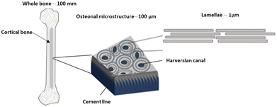
Cancellous or spongy bone, the microstructure is characterized by a network of trabeculae or bony struts arranged in a lattice-like pattern. Trabecular bone possesses a larger surface area relative to its volume compared to compact bone, making it well-suited for metabolic activities such as mineral exchange and remodeling. Additionally, trabecular bone exhibits greater porosity and flexibility, enabling it to absorb and distribute mechanical forces more effectively.18–20Cortical bone has a hierarchical microstructure in which osteons can be considered as reinforcing and toughening microelements. Osteons have a lamellae structure with 3–7 μm thickness. They are highly mineralized concentric layers composed of aligned HA/collagen fibrils. Fig. 1 shows the hierarchical structure of cortical bone from macroscale skeleton to nanoscale. This structure enables bone to be a lightweight material that can carry large loads in combination with high toughness and flexibility. Investigation at the nanoscale shows that the interaction between HA and collagen has a resounding impact on the strength and toughness of bone.14,16
2.3. Mechanical properties
Bone exhibits a remarkable combination of mechanical properties, including strength, stiffness, toughness, and elasticity, which are essential for its functions. These properties are influenced by factors such as bone density, architecture, composition, and loading conditions. The mechanical behavior of bone can be characterized by its stress–strain relationship, describing how bone deforms under applied loads. At low levels of stress, bone exhibits linear elastic behavior, where deformation is reversible, and the bone returns to its original shape once the load is removed. However, at higher stress levels, bone undergoes plastic deformation, resulting in permanent changes in shape or structure. The mechanical properties of the constituents of bone largely control its strength and plasticity. Since the material behavior of cortical bone is anisotropic, the flexural, compression strength and Young's modulus along the longitudinal direction are greater than transverse directions. Fig. 2a shows the mechanical properties and anisotropic behavior of cortical bone.11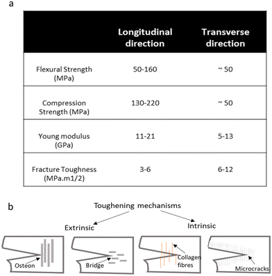 | ||
| Fig. 2 (a) The mechanical properties of cortical bone. It shows the anisotropy behavior of materials. (b) Toughening mechanisms of bone: illustration depicting the structural features and intrinsic and extrinsic mechanisms that contribute to the remarkable toughness of bone tissue.23–25 | ||
The critical stress intensity factor (KIc) and the critical strain energy release rate (Gc) are two factors for measuring the fracture toughness of cortical bones. As shown in Fig. 2a the values of KIC, are lower in longitudinal directions compared to transverse directions. The level of fracture toughness is lower at high strain rates. Cortical bone by its nature has a toughening mechanism that leads to the anisotropic value in the fracture toughness of cortical bone. As depicted in Fig. 2, toughening mechanisms correlate with the direction which can explain the anisotropy in the increase in fracture toughness with crack growth (known as a rising R-curve).
Fig. 2b illustrates the toughening mechanisms that occurred from micro to nanoscale in cortical bone. There are two types of toughening mechanisms: (1) extrinsic and (2) intrinsic, the competition between extrinsic (crack-tip shielding) and intrinsic (plastic deformation) toughening mechanisms contributes to overall toughness. Intrinsic toughening mechanisms are those that provide resistance to microstructural disruptions ahead of the crack tip, like sliding of collagen fibrils and nucleation of micro to nanoscale damages. Extrinsic toughening mechanisms by reducing the driving force of crack propagation increase the toughness, such as crack bridging and crack deflection. Osteons provide effective extrinsic toughening that is anisotropic based on the lamella directions resulting in anisotropy toughness values. The crack propagating perpendicular to the osteons (transversely oriented crack) is more likely to deflect and twist than is a crack propagating parallel to the osteon (longitudinally oriented crack).21,22
3. Current materials for bone implants and challenges
Fig. 3 shows the images of different bone implants used in orthopedic surgeries, like joint implants, spinal fusion cages, plates, nails, and screws. The key factor influencing bone healing is the movement between bone fragments, which affects tissue strain and subsequently impacts cellular responses in the fracture healing area. Therefore, the evaluation of fracture fixation methods depends on their effectiveness in minimizing such interfragmentary movement. Achieving optimal and satisfactory healing outcomes requires a deep understanding of biomechanical principles, which must be carefully considered during the application.26–29 | ||
| Fig. 3 Schematic view of various implants utilized in orthopedic surgeries. These include (a) spinal fusion, (b) plates for fracture fixation, and (c) joint implants, reproduced from ref. 27 with permission from Springer Nature, copyright 2022. | ||
In a healthy skeletal system, bones are dynamic living tissues that constantly undergo remodeling in response to mechanical stimuli. When bones experience mechanical loading, such as during weight-bearing activities, they adapt by remodeling their structure to become stronger and denser in response to increased stresses, or they may weaken in response to decreased stresses. However, when an implant is introduced, particularly one that is significantly stiffer than the surrounding bone tissue, it alters the natural stress distribution within the bone. As a result, the bone surrounding the implant experiences reduced mechanical loading, or so-called ‘stress shielding’, leading to a decrease in its natural remodeling activity. Over time, this can result in bone loss or weakening in areas not subjected to normal mechanical stresses, a phenomenon known as disuse osteoporosis. This stress shielding effect can significantly compromise bone repair and regeneration. In cases where implants are used to stabilize fractures or support damaged bone tissue, stress shielding can interfere with the natural healing process by inhibiting the bone's ability to remodel and regenerate. It can also lead to complications such as implant loosening, bone resorption, and ultimately implant failure over the long term.18,30 Therefore, in orthopedic applications, it's essential to consider the mechanical properties of both the implant and the surrounding bone tissue to minimize the detrimental effects of stress shielding. Strategies such as designing implants with mechanical properties closer to those of bone, using materials with tailored stiffness gradients, and incorporating porous features to promote bone ingrowth and integration can help mitigate stress shielding and support optimal bone repair and regeneration.
Table 1 shows the typical mechanical properties of current implant materials compared with natural bone. Although stainless steel (SS), titanium (Ti), and polyetheretherketone (PEEK) are commonly used materials for bone implants like rods, screws, plates, and spinal fusion cages. Each material has its limitations.
| Materials | Tensile strength (MPa) | Young's modulus (GPa) | Flexural strength (MPa) |
|---|---|---|---|
| Cortical bone | 50–150 | 10–25 | 80–160 |
| Titanium alloys | 900–11![[thin space (1/6-em)]](https://www.rsc.org/images/entities/char_2009.gif) 000 000 |
110–120 | 850–1200 |
| Stainless steel | 500–600 | 190–210 | 750–950 |
| Cobalt–chromium alloys | 600–1500 | 210–240 | 600–1500 |
| PEEK | 90–100 | 3.5–4.8 | 150–230 |
| PLA | 50–70 | 3.5–4 | 50–100 |
| PCL | 10–50 | 0.2–0.4 | 10–40 |
| Mg | 150–240 | 40–45 | 150–260 |
SS implants are often seen as cost-effective and easily manufactured medical devices. However, their approximately tenfold higher stiffness compared to human bone can lead to stress shielding, resulting in bone resorption. Additionally, the conductive oxides produced by SS may trigger inflammation. Despite these challenges, nickel-containing SS exhibits exceptional mechanical properties and is easily work-hardened. In its annealed condition, it demonstrates superior strength compared to other conventional SSs used in implant manufacturing, potentially enabling the development of more robust and customized implants tailored to individual patient needs.27,29
In terms of biocompatible materials, Ti and its alloys, such as commercially pure titanium (CpTi) and Ti-6Al-4 V alloy, are highly regarded despite their higher cost. These materials are prized for their excellent biocompatibility, mechanical properties, wear and corrosion resistance, high strength-to-weight ratio, and relatively lower stiffness compared to SS. Ti finds extensive use in biomedical implants, including joint replacements, bone plates, screws, pacemakers, and dental implants. Ti and its alloys generally promote satisfactory osteointegration and form a robust oxide layer, exhibiting notable resistance to corrosion. Among titanium alloys, Ti-6Al-4 V has been particularly useful.32
However, challenges exist with Ti and its alloys, such as discrepancies in composition compared to human bone, which hinder the formation of a fibrous capsule around the implant and weaken chemical bone bonding during osseointegration. Additionally, the spontaneous formation of a thin and biocompatible layer of titanium oxide enhances corrosion resistance. However, in cases of weak passivation oxide layers, the release of particles and ions from Ti implants may induce inflammation, hypersensitivity, and toxicity. The almost negligible resorption of titanium implants over time complicates diagnostic imaging, making visualization of surrounding tissues challenging.32
PEEK, a member of the polyaryletherketone (PAEK) polymer family, is known for its exceptional chemical stability, except against 98% sulfuric acid. PEEK's mechanical properties ensure long-term durability, and its versatility in three-dimensional printing and injection molding makes it ideal for intricate shapes. With Young's modulus of 3.8 GPa, lower than that of cortical bone (20.7 GPa), PEEK reduces stress shielding compared to titanium or stainless steel. The lower Young's modulus of PEEK compared to cortical bone affects implant performance. While it reduces stress shielding and helps maintain bone density, the lower stiffness can lead to insufficient mechanical support, causing micromotions at the bone–implant interface and impairing stability. Additionally, PEEK's lack of bioactivity remains a significant challenge for bone implant applications.33,34
Researchers are tackling the issue of non-bioactive commercial implant materials by exploring surface modifications, like coating with HA, and developing composite materials. These efforts aim to boost bioactivity, enhance osseointegration, and improve mechanical properties. The goal is to minimize postoperative complications and the need for further surgeries, ultimately advancing patient outcomes.35,36
Additionally, degradable polymers hold immense potential for bone implant applications due to their ability to gradually break down in the body, promoting bone regeneration while eliminating the need for subsequent removal surgeries. One such polymer is polylactic acid (PLA), which offers excellent biocompatibility, allowing it to integrate seamlessly with surrounding tissues without adverse reactions.37,38 Additionally, it possesses adequate mechanical strength to provide initial support for bone healing processes. Another degradable polymer commonly used in bone implants is polycaprolactone (PCL). PCL exhibits flexibility, durability, and ease of processing, making it suitable for various medical applications.39,40 Its gradual degradation profile allows for sustained support of bone regeneration while maintaining structural integrity over an extended period. Despite their many advantages, degradable polymers also have some limitations. One significant disadvantage is their relatively slow degradation rate, which may not always align with the pace of bone healing. In some cases, this slow degradation can lead to prolonged inflammation or mechanical instability.41 Additionally, the mechanical properties of degradable polymers may not match those of natural bone, potentially compromising the overall stability and functionality of the implant. Moreover, the processing and fabrication of degradable polymer implants can be more complex and costly compared to traditional non-degradable materials like titanium or stainless steel.
Magnesium (Mg) is emerging as a promising material for bone implant applications due to its notable biocompatibility and bioactivity, which are essential for promoting bone regeneration. When implanted, Mg interacts with surrounding tissues and fluids, facilitating the formation of an apatite layer that enhances osseointegration. One of the key advantages of magnesium is its biodegradability; unlike non-degradable materials, Mg implants gradually dissolve in the physiological environment, eliminating the need for surgical removal. This property not only reduces the risk of long-term complications associated with permanent implants but also allows for natural bone remodeling and regeneration to proceed without impediment.42,43
A significant advantage of magnesium is its mechanical properties, particularly its Young's modulus of ∼40 GPa, which is closer to that of natural bone. This similarity helps in mitigating the problem of ‘stress shielding’. However, Mg's rapid degradation rate poses a challenge, as it must be controlled to match the pace of bone healing to ensure optimal performance and stability. Additionally, the degradation process of Mg releases hydrogen gas (H2), which can cause gas pockets and local inflammation if not properly managed.44,45
4. Development of biomimetic materials for bone implants
Conventional grafts, such as autografts and allografts have long been used in bone repair and reconstruction. While these methods provide vital solutions, they come with limitations such as limited availability, risk of immune rejection, and less than optimal integration with the host tissue. For instance, autografts are highly biocompatible but require an additional surgical site for tissue harvesting, and allografts may suffer from immune responses or disease transmission.13In response to these limitations, the field has turned to biomimetic materials designed to replicate the structural and functional characteristics of natural tissues. While biomimetic materials, such as hydrogels that mimic the water-rich environment of natural tissues, have shown promise in applications like wound healing and cartilage repair, they may not be the ideal option for future bone implants.46 One significant drawback is that biomimetic materials often struggle to achieve the same level of complexity and mechanical strength as natural tissues, particularly in load-bearing applications like bone implants. Additionally, the production of biomimetic materials can be costly and complex, further limiting their potential for widespread use in bone implant technologies.47
Building on the progress of biomimetic materials, nacre-like materials represent a significant leap forward. Inspired by the natural structure of nacre (mother-of-pearl), these materials feature a layered, hierarchical design that provides exceptional toughness and mechanical strength.48 Nacre's unique structure characterized by its layered arrangement of aragonite and organic matrix serves as a model for creating synthetic materials with superior durability and resistance to fracture. For example, nacre-inspired composites and 3D-printed scaffolds utilize this hierarchical organization to enhance load-bearing capability, integration with natural bone, and overall durability. These materials are particularly advantageous in bone repair applications, offering improved mechanical performance and biocompatibility compared to traditional and biomimetic materials.49,50
4.1. Nacre-like composite materials
Efforts to replicate the mechanical properties of cortical bone in synthetic biomaterials underscore the challenge of mimicking its intricate microstructural complexity. The complexity of cortical bone's microstructure poses a significant challenge in biomimetic design. Replicating its properties accurately requires mimicking not only the composition of collagen and HA but also their spatial arrangement and interactions across multiple length scales. Conventional biomaterials often struggle to achieve such intricate hierarchical structures, limiting their ability to fully emulate cortical bone's mechanical behavior.1,51Nacre, found in the inner layer of abalone shells, possesses remarkable mechanical properties due to its sophisticated architecture, comprising highly oriented inorganic aragonite (calcium carbonate) platelets and organic biopolymer. The ‘brick’ component consists of aragonite platelets providing structural strength, while the ‘mortar’ component, consisting of organic material, serves as a lubricant. This unique arrangement contributes to toughening mechanisms through energy dissipation, making nacre significantly tougher than monolithic aragonite.52 The researchers investigated the suitability of nacre implants for orthopedic applications by examining their interactions with surrounding tissue and their ability to stimulate bone formation. Results showed that nacre implants facilitated direct bonding with newly formed bone, providing a stable anchoring between the implant and the target bone. Unlike conventional implants, nacre triggered no adverse tissue reactions and exhibited greater osteogenic activity.53,54
Molecular interactions between bone and nacre contributed to the formation of an integrated matrix at the implant interface, ensuring long-term stability. These findings highlight nacre's potential as a bioactive and biocompatible material for orthopedic implants, offering promising prospects for enhancing bone tissue regeneration and implant longevity.55
In addition to microstructure, nacre exhibits remarkable mechanical robustness and resistance to crack propagation due to their shared deformation and toughening mechanisms similar to bone. The study examined nacre's mechanical properties to assess its potential as a model for orthopedic implants. Researchers found that hydrated nacre had the highest toughness, rather than dry state. The Young's modulus of nacre ranged between 64 and 73 GPa, and its fracture toughness was ∼9 MPa m1/2, and the flexural strength measured was 210 MPa. These results highlight nacre's potential for developing durable, wear-resistant implants.56,57
Fig. 4a shows the nacre structure in macro and micro scales. The intricate microstructure of the nacre inspires the creation of biomimetic brick-and-mortar architectures aimed at enhancing the mechanical characteristics of bone-like materials. The unique structure of the nacre, found in seashells, contributes to its toughness by creating weak interfaces where cracks can be deflected and energy dissipated, resulting in elevated fracture toughness, Fig. 4b depicts the R-curve behavior of the nacre structure.
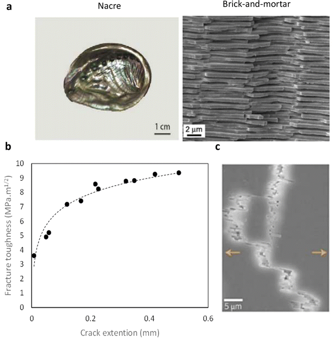 | ||
| Fig. 4 (a) The microstructure of the nacre inspires the development of biomimetic brick-and-mortar structures to bolster the mechanical properties of bone-like materials. By emulating nature's intricate design, implants can be crafted with enhanced strength and toughness, mirroring the hierarchical arrangement of mineral platelets and organic matrix in nacre. Reproduced from ref. 52 with permission from Elsevier, copyright 2018. (b) Fracture toughness based on a crack extension of natural nacre (data points extracted from ref. 52), shows the R-curve behavior of natural bone. (c) SEM image of the crack propagation path of the nacreous layer of seashell showing different toughening mechanisms. Reproduced from ref. 59 with permission from Springer Nature, copyright 2014. | ||
The fracture toughness of aragonite is typically around 1 MPa m½, while nacre can reach levels as high as 9 MPa m½. Fig. 4c shows the brick-and-mortar composition demonstrates a characteristic crack deflection post-initiation, a well-established toughening mechanism explored in earlier research. It is proposed that the overall toughening mechanism of nacre encompasses a synergistic integration of these multiscale mechanisms harmoniously.51,58
Table 2 summarizes the key characteristics of nacre, including its mechanical properties such as strength, toughness, and modulus of elasticity, as well as its unique microstructure.
| Description | |
|---|---|
| Microstructure | The brick-and-mortar microstructure, composed of aragonite (calcium carbonate) and organic matrix (a complex blend of proteins, polysaccharides, and glycoproteins) |
| Nano-sized aragonite platelets (thickness ∼0.3–0.5 μm; diameter ∼5–8 μm) embedded in an organic matrix, arranged in alternating layers (∼20 nm thick) | |
| Mechanical strength | Compressive strength ∼100–300 MPa |
| Flexural strength ∼100–210 MPa | |
| Fracture toughness | R-curve resistance behavior ∼2–9 MPa m1/2 |
| Young's modulus | A measure of the material's stiffness or rigidity ∼64–73 GPa |
| Biocompatibility and bioactivity | Nacre has shown the potential to promote bone formation without causing adverse reactions |
Fig. 5 presents Ashby plots illustrating the mechanical properties of various engineering materials in comparison to natural bone and nacre. These plots serve as crucial tools for understanding the trade-offs involved in material selection, particularly for biomedical applications such as bone implants.
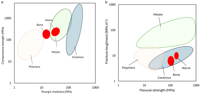 | ||
| Fig. 5 Exploring material strength: Ashby plot contrasts the mechanical properties of diverse materials with those of bone and nacre, offering insights into the relative performance and suitability for various engineering applications. (a) Compressive strength based on Young's modulus, (b) fracture toughness is based on Flexural strength. The data extracted from ref. 27, 29, 64–69. | ||
Fig. 5a depicts the relationship between compressive strength and Young's modulus. The plot reveals a critical insight: materials with high compressive strength often exhibit a correspondingly high Young's modulus. While high strength is desirable, an excessively high modulus can lead to stress shielding, a significant issue in bone implants. This reduction in load-bearing can cause bone resorption and potentially lead to implant failure. The plot clearly shows that metals and some ceramics like alumina, and zirconia, while possessing superior strength compared to bone, also have much higher Young's modulus, making them unsuitable for bone applications due to the risk of stress shielding. In contrast, natural nacre demonstrates a more balanced combination of compressive strength and Young's modulus, making them more functional in mimicking the mechanical environment of bone.27,60,61
Fig. 5b illustrates the relationship between fracture toughness and flexural strength. This plot underscores the inherent difficulty in simultaneously achieving high fracture toughness and high flexural strength in engineering materials. Natural nacre once again exhibits superior properties in this regard, balancing toughness and strength in a manner that many synthetic materials fail to achieve. This balance is particularly important for biomedical implants, where both toughness and strength are critical for durability and functionality.29,62,63
By graphically representing these mechanical parameters, engineers and researchers can visually assess the comparative performance of different materials against bone and nacre. To this end, scientists have developed ceramic composites that emulate its hierarchical organization. By integrating ceramic with organic matrices, nacre-like composites mimic the staggered arrangement and organic–inorganic interfaces observed in natural nacre. This biomimetic approach offers a promising avenue for creating bone implants with enhanced mechanical properties.63
4.2. Manufacturing of nacre-like composite materials
The fabrication of nacre-like composites involves replicating the hierarchical architecture and toughening mechanisms observed in natural bone tissue. At the core of this process, the mineral phase, typically CaP or other ceramics, is intricately assembled and bound by a polymeric matrix to create fundamental building blocks reminiscent of the mineralized collagen fibrils found in natural bone.70 This nanoscale arrangement is pivotal for emulating the strength and deformability exhibited by the mineralized collagen fibrils. However, due to the complexity, strategies are devised to mimic the toughening mechanisms observed in natural bone, such as integrating mineral bridges, nano-asperities, and viscoelastic layers within the composite structure as those found in nacre. Advanced fabrication techniques, including bi-directional freeze-casting (BFC), layer-by-layer assembly, electrospinning, and biomimetic mineralization, are commonly utilized to achieve the desired nano- and microscale architectures. The fabrication of nacre-like composites represents a burgeoning area of research, harnessing insights from biomimicry to natural materials with superior performance and adaptability.71,72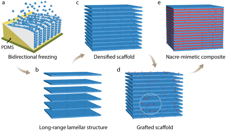 | ||
| Fig. 6 Fabrication steps for HA/PMMA composite with nacre–mimetic structure: (a) initially, create a scaffold by BFC of a HA slurry (20 vol% ceramic loading) on a copper cold finger, with a PDMS wedge inducing preferential ice crystal growth along its surface. (b) After sublimation and sintering, achieve an HA scaffold with extensive lamellar structure and around 70% porosity. (c) Densify the scaffold through uniaxial pressing to reduce porosity to approximately 15%–25%. (d) Enhance the ceramic–polymer interface by grafting methacrylate groups onto the HA surface. (e) Finally, obtain a nacre–mimetic composite by in situ polymerization of MMA within the grafted scaffold. Reproduced from ref. 75 with permission from Wiley-VCH Verlag GmbH & Co. KGaA, Weinheim, copyright 2015. | ||
Fig. 7 shows the microstructure of the HA/PMMA composite, the notable resemblance between the as-prepared HA/PMMA composite and natural nacre is underscored. The unpressed HA scaffold, characterized by a long-range aligned lamellar structure (a), is a result of BFC a feat challenging to achieve through conventional freeze-casting methods. Following uniaxial pressing, the HA scaffold undergoes significant densification, with the lamellar layers breaking into distinct ceramic “bricks” measuring approximately 5–20 μm thick and 10–110 μm long (b and c). Upon infiltration of the densified porous scaffolds with PMMA, the final HA/PMMA composites exhibit a hierarchical architecture akin to nacre, boasting 75–85 vol% ceramic content over multiple length scales (d and e). Notably, the inorganic bricks, parallel and closely packed throughout the sample, owe their uniformity to the BFC technique. Moreover, the asperities and roughness of the bricks closely mimic the inorganic bridges between aragonite platelets observed in natural nacre. Each layer of bricks is interspersed with polymer layers spanning from sub-micrometer to several micrometers in thickness (d). These structural intricacies are pivotal for the mechanical prowess demonstrated by Nacre.
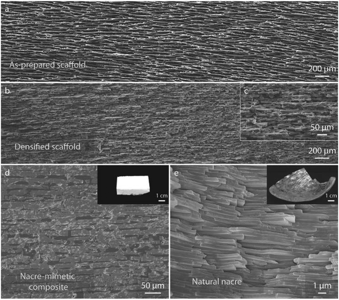 | ||
| Fig. 7 The SEM images depict the structural comparison between the nacre–mimetic HA/PMMA composite and natural nacre. (a) Illustrates the HA scaffold prepared through BFC, while (b) and (c) showcase the densified scaffold post-uniaxial pressing. (d) Presents the HA/PMMA composite fabricated via BFC and in situ polymerization, demonstrating a brick-and-mortar structure similar to (e) natural nacre. Note that while (d) and (e) aim to highlight structural similarities, they may differ slightly in magnification. Reproduced from ref. 75 with permission from Wiley-VCH Verlag GmbH & Co. KGaA, Weinheim, copyright 2015. | ||
Following sublimation and sintering, an HA scaffold displaying a long-range lamellar structure with 70% porosity was achieved. Subsequent densification through uniaxial pressing reduced the porosity to approximately 20–40%. The impact of the ceramic fraction on wall thickness, density of ceramic bridges, and compressive strength is illustrated in Fig. 8a. Increasing the ceramic fraction from 60 vol% to 80 vol% resulted in a rise in wall thickness from 17.89 to 36.01 μm, accompanied by increased bridge density and compressive strength, reaching 23.03% and 167.5 MPa, respectively. The formation of ceramic bridges arises from the conflict between forced and preferential ice growth during bidirectional freeze-casting, leading to an oblique ice growth direction.78,79 b–d provide microstructural insights into composites at ceramic fractions of 60 vol%, 70 vol%, and 80 vol%, respectively. Augmented ceramic fractions correlate with longer and thicker walls, along with the heightened density of ceramic bridges, crucial for enhancing strength and toughness. These bridges facilitate stress transfer, redistribute forces, and augment frictional sliding between ceramic layers, thereby improving overall mechanical.
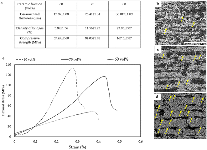 | ||
| Fig. 8 (a) Variation of ceramic fraction impacts ceramic wall thicknesses, ceramic bridge density, and compressive strength. The increase from 60 vol% to 80 vol% yields thicker walls at 36.01 ± 1.89 μm, heightened ceramic bridge density at 23.03 ± 2.07 (%), and increased compressive strength at 167.5 ± 2.87 MPa. Microstructure analysis of the composite at 60 vol%, 70 vol%, and 80 vol% ceramic fractions is presented in (b–d) respectively (scale bars: 500 μm). (d) Yellow arrows denote the increase in ceramic bridges with higher ceramic fractions. (e) Illustrates the stress–strain relationship of different composites with varying ceramic fractions, demonstrating a flexural strength of 130 ± 5.82 MPa and Young's modulus of 19.75 ± 2.38 GPa for composites with 80 vol% HA. Reproduced from ref. 78 with permission from MPDI, copyright 2023. | ||
Recently, a novel nacre-mimetic composite endowed with inherent self-healing and shape-programming capabilities was presented. Initially, alumina platelets were organized into a scaffold featuring lamellar layers utilizing the bidirectional freeze-casting method. Mechanical responses of natural nacre (Fig. 9c), ‘artificial-nacre’ infiltrated with conventional thermoplastic PMMA (d), and the self-healable ‘Smart nacre’ produced by infiltration of Diels–Alder network polymer the densified alumina scaffold in its liquid precursor form followed by thermal curing. (e) Were comparatively evaluated. Notably, while natural nacre and nacre-like infiltrated with thermoplastic PMMA exhibited non-healable properties, only the nacre-like demonstrated self-healing capability, with stress–strain curves nearly fully recovered post-healing.80
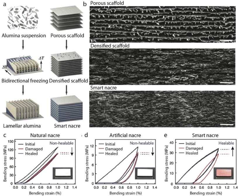 | ||
| Fig. 9 Self-healing nacre-mimetic composites: (a) schematic representation of the fabrication process for smart nacre, involving the infiltration of a long-range aligned alumina scaffold with a thermally responsive dynamic polymer network. (b) Scanning electron microscope (SEM) images depicting the porous alumina scaffold, densified scaffold, and smart nacre. Stress–strain curves were obtained during the damage-healing process for natural nacre (c), nacre-like infiltrated with a non-healable polymer (d), and smart nacre (e). Insets display optical images corresponding to the respective samples. Scale bars in (c–e) represent 2 cm. Reproduced from ref. 80 with permission from Springer Nature, copyright 2019. | ||
Fig. 10 shows the schematic of nacre-like composite preparation via the self-assembly technique. At the nanoscale to microscale assembly level, large-area 2D nacre-mimetic films were synthesized from a homogeneous mixture of brushite platelets and sodium alginate (SA) solution through water evaporation-induced self-assembly. The abundant carboxyl and hydroxyl groups present on the molecular chain of SA facilitate interfacial interactions between the brushite platelets and SA via Ca2+–SA coordination. Fig. 10c and d show the SEM images of natural nacre and self-assembled nacre-like composite.84
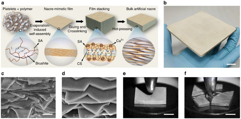 | ||
| Fig. 10 Fabrication and assessment of bulk synthetic nacre. (a) Schematic representation illustrating the bottom-up assembly process of bulk synthetic nacre. (b) Display of large-scale fabricated bulk synthetic nacre. Scale bar: 2 cm. (c and d) Examination of cross-sections of the synthetic nacre (c) and natural Cristaria plicata nacre (d) revealing comparable fractured layered microstructures. Scale bars: 1 μm. (e and f) Comparative visualizations of synthetic nacre (e) and Cristaria plicata nacre (f) subjected to equivalent impact forces, highlighting the enhanced impact resistance of the synthetic nacre. Scale bars: 5 mm. Reproduced from ref. 84 with permission from Springer Nature, copyright 2017. | ||
Fig. 11 shows the self-assembled clay/PVA films which were laminated after drying to prepare a nacre-like composite. It shows the schematic of the whole process and the final microstructure images taken with transmission electron microscopy (TEM), show a highly aligned structure at a 40 nm scale. In the process of preparing the nacre-like clay/polymer composite depicted schematically, polyvinyl alcohol (PVA)-coated clay nano-platelets undergo self-assembly during evaporation, resulting in the formation of films approximately 60 μm thick. Subsequently, these films are fused through a simple lamination process. The resultant plates, which are 12 cm wide and have a thickness ranging from 3 to 10 mm, are then available for shaping into desired configurations for testing purposes. Additionally, TEM illustrates the aligned bulk nanostructure with a periodicity of 2.6 nm, showcasing the organization achieved through self-assembly. This process underscores the effective utilization of self-assembly techniques in fabricating composite materials with desired properties and structures resembling natural nacre.85
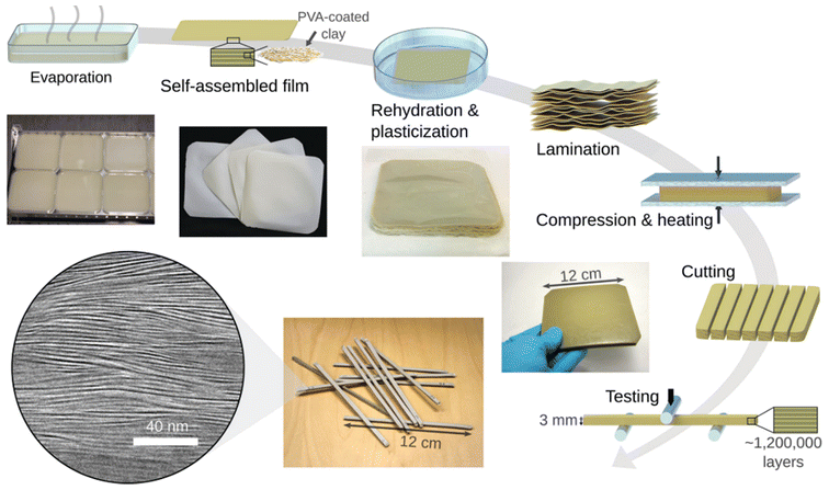 | ||
| Fig. 11 The schematic of preparing the nacre-like clay/polymer composite via self-assembly technique. During evaporation, polyvinyl alcohol (PVA)-coated clay nano-platelets undergo self-assembly to form films with a thickness of approximately 60 μm. These films are then fused using a straightforward lamination process. The resulting plates, measuring 12 cm in width and 3–10 mm in thickness, can be cut into desired shapes for testing purposes. TEM displayed at the bottom left, exhibits the aligned bulk nanostructure with a periodicity of 2.6 nm. Reproduced from ref. 85 with permission from Wiley-VCH Verlag GmbH & Co. KGaA, Weinheim, copyright 2017. | ||
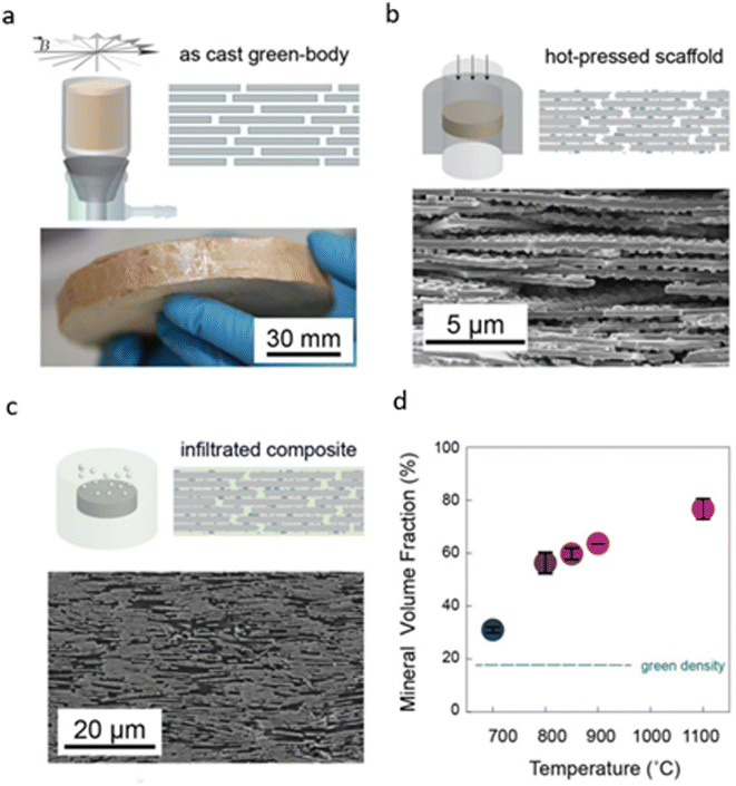 | ||
| Fig. 12 Production of nacre-like composites via vacuum-assisted magnetic alignment (VAMA). (a) Magnetized titania-coated alumina platelets are aligned by a rotating magnetic field, followed by vacuum consolidation into green bodies of bulk ceramic. (b) Hot pressing of green bodies yields sintered porous ceramic scaffolds with surface asperities and mineral bridges. (c) Infiltration with low-viscosity thermoset monomers under vacuum or pressure forms dense polymer–ceramic composites. (d) Increased sintering temperature enhances the composite density. Reproduced from ref. 86 with permission from Wiley-VCH Verlag GmbH & Co. KGaA, Weinheim, copyright 2016. | ||
External pressure during sintering is crucial for forming robust mineral contacts, as pressureless sintering results in scaffolds with lower density and mechanical integrity. In contrast, hot-pressing yields denser scaffolds with a high density of interfacial contact points between the aligned platelets, achieving a tunable microstructure resembling the desired brick-and-mortar structure, as depicted in Fig. 12d.
The large-scale fabrication process of nacre-like ceramic–resin composites encompasses three principal stages illustrated in Fig. 13a. Initially, scalable nacre-like composite films are generated through the implementation of a continuous fiber-assisted evaporation-induced self-assembly method depicted in Fig. 13b. Following this, layered ceramic scaffolds are prepared via a pressure-less sintering procedure after the lamination of the composite films. Lastly, the ultimate products are attained through a resin infiltration and curing procedure.
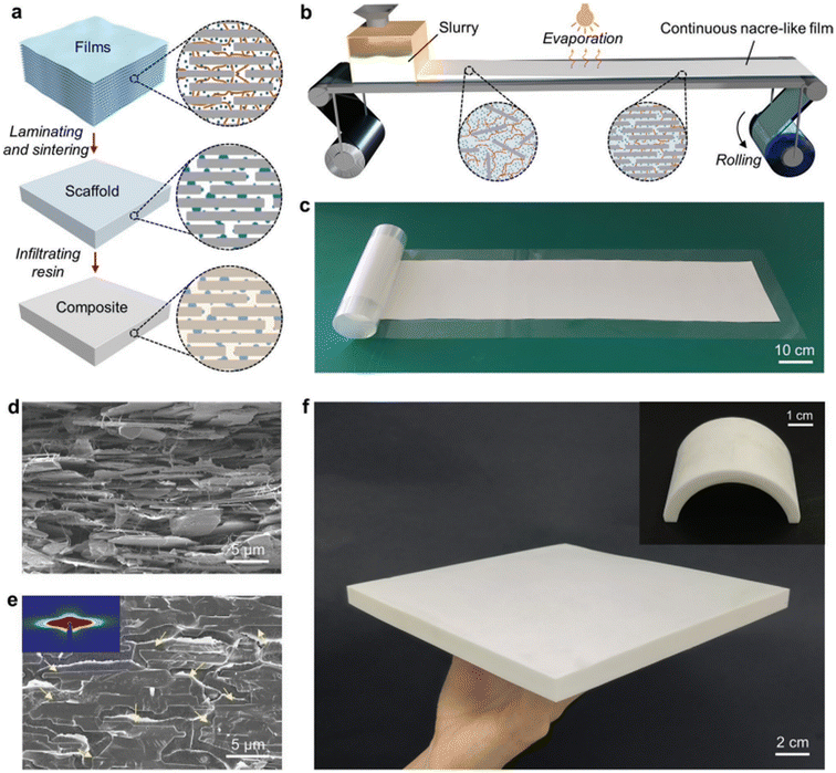 | ||
| Fig. 13 Large-scale fabrication of nacre-like composites. (a) Schematic illustration outlining the process for large-scale production of nacre-like ceramic–resin composites. Alumina microplatelets, BC nanofibers, and kaolin particles are represented by gray rectangles, brown curves, and blue dots, respectively. (b) Schematic depiction illustrating the continuous preparation of nacre-like composite film using a nanofiber-assisted evaporation-induced self-assembly method. (c and d) Photograph (c) and cross-sectional SEM image (d) of a large-scale nacre-like composite film prepared through continuous fiber-assisted evaporation-induced self-assembly as described in (b). (e) SEM image displaying the cross-section of a nacre-like ceramic–resin composite, with yellow arrows highlighting the boundaries of alumina microplatelets aligned in the polymer matrix. The insert exhibits a small-angle X-ray scattering image of the nacre-like ceramic scaffold before polymer infiltration. (f) Photographs demonstrating a large-sized nacre-like ceramic–resin composite and a molded nacre-like ceramic–resin composite with an arch shape. Reproduced from ref. 87 with permission from Wiley-VCH Verlag GmbH, copyright 2023. | ||
Fig. 13d depicts the SEM image of alumina microplatelets self-assemble into a well-aligned layered structure interconnected by the bacterial cellulose (BC) network, with kaolin microparticles homogeneously dispersed amongst them in the films prepared on both continuous polyethylene terephthalate (PET) substrates. Notably, despite containing an exceptionally high mass ratio (approximately 95 wt%) of rigid inorganic constituents, the resulting film exhibits remarkable flexibility rather than brittleness. This flexibility is attributed to the facilitating role of the flexible 3D BC network and the porous layered structure within the films, which permit the alumina micro platelets to adjust their positions appropriately during the bending process.
Furthermore, this property, coupled with the satisfactory tensile strength of the composite films, proves advantageous for post-processing and facilitates the realization of complex shape designs through compression molding. The simplicity and efficacy of the one-step nanofiber-assisted self-assembly method present opportunities for facile scale-up and customization of the final materials. Following film production, the composite films are uniformly cut to size and stacked together. A subsequent pressing step is undertaken to enhance their flatness and compactness, ensuring close contact between layers. The laminate is then subjected to pressure-less sintering, distinct from previously reported hot-pressing sintering methods, which necessitate high pressure, specific furnaces, and customized molds during the sintering process. The sintered kaolin microparticles function as mineral bridges, effectively welding both the macro-level interfaces of the stacked films and the micro-level interfaces of the alumina microplatelets. Ultimately, Fig. 13e depicts a densified ceramic–resin composite featuring a highly ordered nacre-like architecture achieved post-infiltration and curing of poly(methyl methacrylate) (PMMA) into the porous ceramic scaffold. The low viscosity of methyl methacrylate (MMA) monomer and its compatibility with the ceramic scaffolds enable uniform resin infiltration. This scalable strategy facilitates the fabrication of large-sized samples with high production efficiency as illustrated in Fig. 13f. Moreover, the size, thickness, morphology, and spatial composition of the ultimate products can be manipulated as desired. For instance, an arch-shaped nacre-like ceramic–resin composite with alumina microplatelets well aligned along the tangent of the arch can be readily obtained using a specific pre-pressed mold refer to Fig. 13f. The achieved nacre-like ceramic–resin composites, characterized by scalable size and moldable capacity, pose challenges to be manufactured by previously developed methods. Remarkably, the bottom-up processing strategy facilitates facile yet precise control of local microstructures and constituents by stacking various films with specific microstructures and constituents in a pre-designed sequence.87
In another study, the structural merits of both enamel (highly ordered nanorod bundles) and nacre (brick-and-mortar structure) were combined to construct a new kind of highly ordered ultralong HA nanowire fiberboard-and-mortar alignment hierarchical structure (HFMAS) by the multiscale and multilevel assemblies of ultralong HA nanowires from the nanoscale to microscale to macroscale and from 1-D to 2-D to 3-D shown in Fig. 14a and b. Through a series of multiscale and multilevel self-assembly processes, the HFMAS nanocomposite with a highly ordered hierarchical architecture can be prepared, spanning from the nanoscale to the microscale to the macroscale, and from 1-D to 2-D to 3-D levels (as illustrated in Fig. 14b). These ultralong HA nanowires exhibit a preference for growth along the c-axis of the crystal lattice, subsequently self-assembling into HA nanowire bundles along the longitudinal direction of the ultralong HA nanowires (1-D, 1st level ordering) at the nanoscale. Following this, aided by the shear force resulting from the injection of the HA nanowire paste, the HA nanowire bundles align preferentially along their longitudinal direction to form macroscale fibers. The width of the resulting fiber is dictated by the diameter of the injecting needle, while the length of the fiber is variable, contingent upon the available quantity of the HA nanowire paste. Finally, polymers infiltrate the interstices within the entire framework of the HA nanowire bulk sample, culminating in the formation of the highly ordered ultralong HFMAS depicted in Fig. 14c–e.88
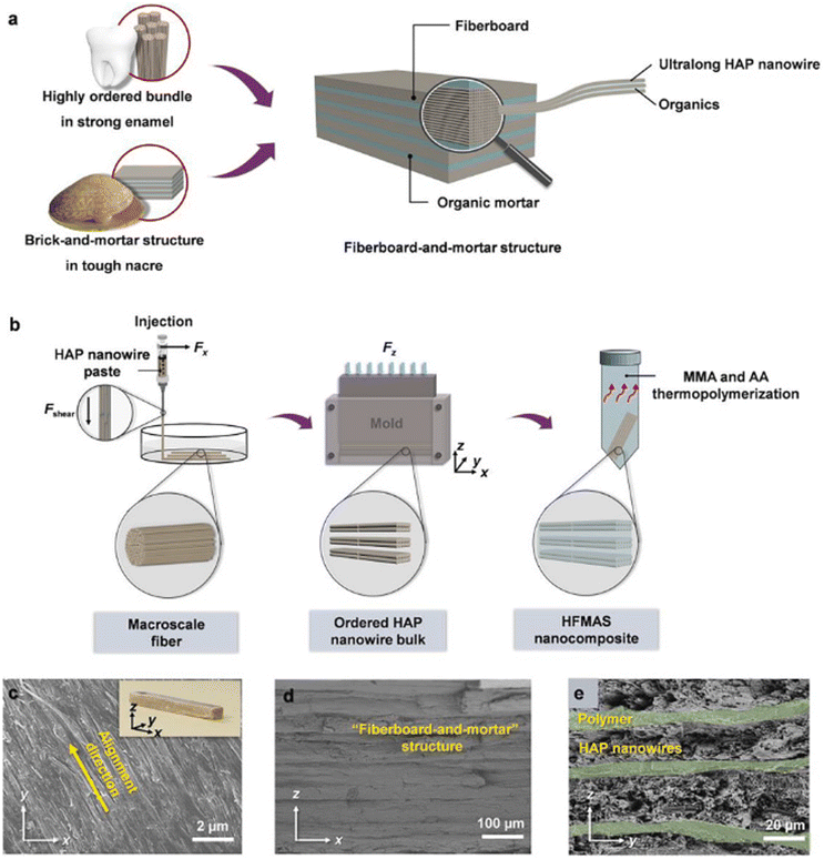 | ||
| Fig. 14 Structural design, construction, and characterization of the prepared HFMAS nanocomposite. (a) Schematic depiction illustrating the design of the fiberboard-and-mortar structure, drawing inspiration from the resilient enamel and robust nacre; the structure demonstrates multiple levels of ordering spanning from the nanoscale to the macroscale. (b) Schematic illustration outlining the synthesis process of the HFMAS nanocomposite. (c–e) Scanning electron microscopy (SEM) images showcasing the highly organized fiberboard-and-mortar structure of the HFMAS nanocomposite. The fiberboard thickness measures 20–30 μm, while the polymer layer is approximately 5 μm thick. The inset of (c) provides a digital image of a sample of the HFMAS nanocomposite. Reproduced from ref. 88 with permission from Elsevier, copyright 2020. | ||
Table 3 lists examples of various nacre-like composite materials, scaffold fabrication methods, and their corresponding mechanical properties. Different studies have explored the impact of material composition and fabrication techniques on scaffolds’ mechanical strength, stiffness, and toughness. BFC is a commonly used method, as seen in multiple studies. For example, Bai et al. reported that a HA/polymethylmethacrylate (PMMA) composite produced by this method achieved a flexural strength of approximately 100 MPa and a Young's modulus of 20 GPa.75 By adding polyacrylic acid (PAA) to the HA/PMMA matrix, resulting in a flexural strength of 158 ± 7.02 MPa, Young's modulus of 24 ± 4.34 GPa, and a fracture toughness of 5.27 ± 1.03 MPa m1/2. This enhancement underscores the role of the composite's composition in improving mechanical properties.78 Du et al. also utilized BFC to fabricate an Al2O3/Diels–Alder polymer network composite. This scaffold displayed a lower flexural strength of 62.2 ± 5.8 MPa and Young's modulus of 3.6 ± 0.5 GPa, highlighting the influence of material choice on mechanical performance. Unlike the previous examples, this composite did not report a fracture toughness value, indicating a possible limitation in its mechanical evaluation.80 In contrast, self-assembly methods have also shown promise. For example, Gao et al. reported that a brushite/chitosan composite fabricated using this method achieved a high flexural strength of approximately 267 MPa and Young's modulus of 18.6 GPa, alongside a fracture toughness of about 8.7 MPa m1/2.84 Similarly, Morits et al., explored a Clay/PVA composite using self-assembly, which exhibited a flexural strength of 220 MPa, Young's modulus of 25 GPa, and fracture toughness of 3.4 MPa m1/2.85 These results suggest that self-assembly can produce scaffolds with robust mechanical properties. Magnetic alignment and vacuum-assisted assembly are other notable methods. Grossman et al. utilized this technique to fabricate an Al2O3/PVA + PAA composite, which achieved an impressive flexural strength of 350 MPa and a Young's modulus of 38.88 GPa. Although fracture toughness was not reported, the high flexural strength indicates a significant advantage in mechanical reinforcement through this fabrication method.86 Lastly, advanced methods such as bottom-up combining nanofiber-assisted evaporation-induced self-assembly and extrusion-based 3D-printing are also highlighted. Monia et al. demonstrated that a ceramic (Kaolin clay + alumina micro-platelets)/PMMA composite produced using the former technique achieved a flexural strength of 292 MPa and a fracture toughness of 6.4 MPa m1/2.89
| Composite materials | Scaffold fabrication methods | Flexural strength (MPa) | Young's modulus (GPa) | Fracture toughness (MPa m1/2) | Ref. |
|---|---|---|---|---|---|
| HA/PMMA | BFC | ∼100 | ∼20 | — | Hao et al. (2016)75 |
| HA/PMMA + PAA | BFC | 158 ± 7.02 | 24 ± 4.34 | 5.27 ± 1.033 | Tabrizian et al. (2023)78 |
| Al2O3/Diels–Alder polymer network | BFC | 62.2 ± 5.8 | 3.6 ± 0.5 | — | Du et al. (2019)80 |
| Brushite/SA/chitosan(CS) | Self-assembly | ∼267 | ∼18.6 | ∼8.7 | Gao et al. (2017)84 |
| Clay/PVA | Self-assembly | 220 | 25 | 3.4 | Morits et al. (2017)85 |
| Al2O3/PVA + PAA | Magnetic alignment and vacuum-assisted assembly | 350 | 38.88 | — | Grossman et al. (2017)86 |
| Ceramic (kaolin clay + alumina micro-platelets)/PMMA | Bottom-up combining nanofiber-assisted evaporation-induced self-assembly | 292 | — | 6.4 | Zhang et al. (2023)89 |
| HAnw/PMMA + PAA | Extrusion-based 3D-printing | 308 | 34.7 | 4.77 | Yu et al. (2020)88 |
Yu et al. used extrusion-based 3D-printing to fabricate a HA nanowires (HAnw)/PMMA + PAA composite, which resulted in a flexural strength of 308 MPa, a Young's modulus of 34.7 GPa, and a fracture toughness of 4.77 MPa m1/2. These methods highlight the potential for producing highly tailored and mechanically robust scaffolds suitable for bone tissue engineering.88–90
Overall, Table 3 illustrates the significant impact that both the choice of constituent materials and fabrication techniques have on the mechanical properties of nacre-like composites, with different methods offering various advantages depending on the desired applications.
5. Mechanical and microstructural characterization of nacre-like CaP/polymer composite for bone implant applications
After reviewing various methodologies for developing nacre-like composites across different materials, with an emphasis on their structures and fabrication techniques, Fig. 15 illustrates the mechanical properties of different nacre-like CaP/polymer composites used in bone implant applications. These composites are compared based on the flexural strength (MPa) and Young's modulus (GPa).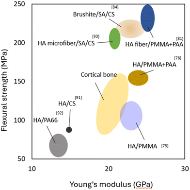 | ||
| Fig. 15 Ashby plot of flexural strength and Young's modulus for the biomimetic composites compared with natural cortical bone. | ||
The HA/SA/CS composite demonstrates lower flexural strength and Young's modulus compared to cortical bone, indicating limited mechanical support.91 However, composites such as HA/polyamide (PA66) show properties more aligned with cortical bone, suggesting moderate potential for effective load-bearing applications.92 Notably, HA/PMMA variants, including HA/PMMA + acrylic acid (PAA) and HA fibre/PMMA + PAA, exhibit higher flexural strength and Young's modulus, indicating enhanced mechanical performance. Although these values exceed those of cortical bone, they are designed to replicate the staggered, organic–inorganic interfaces found in nacre.75,78,88 Composites like HA microfibre/CS and brushite/SA/CS exhibit promising flexural strength while maintaining Young's modulus close to that of natural bone.84,91,93
By emulating the hierarchical structure and organic–inorganic interfaces observed in natural nacre, these biomimetic composites can enhance bone implants’ strength, toughness, and fracture resistance. This biomimetic approach demonstrates that it is possible to develop composites with high strength and toughness that match the properties of cortical bone. Consequently, compared to traditional engineering materials shown in Fig. 5, these nacre-inspired composites effectively solve the stress shielding problem, offering a significant advancement in the development of bone implants.
In addition to flexural strength and Young's modulus, the fracture toughness value significantly influences the effectiveness of bone implants. Fig. 16 shows the fracture toughness based on crack extension in different nacre-like composites. HA/PMMA + PAA composite exhibits a rising R-curve behavior, with the average value of fracture toughness of 5.27 ± 1.033 MPa m1/2, however, for the composite of brushite/SA/CS, the maximum fracture toughness, KJ, of the nacre-like composite, is increased by more than three times from the crack initiation (1.9 MPa m1/2) to the end of the stable crack propagation (8.7 MPa m1/2), which surpasses that of natural nacre. These results strongly illustrate that the nacre-like possesses both high strength and toughness similar to natural structural materials, which can be attributed to the multiscale replication of the hierarchical brick-and-mortar structure of natural nacre. Biomimetic designs, enabled by micro/nanoscale manipulation and scalable fabrication, are shown to create new strong and tough structural materials.
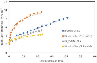 | ||
| Fig. 16 Rising R-curves for the selected composites. Data points extracted from.78,81,84,88 | ||
Table 4 provides a comparative overview of three fabrication techniques for nacre-like composites, highlighting their advantages, disadvantages, and effects on microstructure. BFC is particularly effective in replicating the layered, lamellar structure characteristic of natural nacre. This technique enables controlled alignment and mineral bridging, both crucial for creating composites that closely resemble nacre. However, to achieve optimal mechanical properties, additional steps are needed to address the inter-wall gaps between ceramic layers. Moreover, precise control over these gaps and the distribution of mineral bridges remains challenging. The process requires careful management of freezing conditions, which significantly influences the anisotropic, lamellar microstructure and controlled porosity, primarily at the micro-scale.75,78
| Fabrication technique | Advantages | Disadvantages | Effect on microstructure |
|---|---|---|---|
| Bi-directional freeze-casting | - Creates highly aligned, lamellar structures | - Complex and time-consuming process | - Produces a layered, nacre-like microstructure with well-defined interfaces between layers |
| - Mimics the layered structure of the nacre effectively | - Requires precise control of freezing conditions | - Can achieve high structural integrity and alignment | |
| - Limited scalability | |||
| Self-assembly (layer-by-layer assembly) | - Simple and low-cost method | - Limited to specific types of materials | - Can create nacre-like structures by exploiting natural self-assembly, leading to hierarchical organization |
| - Capable of creating intricate structures | - May require additional steps for stabilization | - Variable microstructure due to less precise control | |
| - Scalable | |||
| Extrusion-based 3D-printing | - High customization and precision | - Resolution limits can affect microstructure detail | - Allows for precise control over the geometry and arrangement of nacre-like structures |
| - Scalable and suitable for complex geometries | - Requires post-processing to achieve a nacre-like structure | - Microstructure can be tailored but may need optimization to match natural nacre | |
| - Can integrate multiple materials and phases | - May have issues with material bonding | ||
In contrast, self-assembly (layer-by-layer assembly) excels in creating highly ordered nano- and microstructures from platelets and flakes that closely mimic nacre's hierarchical organization. This method also allows for the direct incorporation of functional materials, such as growth factors, enhancing the biological performance of nacre-like composites. Despite its effectiveness in replicating the nacre's intricate structure, self-assembly faces material source limitations, as the platelets and flakes must be synthesized. However, in terms of the fabrication process, self-assembly is more cost-effective and easier to scale up compared to BFC.84,85
Extrusion-based 3D-printing offers significant design flexibility, making it well-suited for creating complex, customized nacre-like geometries. It integrates seamlessly with computer-aided design (CAD) systems, enabling precise control over scaffold architecture. However, 3D-printing faces resolution constraints that hinder the replication of fine nacre-like features. The process requires careful optimization of parameters and can be costly in terms of both equipment and materials. Typically, it starts with wires or fibers that require pre-processing, such as material synthesis. While 3D printing achieves detailed microstructures with micron to sub-micron precision, replicating accurate nano-scale features akin to natural nacre remains challenging.88,93
In summary, each fabrication method has distinct strengths and limitations when it comes to creating nacre-like composites. BFC is effective for producing lamellar structures but faces challenges related to time and scalability. Self-assembly offers high precision and is scalable in terms of the fabrication process, but requires starting materials like platelets and flakes. Extrusion-based 3D-printing provides flexibility and rapid prototyping but is limited by resolution and cost. The choice of method should be guided by the specific requirements needed to replicate nacre's unique geometries.
Fig. 17 shows SEM images of various nacre-like composites fabricated using different methodologies and material morphologies. In Fig. 17.1, HA/PMMA composites fabricated via BFC exhibit enhanced fracture toughness. Crack deflection at ceramic–polymer interfaces and extrinsic toughening mechanisms, such as stretching and tearing of polymeric “mortar” layers, contribute to this enhancement. Overall, the observed crack bridging and pull-out mechanisms significantly enhance the work of fracture compared to pure HA. Similar to natural nacre, damage in bioinspired hybrid ceramic materials, like HA/PMMA composites, isn't solely localized at the crack tip but distributed ahead of the advancing crack. Extrinsic toughening mechanisms facilitate stable (subcritical) crack growth, contrasting with the unstable (catastrophic) cracking in monolithic ceramics like pure HA (Fig. 17.1.b and c). This ability to employ extrinsic toughening is fundamental to the potential damage tolerance of these composites.90,91
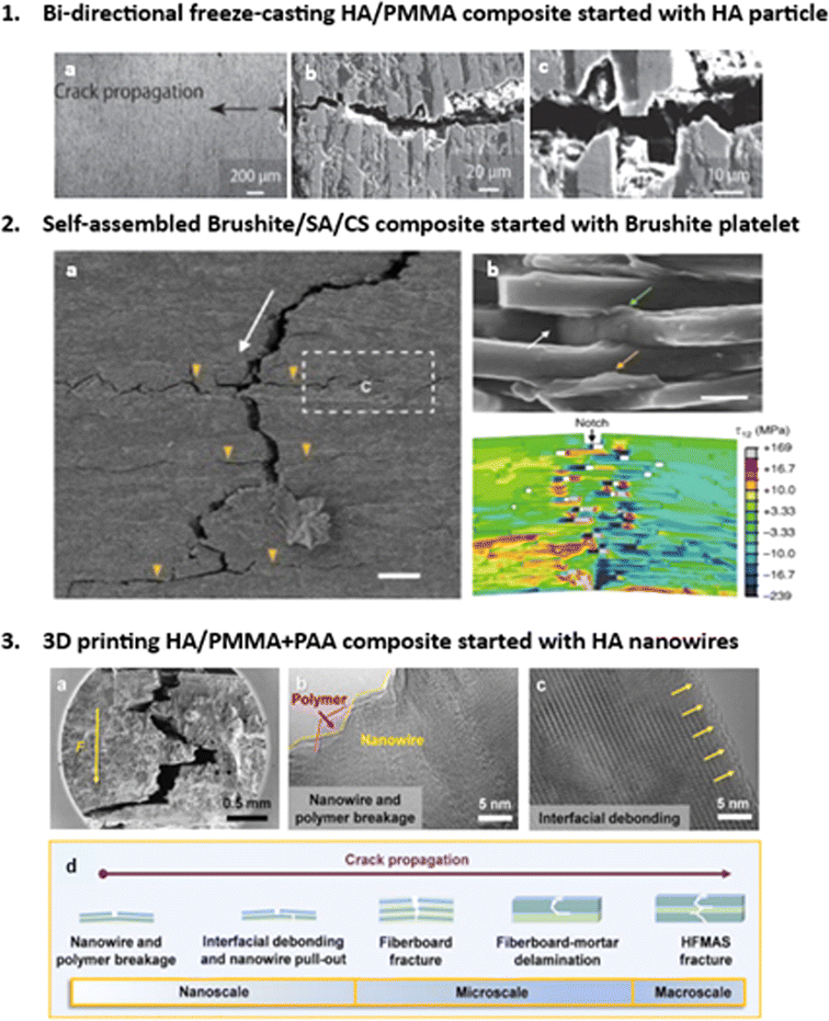 | ||
| Fig. 17 Microstructural characterization of crack propagation paths for different nacre-like composites fabricated with different methodologies, (1) The nacre-like composite fabricated via BFC started from HA particles. Reproduced from ref. 75 with permission from Wiley-VCH Verlag GmbH & Co. KGaA, Weinheim, copyright 2015, (2) brushite platelet prepared nacre-like composite via self-assembly. Reproduced from ref. 84 with permission from Springer Nature, copyright 2017, (3) HA nanowires nacre-like composites with extrusion-based 3D-printing. Reproduced from ref. 88 with permission from Elsevier, copyright 2020. | ||
Fig. 17.2a illustrates the initiation and propagation of cracks within the nacre-like, demonstrating a characteristic tortuous path, known as crack deflection. This phenomenon is accompanied by significant interface failure, a prominent extrinsic toughening mechanism observed in both natural materials and bioinspired structural counterparts. On the fracture surface (Fig. 17.2b), a densely adhered polymer layer to the platelets’ surfaces is evident, indicating robust platelet–SA interfacial interactions. Additionally, distinct instances of polymer bridging, stretching from interface failure, and cavity formation due to platelets’ pull-out are observed (Fig. 17.2b). These mechanisms facilitate efficient energy dissipation through frictional sliding and polymer matrix breakage upon crack encounter with the platelet–polymer interface. Fig. 17.2a depicts the crack propagation path in a nacre-like composite initiated with brushite platelets, fabricated via the self-assembly method. The collective action of proposed extrinsic toughening mechanisms redistributes applied load, alleviating locally high stresses across various length scales. This contributes to the observed rising R-curve behavior in the nacre-like (Fig. 17). Extrinsic toughening, stemming from the hierarchical “BM” architecture, plays a pivotal role in load redistribution and toughness enhancement within the nacre-like. Subsequent interface failure, dominated by sliding with friction, plasticity, platelets’ pull-out, and daughter microcrack nucleation and branching, constitutes crack bridging at a larger scale (Fig. 17.2b).84
Fig. 17.3a–c displays the composite initiated with HA nanowires. The substantial content of ultralong HA nanowires in the HFMAS nanocomposite suggests their pivotal role in load support, stress dispersion, and inhibition of crack propagation within the composite. Oriented fibers in composite materials are known to effectively dissipate energy. Cracks within the HFMAS nanocomposite follow a tortuous path along the direction of force propagation (Fig. 17.3a), indicating crack deflection, a primary toughening mechanism contributing to high fracture resistance. As cracks transition from accessible to constrained directions, the resistance force against crack formation significantly amplifies, inducing a toughening effect. Under external loading, polymers within the nanocomposite deform in a stepwise manner, absorbing substantial energy and enhancing toughening performance. Extending the path of crack propagation dissipates more energy, mitigating damage to the structural integrity of the nanocomposite.88
Fig. 17.3b and c present high-resolution TEM images of fracture features of ultralong HA nanowires and polymer components, showing interfacial debonding between nanowires and polymer. This phenomenon increases the difficulty of rupturing the fiber–polymer interface, enhancing fracture resistance. Notably, crack phenomena are observed perpendicular to the loading direction, providing evidence for the superior fracture resistance of the HFMAS nanocomposite. Fig. 17.3d illustrates a schematic of crack deflection and twisting during propagation from macro to nano-scale, depicting nanowire and polymer breakage, interfacial debonding, nanowire pull-out in the nano-scale, and fiber-board fracture and delamination in the micro-scale, ending with HFMAS fracture in the macro-scale.88
All nacre-like composites, regardless of fabrication methodologies and morphologies of starting materials, exhibit crack deflection and twisting. This tortuous crack propagation path, reminiscent of natural nacre, highlights the composite's resilience and fracture resistance. Strong interfacial interactions between nanowires and the polymer matrix, coupled with crack deflection mechanisms, significantly contribute to the material's ability to withstand external stresses. Additionally, the stepwise deformation of polymers under loading enhances energy absorption, further enhancing toughening performance. The hierarchical nacre-like structure enables effective crack twisting and deflection, resembling mechanisms observed in natural nacre.
6. Conclusion and future prospectives
This review has explored the progress and ongoing challenges in bone implant materials. Traditional options like stainless steel and titanium are recognized for their high strength. Still, they often lead to other unwanted properties such as stress shielding issues because their stiffness differs significantly from that of natural bone. This difference can weaken the surrounding bone and ultimately lead to implant failure. In contrast, nacre-like ceramic composites show great promise as an alternative. These materials are designed to mimic the natural, layered structure of nacre, or mother-of-pearl, which provides an impressive combination of strength and toughness. By replicating this natural design, nacre-like composites could potentially address some of the shortcomings of traditional implant materials, such as stress shielding, and improve bone implants’ overall performance and durability.Despite promising developments and efforts to use natural nacre as bone implants, there remains a significant gap in current research. So far, there are no case studies or clinical trials reported on using nacre-like composites in actual bone defect treatments. Most existing studies have concentrated on the fabrication and mechanical properties of these materials, demonstrating their potential similarity to natural bone in terms of mechanical and microstructural characteristics. However, the real-world application of these materials for treating bone defects remains largely unexplored.
To advance this field, several key areas require further research. First, there is a need for more investigations into the long-term properties of these composites, particularly in conditions that mimic the real bone environment. While most studies are conducted in a dry state, it is crucial to explore the behavior of these materials in a wet state, similar to that of actual bone. In terms of fabrication, there is also room for improvement in controlling microstructure, scalability, and cost, which would enhance the functionality and efficiency of these composites as bone implants.
Furthermore, in vivo studies are necessary to validate the biocompatibility and bioactivity of nacre-like composites. Bridging the gap between laboratory findings and clinical practice is essential. Interdisciplinary collaboration will be vital in translating these advancements into clinical solutions. Cooperation among materials scientists, engineers, biologists, and clinicians will help address practical challenges and ensure that new materials meet the rigorous demands of clinical applications.
Data availability
As this manuscript is a review paper, it does not contain original experimental data. Instead, all data referenced in this manuscript have been extracted from previously published sources. The relevant datasets and research findings can be accessed through the cited references.Conflicts of interest
The authors declare that there are no conflicts of interest to disclose.References
- H. Le Ferrand and C. E. Athanasiou, A Materials Perspective on the Design of Damage-Resilient Bone Implants Through Additive/Advanced Manufacturing, JOM, 2020, 72(3), 1195–1210, DOI:10.1007/s11837-019-03999-3.
- M. P. Ginebra, M. Espanol, Y. Maazouz, V. Bergez and D. Pastorino, Bioceramics and bone healing, EFORT Open Rev., 2018, 3(5), 173–183, DOI:10.1302/2058-5241.3.170056.
- A. Warburton, S. J. Girdler, C. M. Mikhail, A. Ahn and S. K. Cho, Biomaterials in spinal implants: A review, Neurospine, 2020, 17(1), 101–110, DOI:10.14245/ns.1938296.148.
- M. P. Binitha and P. P. Pradyumnan, Dielectric Property Studies of Biologically Compatible Brushite Single Crystals Used as Bone Graft Substitute, J. Biomater. Nanobiotechnol., 2013, 4(2), 119–122, DOI:10.4236/jbnb.2013.42016.
- K. L. Corbett, E. Losina, A. A. Nti, J. J. Z. Prokopetz and J. N. Katz, Population-based rates of revision of primary total hip arthroplasty: A systematic review, PLoS One, 2010, 5(10), 1–8, DOI:10.1371/journal.pone.0013520.
- A. S. da S. Mello, P. L. dos Santos, A. Marquesi, T. P. Queiroz, R. Margonar and A. P. de Souza Faloni, Some aspects of bone remodeling around dental implants, Revista Clínica de Periodoncia, Implantología y Rehabilitación Oral, 2016, 1–9, DOI:10.1016/j.piro.2015.12.001.
- C. Ching-Lung, A. Seng Bin, C. Manoj and C. Eddie Siu-Lun, et al., An updated hip fracture projection in Asia: The Asian Federation of Osteoporosis Societies study, Osteoporos. Sarcopenia., 2018, 4(1), 16–21, DOI:10.1016/j.afos.2018.03.003.
- E. Sanchez-Gonzalez, F. Rodriguez-Rojas, E. Pinilla-Cienfuegos, O. Borrero-Lopez, A. L. Ortiz and F. Guiberteau, Bioinspired design of triboceramics: Learning from the anisotropic micro-fracture response of dental enamel under sliding contact, Ceram. Int., 2020, 1–7, DOI:10.1016/j.ceramint.2020.07.292.
- M. Yazdimamaghani, M. Razavi, D. Vashaee, K. Moharamzadeh, A. R. Boccaccini and L. Tayebi, Porous magnesium-based scaffolds for tissue engineering, Mater. Sci. Eng., C, 2017, 71, 1253–1266, DOI:10.1016/j.msec.2016.11.027.
- S. Gantenbein, K. Masania, W. Woigk, J. P. W. Sesseg, T. A. Tervoort and A. R. Studart, Three-dimensional printing of hierarchical liquid-crystal-polymer structures, Nature, 2018, 561(7722), 226–230, DOI:10.1038/s41586-018-0474-7.
- E. F. Morgan, G. U. Unnikrisnan and A. I. Hussein, Bone Mechanical Properties in Healthy and Diseased States, Annu. Rev. Biomed. Eng., 2018, 20, 119–143, DOI:10.1146/annurev-bioeng-062117-121139.
- J. R. Jameson, Characterization of Bone Material Properties and Microstructure in Osteogenesis Imperfecta/Brittle Bone Disease, Doctoral Dissertations, Marquette University, 2014. Available from: https://epublications.marquette.edu/dissertations_mu/413 Search PubMed.
- W. Wang and K. W. K. Yeung, Bone grafts and biomaterials substitutes for bone defect repair: A review, Bioact. Mater., 2017, 2(4), 224–247, DOI:10.1016/j.bioactmat.2017.05.007.
- S. Boruah, D. L. Subit, G. R. Paskoff, B. S. Shender, J. R. Crandall and R. S. Salzar, Influence of bone microstructure on the mechanical properties of skull cortical bone – A combined experimental and computational approach, J. Mech. Behav. Biomed. Mater., 2017, 65, 688–704, DOI:10.1016/j.jmbbm.2016.09.041.
- P. Zioupos, R. B. Cook and J. R. Hutchinson, Some basic relationships between density values in cancellous and cortical bone, J. Biomech., 2008, 41(9), 1961–1968, DOI:10.1016/j.jbiomech.2008.03.025.
- W. Bai, L. Shu, R. Sun, J. Xu, V. V. Silberschmidt and N. Sugita, Mechanism of material removal in orthogonal cutting of cortical bone, J. Mech. Behav. Biomed. Mater., 2020, 104, 1–18, DOI:10.1016/j.jmbbm.2020.103618.
- K. Colic, A. Sedmak, A. Grbovic, U. Tatic, S. Sedmak and B. Djordjevic, Finite element modeling of hip implant static loading, Procedia Eng., 2016, 149, 257–262, DOI:10.1016/j.proeng.2016.06.664.
- T. Iyo, Y. Maki, N. Sasaki and M. Nakata, Anisotropic viscoelastic properties of cortical bone, J. Biomech., 2004, 37(9), 1433–1437, DOI:10.1016/j.jbiomech.2003.12.023.
- J. Currey, The structure and mechanical properties of bone, in Bioceramics and their clinical applications, 2008, pp. 3–27. DOI:10.1533/9781845694227.1.3.
- Z. Ma, Z. Qiang, H. Zhao, H. Piao and L. Ren, Mechanical properties of cortical bones related to temperature and orientation of Haversian canals, Mater. Res. Express, 2020, 7(1), 1–7, DOI:10.1088/2053-1591/ab6899.
- M. E. Launey, M. J. Buehler and R. O. Ritchie, On the mechanistic origins of toughness in bone, Annu. Rev. Mater. Res., 2010, 40, 25–53, DOI:10.1146/annurev-matsci-070909-104427.
- W. Huang, D. Restrepo, J. Jung, F. Y. Su, Z. Liu, R. O. Ritchie, J. McKittrick, P. Zavattieri and D. Kisailus, Multiscale Toughening Mechanisms in Biological Materials and Bioinspired Designs, Adv. Mater., 2019, 31(43), 1–37, DOI:10.1002/adma.201901561.
- A. G. Reisinger, D. H. Pahr and P. K. Zysset, Elastic anisotropy of bone lamellae as a function of fibril orientation pattern, Biomech. Model. Mechanobiol., 2011, 10(1), 67–77, DOI:10.1007/s10237-010-0218-6.
- B. Grawe, T. Le, S. Williamson, A. Archdeacon and L. Zardiackas, Fracture fixation with two locking screws versus three non-locking screws: A biomechanical comparison in a normal and an osteoporotic bone model, Bone Joint Res., 2012, 1(6), 118–124, DOI:10.1302/2046-3758.16.2000078.
- A. Gustafsson, M. Wallin, H. Khayyeri and H. Isaksson, Crack propagation in cortical bone is affected by the characteristics of the cement line: a parameter study using an XFEM interface damage model, Biomech. Model. Mechanobiol., 2019, 18(4), 1247–1261, DOI:10.1007/s10237-019-01142-4.
- G. Rouhi and M. Amani, A Brief Introduction Into Orthopaedic Implants: Screws, Plates, and Nails, Researchgate publication, 2012, 1–19 Search PubMed.
- R. Davis, A. Singh, M. J. Jackson and R. T. Coel, et al., A comprehensive review on metallic implant biomaterials and their subtractive manufacturing, Int. J. Adv. Des. Manuf. Technol., 2022, 120(3–4), 1473–1530, DOI:10.1007/s00170-022-08770-8.
- M. Saad, S. Akhtar and S. Srivastava, Composite polymer in orthopedic implants: A review, Mater. Today: Proc., 2018, 5(9), 20224–20231, DOI:10.1016/j.matpr.2018.06.393.
- M. Prakasam, J. Locs, K. Salma-Ancane, D. Loca, A. Largeteau and L. Berzina-Cimdina, Biodegradable materials and metallic implants—A review, J. Funct. Biomater., 2017, 8(4), 44, DOI:10.3390/jfb8040044.
- Z. Wu, T. C. Ovaert and G. L. Niebur, Viscoelastic properties of human cortical bone tissue depend on gender and elastic modulus, J. Orthop. Res., 2012, 30(5), 693–699, DOI:10.1002/jor.22001.
- J. Wang, J. Xu, C. Hopkins, D. Chow and L. Qin, Biodegradable magnesium alloys for bone implants: A review, J. Biomed. Mater. Res., Part B, 2016, 104(4), 667–679, DOI:10.1002/jbm.b.33461.
- L. Damiati, M. G. Eales, A. H. Nobbs, B. Su, P. M. Tsimbouri, M. Salmeron and M. J. Dalby, Impact of surface topography and coating on osteogenesis and bacterial attachment on titanium implants, J. Tissue Eng., 2018, 9(2) DOI:10.1177/2041731418790694.
- V. Verma, P. Hazari and P. Verma, Do implants made of polyetheretherketone and its composites have reduced stress shielding effects compared to other dental implant materials? A systematic review, Evid. Based Dent., 2023, 24(4), 193–194, DOI:10.1038/s41432-023-00935-y.
- R. F. Heary, N. Parvathreddy, S. Sampath and N. Agarwal, Elastic modulus in the selection of interbody implants, J. Spine Surg., 2017, 3(2), 163–167, DOI:10.21037/jss.2017.05.01.
- X. Zhang, Y. He, P. Huang, G. Jiang and M. Zhang, et al., A novel mineralized high strength hydrogel for enhancing cell adhesion and promoting skull bone regeneration in situ, Composites, Part B, 2020, 197, 108183, DOI:10.1016/j.compositesb.2020.108183.
- K. de Groot, Clinical applications of calcium phosphate biomaterials: A review, Ceram. Int., 1993, 19(5), 363–366, DOI:10.1016/0272-8842(93)90050-2.
- A. Couture, G. Lebrun and L. Laperrière, Mechanical properties of polylactic acid (PLA) composites reinforced with unidirectional flax and flax-paper layers, Compos. Struct., 2016, 154, 286–295, DOI:10.1016/j.compstruct.2016.07.069.
- S. Petersmann, M. Spoerk, W. Steene, M. Ucal, J. Wiener, G. Pinter and F. Arbeiter, Mechanical properties of polymeric implant materials produced by extrusion-based additive manufacturing, J. Mech. Behav. Biomed. Mater., 2020, 104, 103611, DOI:10.1016/j.jmbbm.2019.103611.
- J. B. Vella, R. P. Trombetta, M. D. Hoffman, J. Inzana, H. Awad and D. S. W. Benoit, Three dimensional printed calcium phosphate and poly(caprolactone) composites with improved mechanical properties and preserved microstructure, J. Biomed. Mater. Res., Part A, 2018, 106(3), 663–672, DOI:10.1002/jbm.a.36270.
- A. Rogina, M. Antunovic and D. Milovac, Biomimetic design of bone substitutes based on cuttlefish bone-derived hydroxyapatite and biodegradable polymers, J. Biomed. Mater. Res., Part B, 2019, 107(1), 197–204, DOI:10.1002/jbm.b.34111.
- F. Ghorbani, A. Zamanian and M. Sahranavard, Mussel-inspired polydopamine-mediated surface modification of freeze-cast poly (ε-caprolactone) scaffolds for bone tissue engineering applications, Biomed. Technol., 2020, 65(3), 273–287, DOI:10.1515/bmt-2019-0061.
- N. Li and Y. Zheng, Novel Magnesium Alloys Developed for Biomedical Application: A Review, J. Mater. Sci. Technol., 2013, 29(6), 489–502, DOI:10.1016/j.jmst.2013.02.005.
- Z. Shan, X. Xie, X. Wu, S. Zhuang and C. Zhang, Development of degradable magnesium-based metal implants and their function in promoting bone metabolism (A review), J. Orthop. Transl., 2022, 36, 184–193, DOI:10.1016/j.jot.2022.09.013.
- X. He, Y. Li, D. Zou, H. Zu, W. Li and Y. Zheng, An overview of magnesium-based implants in orthopaedics and a prospect of its application in spine fusion, Bioact. Mater., 2024, 39, 456–478, DOI:10.1016/j.bioactmat.2024.04.026.
- A. B. Podgorbunsky, O. O. Shichalin and S. V. Gnedenkov, Composite materials based on magnesium and calcium phosphate compounds, Mater. Sci. Forum, 2020, 992 MSF(1), 796–801, DOI:10.4028/www.scientific.net/MSF.992.796.
- S. Jiang, M. Wang and J. He, A review of biomimetic scaffolds for bone regeneration: Toward a cell-free strategy, Bioeng. Transl. Med., 2021, 6(2) DOI:10.1002/btm2.10206.
- G. Zhang, A. Brion, A. S. Willemin and M. Piet, et al., Nacre, a natural, multi-use, and timely biomaterial for bone graft substitution, J. Biomed. Mater. Res., Part A, 2017, 105(2), 662–671, DOI:10.1002/jbm.
- S. Feroz, P. Cathro, S. Ivanovski and N. Muhammad, Biomimetic bone grafts and substitutes: A review of recent advancements and applications, Biomed. Eng. Adv., 2023, 6, 100107, DOI:10.1016/j.bea.2023.100107.
- J. Aizenberg and P. Fratzl, Biological and biomimetic materials, Adv. Mater., 2009, 21(4), 387–388, DOI:10.1002/adma.200803699.
- J. F. V. Vincent, Biomimetic materials, J. Mater. Res., 2008, 23(12), 3140–3147, DOI:10.1557/jmr.2008.0380.
- Y. Zhao, J. Zheng, Y. Xiong and H. Wang, et al., Hierarchically engineered artificial lamellar bone with high strength and toughness, Small Struct., 2023, 4(3), 1–9, DOI:10.1002/sstr.202200256.
- N. Abid, J. W. Pro and F. Barthelat, Fracture mechanics of nacre-like materials using discrete-element models: Effects of microstructure, interfaces and randomness, J. Mech. Phys. Solids, 2019, 124, 350–365 CrossRef.
- G. Atlan, O. Delattre, S. Berland and A. LeFaou, et al., Interface between bone and nacre implants in sheep, Biomaterials, 1999, 20(11), 1017–1022, DOI:10.1016/S0142-9612(98)90212-5.
- J. D. Kun-Darbois, H. Libouban, G. Camprasse, S. Camprasse and D. Chappard, In vivo osseointegration and erosion of nacre screws in an animal model, J. Biomed. Mater. Res., Part B, 2021, 109(6), 780–788, DOI:10.1002/jbm.b.34743.
- E. V. Alakpa, E. V. Burgess, P. Chung and M. O. Riehle, et al., Nacre topography produces higher crystallinity in bone than chemically induced osteogenesis, ACS Nano, 2017, 11(7), 6717–6727, DOI:10.1021/acsnano.7b01044.
- H. Libouban, F. Pascaretti-Grizon, G. Camprasse, S. Camprasse and D. Chappard, In vivo erosion of orthopedic screws prepared from nacre (mother of pearl), Orthop. Traumatol. Surg. Res., 2016, 102(7), 913–918, DOI:10.1016/j.otsr.2016.06.012.
- B. Richter, S. Kellner, H. Menzel, P. Behrens and B. Denkena, et al., Mechanical characterization of nacre as an ideal-model for innovative new endoprosthesis materials, Arch. Orthop. Trauma Surg., 2011, 131(2), 191–196, DOI:10.1007/s00402-010-1118-z.
- F. Song, A. K. Soh and Y. L. Bai, Structural and mechanical properties of the organic matrix layers of nacre, Biomaterials, 2003, 24(20), 3623–3631, DOI:10.1016/S0142-9612(03)00215-1.
- U. G. K Wegst, H. Bai, E. Saiz, A. Tomsia and R. Ritchie, Bioinspired structural materials, Nat. Mater., 2014, 14(1), 23–36 CrossRef PubMed.
- S. Boruah, D. L. Subit, G. R. Paskoff, B. S. Shender, J. R. Crandall and R. S. Salzar, Influence of bone microstructure on the mechanical properties of skull cortical bone – A combined experimental and computational approach, J. Mech. Behav. Biomed. Mater., 2017, 65, 688–704, DOI:10.1016/j.jmbbm.2016.09.041.
- W. Habraken, P. Habibovic, M. Epple and M. Bohner, Calcium phosphates in biomedical applications: Materials for the future?, Mater. Today, 2016, 19(2), 69–87, DOI:10.1016/j.mattod.2015.10.008.
- S. Algharaibeh, H. Wan, R. Al-Fodeh, A. J. Ireland, D. Zhang and B. Su, Fabrication and mechanical properties of biomimetic nacre-like ceramic/polymer composites for chairside CAD/CAM dental restorations, Dent. Mater., 2022, 38(1), 121–132, DOI:10.1016/j.dental.2021.10.016.
- A. Wa, J. Lee, C. Ryu, B. Gludovatz, J. Kim and A. P. Tomsia, et al., Bioinspired nacre-like alumina with a bulk-metallic glass-forming alloy as a compliant phase, Nat. Commun., 2019, 10(1), 1–12, DOI:10.1038/s41467-019-08753-6.
- A. U. Daniels, M. K. Chang and K. P. Andriano, Mechanical properties of biodegradable polymers and composites proposed for internal fixation of bone, J. Appl. Biomater., 1990, 1(1), 57–78, DOI:10.1002/jab.770010109.
- S. Feroz, P. Cathro, S. Ivanovski and N. Muhammad, Biomimetic bone grafts and substitutes: A review of recent advancements and applications, Biomed. Eng. Adv., 2023, 6, 100107, DOI:10.1016/j.bea.2023.100107.
- N. M. Farina, F. M. Guzón, M. L. Peña and A. G. Cantalapiedra, In vivo behaviour of two different biphasic ceramic implanted in mandibular bone of dogs, J. Mater. Sci. Mater. Med., 2008, 19(4), 1565–1573, DOI:10.1007/s10856-008-3400-y.
- A. G. Evans, Perspective on the development of high-toughness ceramics, J. Am. Ceram. Soc., 1990, 73(2), 187–206, DOI:10.1111/j.1151-2916.1990.tb06493.x.
- B. A. M. Larsson, D. Sundh, D. Mellström, K. F. Axelsson, A. G. Nilsson and M. Lorentzon, Association between cortical bone microstructure and statin use in older women, J. Clin. Endocrinol. Metab., 2018, 104(2), 250–257, DOI:10.1210/jc.2018-02054.
- F. Libonati and M. J. Buehler, Advanced structural materials by bioinspiration, Adv. Eng. Mater., 2017, 19(5), 1600787, DOI:10.1002/adem.201600787.
- Y. Yan, H. Yao and S. Yu, Nacre-like ternary hybrid films with enhanced mechanical properties by interlocked nanofiber design, Adv. Mater. Interfaces, 2016, 3(17), 1600296, DOI:10.1002/admi.201600296.
- H. Wan, N. Leung, S. Algharaibeh and T. Su, et al., Cost-effective fabrication of bio-inspired nacre-like composite materials with high strength and toughness, Composites, Part B, 2020, 202, 108414, DOI:10.1016/j.compositesb.2020.108414.
- O. Gryshkov, N. Klyui, V. P. Temchenko and V. S. Kyselov, et al., Porous biomorphic silicon carbide ceramics coated with hydroxyapatite as prospective materials for bone implants, Mater. Sci. Eng., C, 2016, 68, 143–152, DOI:10.1016/j.msec.2016.05.113.
- S. Algharaibeh, A. J. Ireland and B. Su, Bi-directional freeze casting of porous alumina ceramics: A study of the effects of different processing parameters on microstructure, J. Eur. Ceram. Soc., 2019, 39(2–3), 514–521, DOI:10.1016/j.jeurceramsoc.2018.09.030.
- M. A. Shahbazi, M. Ghalkhani and H. Maleki, Directional freeze-casting: A bioinspired method to assemble multifunctional aligned porous structures for advanced applications, Adv. Eng. Mater., 2020, 22(7), 2000033, DOI:10.1002/adem.202000033.
- H. Bai, F. Walsh, B. Gludovatz, B. Delattre and C. Huang, et al., Bioinspired Hydroxyapatite/Poly(methyl methacrylate) Composite with a Nacre-Mimetic Architecture by a Bidirectional Freezing Method, Adv. Mater., 2016, 28(1), 50–56, DOI:10.1002/adma.201504313.
- W. L. Li, K. Lu and J. Y. Walz, Freeze casting of porous materials: Review of critical factors in microstructure evolution, Int. Mater. Rev., 2012, 57(1), 37–60, DOI:10.1179/1743280411Y.0000000011.
- S. Deville, Freeze-casting of porous biomaterials: Structure, properties and opportunities, Materials, 2010, 3(3), 1913–1927, DOI:10.3390/ma3031913.
- P. Tabrizian, H. Sun, U. Jargalsaikhan, T. Sui, S. Davis and B. Su, Biomimetic Nacre-like Hydroxyapatite/Polymer Composites for Bone Implants, J. Funct. Biomater., 2023, 14(8), 1–17, DOI:10.3390/jfb14080393.
- T. E. Schäffer, C. I. Zanetti, R. Proksch, M. Fritz and D. A. Walters, et al., Does Abalone Nacre Form by Heteroepitaxial Nucleation or by Growth through Mineral Bridges?, Chem. Mater., 1997, 9(8), 1731–1740, DOI:10.1021/cm960429i.
- G. Du, A. Mao, J. Yu, J. Hou and N. Zhao, et al., Nacre-mimetic composite with intrinsic self-healing and shape-programming capability, Nat. Commun., 2019, 10(1), 1–8, DOI:10.1038/s41467-019-08643-x.
- M. Tang, K. Xu, H. Shang, X. Li and X. He, et al., Biomineralization of bone-like hydroxyapatite to upgrade the mechanical and osteoblastic performances of poly(lactic acid) scaffolds, Int. J. Biol. Macromol., 2023, 226, 1273–1283, DOI:10.1016/j.ijbiomac.2022.11.240.
- B. Bochove and D. W. Grijpma, Photo-crosslinked synthetic biodegradable polymer networks for biomedical applications, J. Biomater. Sci., Polym. Ed., 2019, 30(2), 77–106, DOI:10.1080/09205063.2018.1553105.
- E. Feilden, C. Ferraro, Q. Zhang and E. García-Tuñón, et al., 3D Printing Bioinspired Ceramic Composites, Sci. Rep., 2017, 7(1), 1–9, DOI:10.1038/s41598-017-14236-9.
- H. L. Gao, S. M. Chen, L. B. Mao and Z. Song, et al., Mass production of bulk artificial nacre with excellent mechanical properties, Nat. Commun., 2017, 8(287) DOI:10.1038/s41467-017-00392-z.
- M. Morits, T. Verho, J. Sorvari and V. Liljeström, et al., Toughness and Fracture Properties in Nacre-Mimetic Clay/Polymer Nanocomposites, Adv. Funct. Mater., 2017, 27(10) DOI:10.1002/adfm.201605378.
- M. Grossman, F. Bouville, F. Erni, K. Masania, R. Libanori and A. R. Studart, Mineral Nano-Interconnectivity Stiffens and Toughens Nacre-like Composite Materials, Adv. Mater., 2017, 29(8) DOI:10.1002/adma.201605039.
- Z. B. Zhang, H. Gao, S. Wen and J. Pang, et al., Scalable Manufacturing of Mechanical Robust Bioinspired Ceramic–Resin Composites with Locally Tunable Heterogeneous Structures, Adv. Mater., 2023, 35(14), 1–10, DOI:10.1002/adma.202209510.
- H. P. Yu, Y. J. Zhu, Z. C. Xiong and B. Q. Lu, Bioinspired fiberboard-and-mortar structural nanocomposite based on ultralong hydroxyapatite nanowires with high mechanical performance, Chem. Eng. J., 2020, 399 DOI:10.1016/j.cej.2020.125666.
- T. Monia and B. Ridha, Polymer-ceramic composites for bone challenging applications: Materials and manufacturing processes, J. Thermoplast. Compos. Mater., 2024, 37(4), 1540–1557, DOI:10.1177/08927057231190066.
- H. Bai, Y. Chen, B. Delattre, A. P. Tomsia and R. O. Ritchie, Bioinspired large-scale aligned porous materials assembled with dual temperature gradients, Sci. Adv., 2015, 1(11), 1–9, DOI:10.1126/sciadv.1500849.
- L. Gritsch, M. Maqbool, V. Mourin and F. E. Ciraldo, et al., Chitosan/hydroxyapatite composite bone tissue engineering scaffolds with dual and decoupled therapeutic ion delivery: Copper and strontium, J. Mater. Chem. B, 2019, 7(40), 6109–6124, 10.1039/c9tb00897g.
- X. Wang, Y. Li, J. Wei and K. De Groot, Development of biomimetic nano-hydroxyapatite/poly (hexamethylene adipamide) composites, Biomaterials, 2002, 23(3), 4787–4791 CrossRef PubMed.
- Q. Hu, B. Li, M. Wang and J. Shen, Preparation and characterization of biodegradable chitosan/hydroxyapatite nanocomposite rods via in situ hybridization: A potential material as internal fixation of bone fracture, Biomaterials, 2004, 25(5), 779–785, DOI:10.1016/S0142-9612(03)00582-9.
| This journal is © The Royal Society of Chemistry 2024 |

