 Open Access Article
Creative Commons Attribution 3.0 Unported Licence
Electrochemical removal of toxic metals from reaction media following catalysis†
David R.
Husbands
 a,
Elisha M.
Booth
 a,
Niall W. B.
Donaldson
 a,
Nikil
Kapur
b,
Rebecca M.
Willans
 a and
Charlotte E.
Willans
 *a
*a
aDepartment of Chemistry, University of York, Heslington, York, YO10 5DD, UK. E-mail: charlotte.willans@york.ac.uk
bSchool of Mechanical Engineering, University of Leeds, Leeds, UK
First published on 31st July 2024
Abstract
Following Ni-catalysed Suzuki–Miyaura cross coupling reactions, Ni is electrochemically removed on to the cathode, offering potential for recovery and reuse. The electrochemical recovery method, in combination with an analytical method developed for accurate quantification by HPLC, is expected to be broadly applicable to metal recovery following catalysis.
Transition metal catalysis is used extensively in the pharmaceutical and agrochemical industries.1,2 Commonly used are platinum group metals Ru, Rh, Ir, Pd,3 and of growing interest are 1st row metals Ni, Fe, Cu.4–6 Efforts across the chemical sector tend to be directed towards improved reaction efficiency and lower catalyst loadings, though these metals are often costly and can be toxic. As such, their removal for both purity of product and recycling is a priority for process chemistry,7,8 in addition to considerations around the safe discharge of reaction waste streams. Typically, metal impurities are removed by molecular scavengers (e.g. EDTA to remove Ni,9N-acetyl cysteine for Pd),10 solid phase scavengers/resins,11,12 or by purification techniques such as precipitation and recrystallisation.13 Although these current methods are successful at removing metal impurities, they tend to be resource intensive, expensive and require further processing to fully recover the metals in the desired oxidation state. Furthermore, speciation and aggregation of transition metals (particularly platinum group metals)14–16 varies greatly, raising difficulties for molecular scavenging at the end of a reaction.17,18 Additionally, the method of quantification of metal removal tends to be highly specialised and requires expensive equipment such as inductively coupled plasma atomic emission spectrometry (ICP), X-ray fluorescence (XRF) and atomic absorption spectroscopy (AAS).19
Recently, work has been done on using electrochemical methods to remove heavy metal contaminants from wastewater,20,21 often by electrodeposition of metal powders on electrodes.22 The benefit of electrochemical methods is that pure metals can be recovered directly, without the need for subsequent chemical processes (e.g. burning recovered materials to access the metal). To our knowledge, electrochemical recovery of transition metals directly from chemical reactions has not been attempted at scale.
One metal of emerging relevance for synthesis is Ni, which has shown promise as a replacement for expensive Pd in some Suzuki–Miyaura cross-coupling (SMCC) reactions,23,24 but is highly toxic and carcinogenic in its non-metallic form.25,26 Herein, we present a study on the direct electrochemical recovery of Ni from reaction streams. This entails the development of a low cost, generally applicable method for detecting trace Ni using chelating ligands with HPLC for quantification, and the development of a flow-electrochemical recovery protocol. We show that for two Ni-catalysed SMCCs, the organic product is unchanged by electrochemical recovery, and the process converts Ni aggregates into one form, allowing for accurate quantification by the HPLC method.
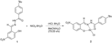
Initial work focussed on developing a method for determining the level of removal of Ni from solution. Previous studies have used chelating Schiff ligands to determine Ni2+ and Cd2+ concentrations in wastewater by use of UV-Vis spectroscopy.27,28 Taking inspiration from this work, we synthesised Schiff ligand 1 with a tBu group to improve solubility in organic solvents (Scheme 1). UV-Vis spectroscopy showed that a significant change in absorbance spectra occurs when 1 is reacted with NiCl2·6H2O. To enable a range of Ni sources to be detected, we developed an HPLC method that calculates the [Ni2+] based on the consumption of 1 (see ESI,† Section S5). HPLC measurements showed that 1 and Ni2+ bind quantitively, assuming formation of complex 2, up to a ratio of ∼0.7![[thin space (1/6-em)]](https://www.rsc.org/images/entities/char_2009.gif) :
:![[thin space (1/6-em)]](https://www.rsc.org/images/entities/char_2009.gif) 1 [Ni]/[1]. Above this, equilibration becomes relevant, and binding is no longer linear. As can be seen in Table 1, this method is accurate for quantifying [Ni] in solution provided that the ratio of [Ni]/[1] remains less than 0.7, and preferably in the region 0.1–0.6 to ensure linear binding. A range of data points using varying concentrations of 1 is also desirable, again to ensure that linear binding is occurring (and an average of the data points can be taken), but it is possible to get a reasonable estimation from just one data point (entries 6, 8).
1 [Ni]/[1]. Above this, equilibration becomes relevant, and binding is no longer linear. As can be seen in Table 1, this method is accurate for quantifying [Ni] in solution provided that the ratio of [Ni]/[1] remains less than 0.7, and preferably in the region 0.1–0.6 to ensure linear binding. A range of data points using varying concentrations of 1 is also desirable, again to ensure that linear binding is occurring (and an average of the data points can be taken), but it is possible to get a reasonable estimation from just one data point (entries 6, 8).
| Entry | Ni complex | Prepared [Ni]/mM | Calculated [Ni] (HPLC)/mM | [Ni]/[1] ratio range |
|---|---|---|---|---|
| a Mass of Ni complex weighed out independently (so initial [Ni] unknown at the point of calculation and determination). b Concentration determined from 1 data point. | ||||
| 1 | NiCl(o-tolyl)(PPh3)2a | 0.340 | 0.393 | 0.18–0.59 |
| 2 | NiCl(o-tolyl)(PPh3)2a | 0.605 | 0.618 | 0.15–0.55 |
| 3 | NiCl(o-tolyl)(PPh3)2a | 0.156 | 0.178 | 0.11–0.19 |
| 4 | NiCl(o-tolyl)(PPh3)2a | 0.422 | 0.421 | 0.14–0.46 |
| 5 | NiBr2(PPh3)2 | 0.348 | 0.343 | 0.12–0.37 |
| 6 | NiCl2·6H2Ob | 2.19 | 2.40 | 0.32 |
| 7 | NiCl2(dppp) | 0.587 | 0.589 | 0.12–0.50 |
| 8 | Ni(OAc)2·4H2Ob | 2.23 | 2.27 | 0.50 |
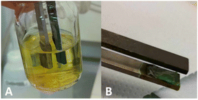
With this method of analysis in hand, we set out to electrochemically recover Ni from solutions of Ni2+. Initially, we deployed batch techniques using an Asynt ElectroReact® to standardise the method.29 The experimental setup used a graphite anode and a stainless steel (SS) cathode, where any reduced Ni should deposit. The two Ni sources tested were NiBr2(PPh3)23 and NiCl2(dppp) 4, both of which contain phosphine ligands. As the reduction of Ni2+ to Ni0 requires a concurrent oxidation process, it was envisaged that the 2-electron oxidation of phosphine ligand to phosphine oxide would provide an adequate balance. Cyclic voltammetry (CV) of 3 and 4 in MeCN showed an irreversible reduction at −0.946 V and −0.957 V, and oxidation at 0.795 V and 0.568 V respectively (relative to ferrocene) (see ESI† Section S7). As such, it was decided to use a constant potential difference rather than constant current during the electrochemical recovery process. Initially, K3PO4 was deployed as the electrolyte with the electrolysis of 3, as it is commonly used in cross-coupling reactions. However, in the MeCN/H2O solvent used, significant solubility issues resulted, and a potential difference of 4.0 V was required to achieve a suitable initial current (16 mA). After 16 h, a significant quantity of black particulate matter (assumed to be Ni colloids) was observed in the reaction mixture and coating the SS electrode. Analysis of the remaining solution by the HPLC method determined the electrochemical removal of 91% of Ni compared to the starting concentration (Table 2). Changing the electrolyte from K3PO4 to the more soluble PPh4Br allowed a lowering of the potential to 2.5 V (for 3), this time giving 80% electrochemical removal of Ni (HPLC method). In this case, the Ni was deposited as a green film on the SS electrode making removal much easier, and the solution turned yellow, likely due to Br2 formation (Fig. 1). The green deposits were examined using IR and FarIR spectroscopy, ion chromatography, silver halide test, ICP and pXRD analysis. The data indicate the presence of predominantly NiO. Changing the solvent mixture to 1,4-dioxane (also commonly used for SMCCs)30/H2O gave a lower level of recovery (27% at 3.3 V), but after 6 h the current had dropped to zero, possibly due to fouling on the electrode and an increased resistance.
| Conditions (electrolyte, solvent, P.D., time) | Initial [Ni]/mM | [Ni] after EC recovery (HPLC)/mM | [Ni] after EC recovery (ICP)/mM | % recovery of Ni (HPLC) | [Ni]/[1] ratio range |
|---|---|---|---|---|---|
K3PO4, MeCN/H2O (75![[thin space (1/6-em)]](https://www.rsc.org/images/entities/char_2009.gif) : :![[thin space (1/6-em)]](https://www.rsc.org/images/entities/char_2009.gif) 25 v/v), 4.0 V, 16 h 25 v/v), 4.0 V, 16 h |
17.11 | 1.59 | <LOQ | 91 | 0.22–0.52 |
PPh4Br, MeCN/H2O (75![[thin space (1/6-em)]](https://www.rsc.org/images/entities/char_2009.gif) : :![[thin space (1/6-em)]](https://www.rsc.org/images/entities/char_2009.gif) 25 v/v), 2.5 V, 16 h 25 v/v), 2.5 V, 16 h |
15.13 | 3.05 | 2.91 | 80 | 0.11–0.41 |
PPh4Br, 1,4-dioxane/H2O (75![[thin space (1/6-em)]](https://www.rsc.org/images/entities/char_2009.gif) : :![[thin space (1/6-em)]](https://www.rsc.org/images/entities/char_2009.gif) 25 v/v), 3.3 V, 6 h 25 v/v), 3.3 V, 6 h |
12.06 | 8.80 | 10.01 | 27 | 0.15–0.29 |
Throughout the studies, ICP was deployed as a “gold standard” to verify the results, which are broadly consistent with the HPLC method. There are variations between the two methods, most likely due to the very low concentrations of Ni being quantified.
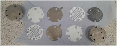
Buoyed by the success of the batch electrochemical recovery, it was decided to move to a flow system, using equipment developed by our group (Fig. 2).31,32 For electrochemical processes, flow offers advantages over batch in the large electrode surface area:volume ratio and a very small distance between the electrodes, allowing for efficient processes.33,34 A solution of 3 with PPh4Br electrolyte was pumped through the flow cell (2.0 V), and after 2 residence times, a fraction was collected and analysed by the HPLC method. To our delight, a removal level of 85% of Ni was achieved, and significant deposits of green Ni were observed on the SS cell electrodes (Fig. 3). Increasing the flow rate under the same conditions for the same sample expectedly reduced the removal level to 74% due to reduced residence time. Subsequent flow electrochemical recovery experiments used a compromise flow rate of 0.075 mL min−1, which for a solution of 4 removed 83% Ni, with total decolourisation of the solution from bright red, and the formation of red Ni deposits. A test involving 4 in 1,4-dioxane/H2O (at 2.3 V) showed a Ni removal of 58%, showing that the electrochemical process is solvent dependant (Table 3).
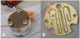 | ||
| Fig. 3 (A) Assembled electrochemical flow cell in operation; (B) SS electrode after electrochemical recovery of 3 in MeCN/H2O. | ||
| Ni complex, flow rate (mL min−1), residence time (min) | Initial [Ni]/mM | [Ni] after EC recovery (HPLC)/mM | [Ni] after EC recovery (ICP)/mM | % recovery (HPLC) |
|---|---|---|---|---|
| a 1,4-Dioxane/H2O solvent mixture. b SMCC reaction mixture A (Scheme 2) c SMCC reaction mixture B (Scheme 2). | ||||
| NiBr2(PPh3)2, 0.050, 18.56 | 20.85 | 3.19 | 1.69 | 85 |
| NiBr2(PPh3)2, 0.100, 9.28 | 20.85 | 5.48 | 5.01 | 74 |
| NiCl2(dppp), 0.075, 12.37 | 14.60 | 2.43 | 1.70 | 83 |
| NiCl2(dppp), 0.075, 12.37a | 15.18 | 6.33 | 7.72 | 58 |
| Reaction A, NiCl(o-tolyl)(PPh3)2, 0.075, 12.37b | 4.05 | 0.67 | 0.51 | 84 |
| Reaction B, NiCl2(dppp), 0.075, 12.37c | 17.7 | 4.78 | 5.02 | 73 |
The final test of the electrochemical recovery process involved the recovery of Ni from SMCC reaction mixtures. To this end, two SMCC reactions were performed (Scheme 2), one using NiCl(o-tolyl)(PPh3)25 in a reaction that was developed and optimised for flow,35 and the other was a modified literature SMCC using 4 in 1,4-dioxane.36 A high yielding (B) and a poorer yielding (A) reaction were chosen to reflect different levels and types of catalyst speciation during the reaction. For the reaction using 5, the solvent was first removed in vacuo, and the residue dissolved (with aid of sonication) in 75% MeCN/H2O. The presence of product 6 was determined by GC-HRMS and 19F NMR spectroscopy, and a sample analysed for [Ni] by the HPLC method. The rest of the reaction mixture was pumped through the electrochemical flow cell (2.0 V) and analysed by the HPLC method following electrochemical recovery. Unexpectedly, there was no change in the observed [Ni] before (0.66 mM) and after (0.67 mM) the electrochemical recovery process. However, ICP analysis revealed that while the HPLC correctly determined the [Ni] after recovery (0.67 mM), before recovery the actual [Ni] was 4.05 mM (equivalent to 18.2 mg of 5 in the reaction mixture, cf. 17.8 mg of 5 added for the reaction). This highlights one issue with Ni catalysed SMCCs; Ni aggregates exist, so direct analysis of the reaction mixture using chelating ligands (and by extension Ni scavengers for purification) may grossly underestimate [Ni]. However, electrochemistry not only removes Ni from solution, it also destroys Ni aggregates, allowing for chelation and hence accurate detection by the HPLC method. Improved chelation also significantly improves the chances of further metal removal through traditional techniques. Additionally, GC-HRMS and 19F NMR spectroscopy confirmed that the product 6 remained broadly unchanged by the electrochemical recovery process, but that triphenylphosphine oxide was formed, confirming that phosphine oxidation is a countering process at the anode.
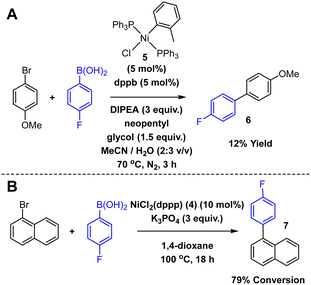 | ||
| Scheme 2 SMCC reactions.35,36 | ||
Flow electrochemical recovery of the second SMCC in 1,4-dioxane (catalysed by 4) resulted in a Ni removal of 73.0% (compared to initial 4 in the reaction mixture). Again, GC-HRMS and 19F NMR spectroscopy confirmed the presence of product 7 and demonstrated that it remained unchanged by the electrochemical recovery.
In summary, we have developed batch and flow-electrochemical recovery protocols for the removal of Ni from catalytic reaction solutions. A low cost, widely applicable and accurate method for detecting trace Ni using chelating ligands and HPLC has enabled the remaining [Ni] following electrolysis to be quantified. This methodology has been verified by the gold standard of ICP analysis. We have shown that for two relevant Ni-catalysed SMCCs, the transition metal is removed by chemical deposition on the electrodes, and the chemical product is unchanged by electrochemical recovery. As part of this, we have determined that electrochemical metal recovery is able to break down Ni aggregates into one monomeric form, allowing for accurate quantification by the HPLC method. This exploratory work prepares the way for applications of significance to industrial processing. Predominantly, we envisage flow electrochemical recovery of transition metal catalysts as a routine step in the preliminary purification of APIs, enabling high catalyst concentrations for challenging transformations and for toxic heavy metals to be recovered much more efficiently and cheaply than current scavenging methods. We speculate that this method will be compatible with other precious metal catalysts such as Pd and Pt, as the Schiff ligand 1 has potential to coordinate other metal centres, warranting further investigation. The longevity of the electrochemical flow reactors and electrode material will require consideration, as electrode fouling may compromise current stability. Finally, we propose that flow electrochemical recovery could be relevant in closed loop systems, where the transition metal catalyst is both synthesised and recovered/reused locally in flow by electrochemical methods.31,37 This will also enable regeneration and reuse of the electrodes and improve reactor longevity.
The University of York are acknowledged for IAA funding. The authors wish to thank Karl Heaton (mass spectrometry), Dr Richard Gammons and Dr Adrian Whitwood (X-ray crystallography), Dr Scott Hicks and Dr Chris Horbaczewskyj for their help with LC method development, and Prof. Ian Fairlamb for useful discussions.
Data availability
The data for this manuscript can be found at https://doi.org/10.15124/fb6309f5-af8c-4690-be8e-8eb67238777d. This includes raw NMR (FIDs), ICP and UVvis data and LC processing spreadsheets.Conflicts of interest
There are no conflicts to declare.Notes and references
- J. D. Hayler, D. K. Leahy and E. M. Simmons, Organometallics, 2019, 38, 36–46 CrossRef CAS.
- J. Malinowski, D. Zych, D. Jacewicz, B. Gawdzik and J. Drzeżdżon, Int. J. Mol. Sci., 2020, 21, 5443 CrossRef CAS PubMed.
- C. A. Busacca, D. R. Fandrick, J. J. Song and C. H. Senanayake, Adv. Synth. Catal., 2011, 353, 1825–1864 CrossRef CAS.
- A. Rajeev, M. Balamurugan and M. Sankaralingam, ACS Catal., 2022, 12, 9953–9982 CrossRef CAS.
- L. J. Taylor and D. L. Kays, Dalton Trans., 2019, 48, 12365–12381 RSC.
- J. Rana, S. T. Sahoo and P. Daw, Tetrahedron, 2021, 99, 132473 CrossRef CAS.
- ICH Guideline Q3D (R2) on Elemental Impurities, European Medicines Agency, 2022.
- J. García-Serna, R. Piñero-Hernanz and D. Durán-Martín, Catal. Today, 2022, 387, 237–243 CrossRef.
- S. Goel, K. K. Pant and K. D. P. Nigam, J. Hazard. Mater., 2009, 171, 253–261 CrossRef CAS PubMed.
- B. Qu, X. Wei, X. Zeng, B.-S. Yang, J.-N. Desrosiers, J. Savoie, J. Wang, M. A. Marsini, Z. Li, N. Haddad, J. C. Lorenz, P. Tielmann, N. Maier, J. J. Song and C. H. Senanayake, Org. Process Res. Dev., 2022, 26, 963–975 CrossRef CAS.
- I. R. Baxendale, S. V. Ley, A. C. Mansfield and C. D. Smith, Angew. Chem., Int. Ed., 2009, 48, 4017–4021 CrossRef CAS PubMed.
- M. Fuchs, W. Goessler, C. Pilger and C. O. Kappe, Adv. Synth. Catal., 2010, 352, 323–328 CrossRef CAS.
- J. Li, D. Smith, S. Krishnananthan and A. Mathur, Org. Process Res. Dev., 2020, 24, 454–458 CrossRef CAS.
- M. Mohadjer Beromi, A. Nova, D. Balcells, A. M. Brasacchio, G. W. Brudvig, L. M. Guard, N. Hazari and D. J. Vinyard, J. Am. Chem. Soc., 2017, 139, 922–936 CrossRef CAS PubMed.
- D. B. Eremin and V. P. Ananikov, Coord. Chem. Rev., 2017, 346, 2–19 CrossRef CAS.
- L. N. Lewis, Chem. Rev., 1993, 93, 2693–2730 CrossRef CAS.
- M. Economidou, N. Mistry, K. M. P. Wheelhouse and D. M. Lindsay, Org. Process Res. Dev., 2023, 27, 1585–1615 CrossRef CAS.
- J. Jo, Q. Tu, R. Xiang, G. Li, L. Zou, K. M. Maloney, H. Ren, J. A. Newman, X. Gong and X. Bu, Organometallics, 2019, 38, 185–193 CrossRef CAS.
- V. Balaram, TrAC, Trends Anal. Chem., 2016, 80, 83–95 CrossRef CAS.
- L. Yang, W. Hu, Z. Chang, T. Liu, D. Fang, P. Shao, H. Shi and X. Luo, Environ. Int., 2021, 152, 106512 CrossRef CAS PubMed.
- W. Jin and Y. Zhang, ACS Sustainable Chem. Eng., 2020, 8, 4693–4707 CrossRef CAS.
- W. Jin, P. I. Laforest, A. Luyima, W. Read, L. Navarro and M. S. Moats, RSC Adv., 2015, 5, 50372–50378 RSC.
- M. J. West and A. J. B. Watson, Org. Biomol. Chem., 2019, 17, 5055–5059 RSC.
- S. Z. Tasker, E. A. Standley and T. F. Jamison, Nature, 2014, 509, 299–309 CrossRef CAS PubMed.
- K. S. Kasprzak, F. W. Sunderman and K. Salnikow, Mutat. Res., 2003, 533, 67–97 CrossRef CAS PubMed.
- E. Denkhaus and K. Salnikow, Crit. Rev. Oncol. Hematol., 2002, 42, 35–56 CrossRef CAS PubMed.
- B. N. Kumar, S. Kanchi, M. I. Sabela, K. Bisetty and N. V. V. Jyothi, Karbala Int. J. Mod. Sci., 2016, 2, 239–250 CrossRef.
- B. N. Kumar, S. H. Kumar, G. G. Redhi and N. V. V. Jyothi, Asian J. Chem., 2016, 28, 1861–1866 CrossRef CAS.
- H. R. Stephen, C. Schotten, T. P. Nicholls, M. Woodward, R. A. Bourne, N. Kapur and C. E. Willans, Org. Process Res. Dev., 2020, 24, 1084–1089 CrossRef CAS.
- A. Jordan, C. G. J. Hall, L. R. Thorp and H. F. Sneddon, Chem. Rev., 2022, 122, 6749–6794 CrossRef CAS PubMed.
- C. Schotten, J. Manson, T. W. Chamberlain, R. A. Bourne, B. N. Nguyen, N. Kapur and C. E. Willans, Catal. Sci. Technol., 2022, 12, 4266–4272 RSC.
- T. P. Nicholls, R. A. Bourne, B. N. Nguyen, N. Kapur and C. E. Willans, Inorg. Chem., 2021, 60, 6976–6980 CrossRef CAS PubMed.
- C. Schotten, T. P. Nicholls, R. A. Bourne, N. Kapur, B. N. Nguyen and C. E. Willans, Green Chem., 2020, 22, 3358–3375 RSC.
- T. P. Nicholls, C. Schotten and C. E. Willans, Curr. Opin. Green Sustainable Chem., 2020, 26, 100355 CrossRef.
- X. Guo, H. Dang, S. R. Wisniewski and E. M. Simmons, Organometallics, 2022, 41, 1269–1274 CrossRef CAS.
- Y.-L. Zhao, Y. Li, S.-M. Li, Y.-G. Zhou, F.-Y. Sun, L.-X. Gao and F.-S. Han, Adv. Synth. Catal., 2011, 353, 1543–1550 CrossRef CAS.
- M. R. Chapman, S. E. Henkelis, N. Kapur, B. N. Nguyen and C. E. Willans, ChemistryOpen, 2016, 5, 351–356 CrossRef CAS PubMed.
Footnote |
| † Electronic supplementary information (ESI) available. CCDC 2351245. For ESI and crystallographic data in CIF or other electronic format see DOI: https://doi.org/10.1039/d4cc02000f |
| This journal is © The Royal Society of Chemistry 2024 |

