
 Open Access Article
 This Open Access Article is licensed under a
 Creative Commons Attribution 3.0 Unported Licence
Potential energy interpolation with target-customized weighting coordinates: application to excited-state dynamics of photoactive yellow protein chromophore in water†
Seung Soo
Kim
 and
Young Min
Rhee
*
and
Young Min
Rhee
*
Department of Chemistry, Korea Advanced Institute of Science and Technology (KAIST), Daejeon 34141, Korea. E-mail: ymrhee@kaist.ac.kr
First published on 20th February 2024
Abstract
Interpolation of potential energy surfaces (PESs) can provide a practical route to performing molecular dynamics simulations with a reliability matching a high-level quantum chemical calculation. An obstacle to its widespread use is perhaps the lack of general and optimal interpolation settings that can be applied in a black-box manner for any given molecular system. How to set up the weights for interpolation is one such task, and we still need to diversify the approaches in order to treat various systems. Here, we develop a new interpolation weighting scheme, which allows us to choose the weighting coordinates in a system-specific manner, by amplifying the contribution from specific internal coordinates. The new weighting scheme with an appropriate selection of coordinates is proved to be effective in reducing the interpolation error along the reaction pathway. As a demonstration, we consider the photoactive yellow protein chromophore system, as it constitutes itself as an interesting target that bears long-standing questions related to excited-state dynamics inside protein environments. We build its two-state diabatic interpolated PES with the new weighting scheme. We indeed see the utility of our scheme by conducting nonadiabatic molecular dynamics simulations with the required semi-global PES based on a limited number of data points.
1. Introduction
Nonadiabatic molecular dynamics (NAMD) simulation has become one of the crucial tools to investigate photo-induced processes in diverse chemical systems. Together with the continuing efforts in theoretical developments1–5 and recently achieved code implementations,6–15 performing NAMD simulations for molecules in complex environments has now become more of a routine task than ever before. The task always calls for the use of a multistate potential energy surface (PES), and in the majority of simulation efforts, PES information has been obtained in a direct manner with on-the-fly evaluations of electronic structures practically at each and every conformation visited during the simulations. Thus, the associated computational cost often hampers the application of NAMD. For the same reason, when the simulations are conducted for a condensed phase, statistical reliability becomes inevitably limited even after employing cost-saving multiscale approaches such as the hybrid quantum mechanics/molecular mechanics (QM/MM) method.16,17To reduce the computational cost associated with the direct evaluation of PES information, tactics of modeling PESs have been widely pursued through various fitting,18–22 interpolation,23–25 and machine-learning techniques.26–32 Among these, the PES models based on modified Shepard's interpolation (MSI)23,33–43 have been known for their data-driven features and formal simplicity. MSI approximates the semi-global PES as a weighted average of the Taylor expansions around all data points. Although the original model was proposed for gas-phase reactive dynamics,23,33,34 the scheme was continually extended to cover a wide variety of situations.44–57 The extensions include the interpolation of multiple and coupled electronic states for addressing excited-state dynamics simulations,46–49 and the linking with molecular mechanics (MM) potentials to efficiently model environmental effects in condensed-phase dynamics.51–53,56 The interpolation mechanics/molecular mechanics (IM/MM)54,58 approach and the electrostatically embedded multiconfigurational molecular mechanics/molecular mechanics50–52 can be considered as two examples with such extensions. In recent applications, such approaches were successfully employed to simulate the excited-state intramolecular proton transfer of a dye molecule in solution,59 nonadiabatic dynamics of fluorescent proteins,60 and excited-state dynamics of light-harvesting complexes.61–63 Thus, together with the recently booming machine-learning approaches,64–67 the MSI technique provides a potential framework for efficiently constructing PESs for condensed-phase molecular dynamics simulations. However, as in other data-driven approaches, the method is still challenged by two major aspects: (1) building a reliable dataset along a targeted reaction pathway, and (2) finding the optimal interpolation form for a given dataset. In this study, we will concentrate on the latter of these two challenges.
One of the key issues that determine the overall quality of MSI is the choice of the interpolating weight function.39,42 Usually, a weight is assigned to each data point and is chosen to be inversely proportional to the geometric distance from the data point. Thus, the primary concern in choosing the weight function is the definition of the weighting coordinates, whose differences for a pair of conformations are translated into the distance between the conformations. In fact, the choice of the weighting coordinates had been the focus of some early methodological studies.36,37,39,41 While internal weighting coordinates can be more directly related to the molecular force constant, as in conventional MM force fields, Cartesian weighting coordinates give a more uniformly distributed dataset points in space. A previous study showed that this uniformity can be important for faster convergence of PES construction, especially for planar systems.41 However, properly choosing weighting coordinates is essentially a chemistry problem and is related to the intrinsic character of the targeted system such as its reaction coordinates and molecular geometry. Indeed, a small geometric distortion in some molecules may induce a large change in their potential and derivatives, while in others, even a large distortion only generates a minor change. For instance, in the case of retinal chromophores in bovine rhodopsin,68,69 which has been repeatedly studied as a model system for photosensory proteins, the hydrogen out-of-plane (HOOP) coordinate has been pointed out as a critical mode during its ultrafast photoisomerization reaction.70,71 From a purely geometric perspective, the HOOP motion does not produce a large displacement and is therefore “insignificant” compared to the isomerization coordinate. However, multiple studies have suggested that the HOOP coordinate is important in controlling the orbital overlap between the conjugated π-fragments and that its velocity component strongly affects the direction of isomerization especially in the vicinity of its transition state.70,72,73 Moreover, studies that targeted biological chromophores in other photosensory proteins also reported similar observations regarding similarly defined coordinates.74,75 Therefore, when one models such chromophores with MSI, one will need to assign the interpolation weights such that special care is provided to the HOOP coordinate. More generally, it becomes necessary to work in a system-specific way toward assigning the weighting coordinates. The aim of this work is to try out such a framework on top of the conventional MSI method with an eventual purpose of establishing a generalized strategy.
Accordingly, in this work, we present a new weighting scheme to improve the quality of interpolated PESs. We apply the new scheme to construct a coupled diabatic PES model of the thioester derivative of p-coumaric acid in photoactive yellow protein (PYP).76,77 In the new scheme, the weighting coordinates are divided into two groups: conventional Cartesian weighting coordinates and additional internal one(s) that are intuitively chosen from a chemical sense in a system-specific way. In general, we expect one or two such coordinates will likely be enough in most cases and pick one for p-coumaric acid. By applying the scheme to this PYP chromophore, we show that the mixed and redundant weighting coordinates actually improve the overall quality of MSI, proving that the new weighting scheme provides more accurate yet simple enough formal framework for future applications of the MSI technique. With the constructed diabatic PES, we simulate nonadiabatic surface hopping dynamics of the PYP chromophore in an aqueous solution, and show that dynamic electron correlations are important for reliably simulating excited-state dynamics of the chromophore, which will likely be the case for other organic chromophores.78–80
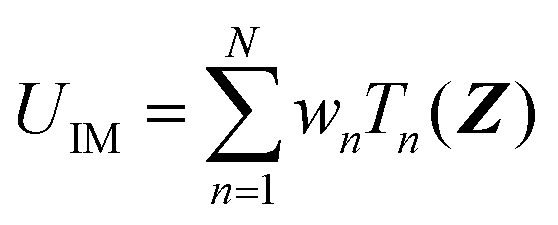
2. Theory
2.1. IM/MM model
Analogous to the additive scheme in the hybrid QM/MM model,17 the total IM/MM energy UIM/MM can be written as| UIM/MM = UIM + UMM + UIM–MM + Ustab | (1) |
 | (2) |
 | (3) |
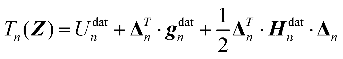
Finally, the displacement vector Δn from the nth data point geometry Zndat to the current geometry Z is defined as
 | (4) |
2.2. Interpolation weight function
As mentioned in the introduction, how to define the interpolation weight function is one of the key factors of IM/MM, which determines the overall quality of the interpolated PES. Usually, the weight function wn is normalized from an unnormalized weight υnvia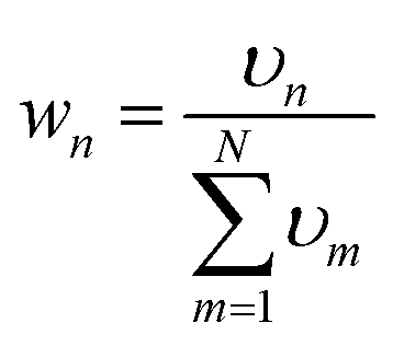 | (5) |
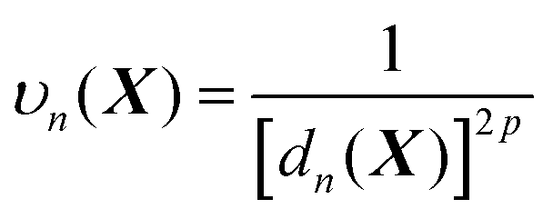 | (6) |
In line with the previous report,53 we choose p = 6 for all one-part weight functions used in this study. Additionally, a little more sophisticated case involves a two-part weight function:37,57
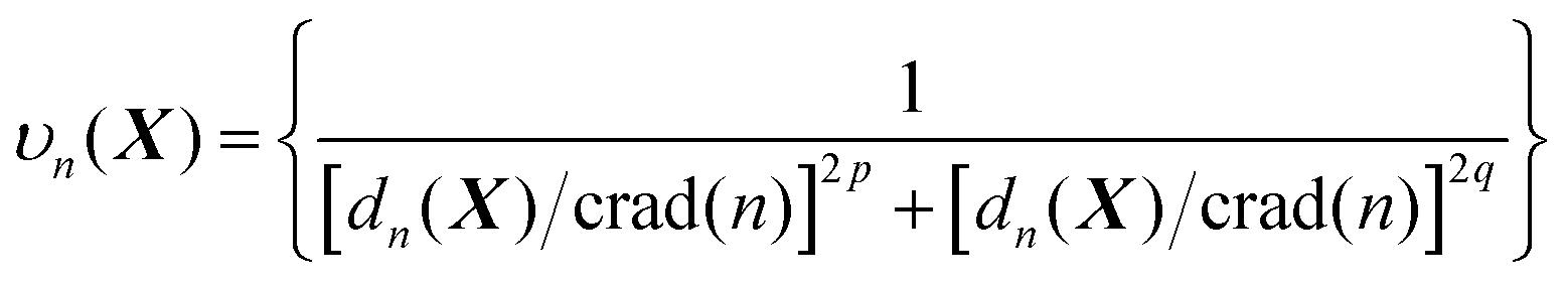 | (7) |
2.3. Target-customized weighting coordinates
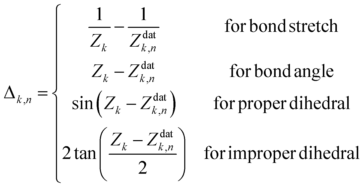
We now turn to the main point of this work. As mentioned in the Introduction, adding customized weighting coordinate(s) that are chosen intuitively can improve the quality of interpolation as it can provide weights in a more system-specific manner. In this case, in the most general form, the modified distance between the current geometry and the nth data point can be written as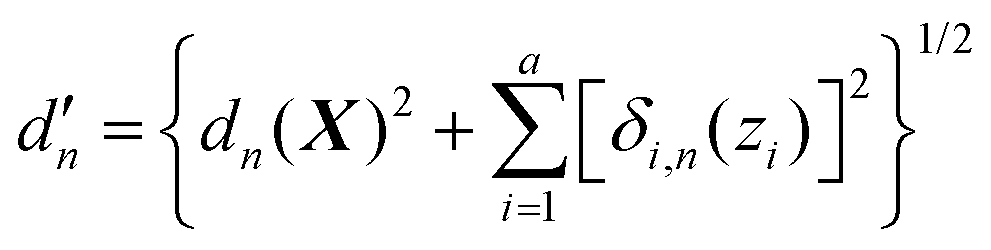 | (8) |
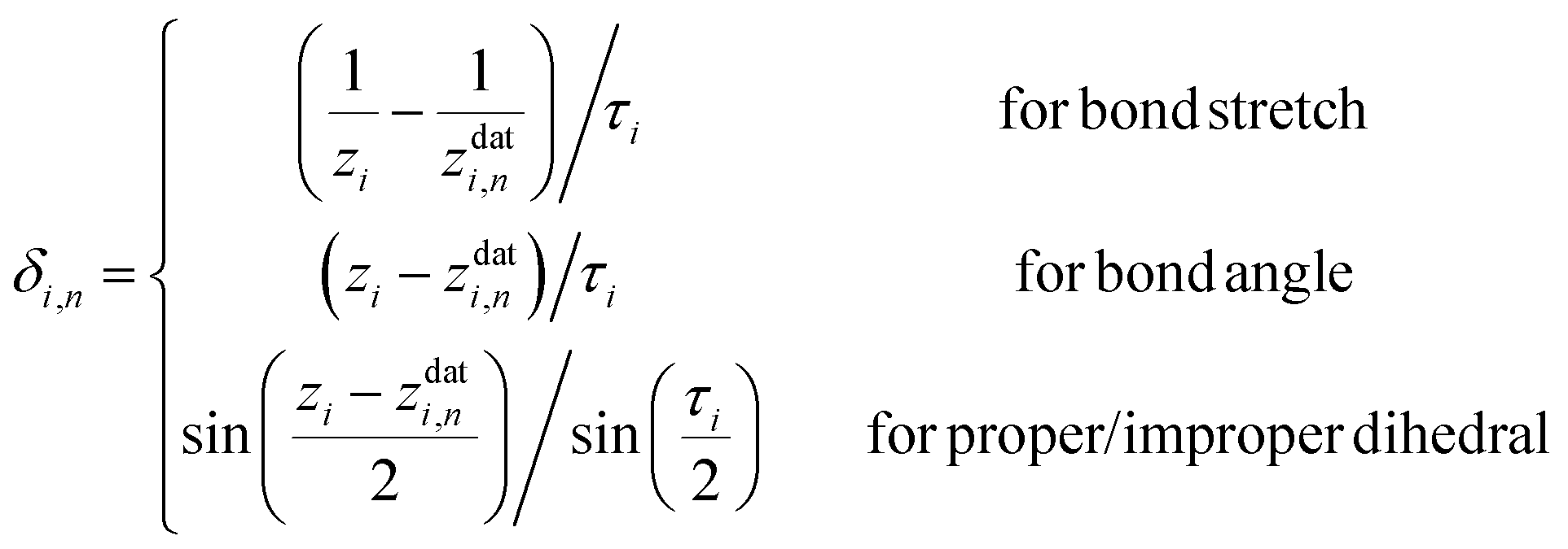
Here, a is the number of such customized weighting coordinates, and δi,n(zi) is the effective distance with respect to the ith customized weighting coordinate, zi. One should note that this modified distance depends on both the Cartesian and internal coordinates of the current geometry. Of course, the Cartesian and the internal coordinates will be correlated in some way, but this correlation does not cause any mathematical trouble as long as the modified distance is a positive-definite function around the data point. We also note that the weighting distance with redundant coordinates has been successfully adopted in earlier reports.37,39 The definition of the effective distance is straightforward, and similar to eqn (4), it can be defined as
 | (9) |
In general, there is no limit on how many customized weighting coordinates can be used, and the number a should be selected to well represent the chemistry of the system of interest. In many situations, interesting dynamics rather follow a low dimensional space (e.g., reaction along a minimum energy path), and we expect that a single additional weighting coordinate may work well enough in many cases. In this case with a = 1, in combination with the simple form of the weight function (eqn (6)), the unnormalized weight can be written as
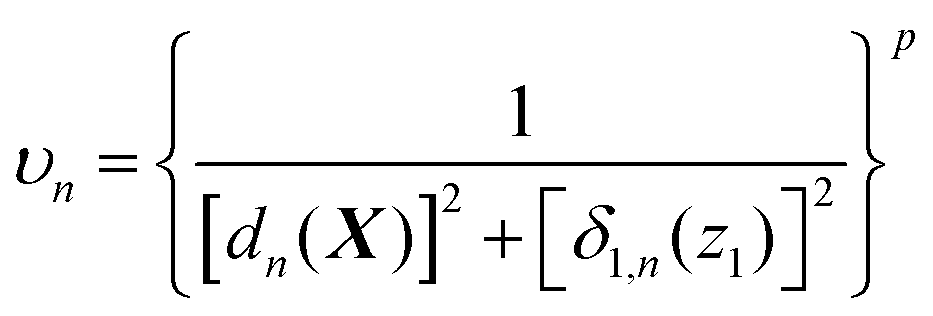 | (10) |
Using the two-part weighting function (eqn (7)) is also possible, and we will indeed use it in analyzing the detailed effects of adopting the customized weighting coordinate in results and discussion. Throughout these analyses, the errors of the Taylor expansions from the data points that mainly participated the IM energy (eqn (2)) need to be monitored. Toward this end, the inverse participation ratio (IPR)35 can be adopted, which is defined as
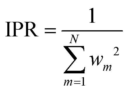 | (11) |
By definition, the IPR value converges to unity as the running geometry coincides with one of the data point geometries, while it reaches N as the distances from all data points becomes divergently large. Therefore, IPR represents the effective number of main contributors in a weighted average shown in eqn (2).
3. Computational details
3.1. Electronic structure calculations
All electronic structure calculations were conducted with the MOLPRO software package (version 2010.1).83 To handle both the ground and the excited states, state-averaged complete active-space self-consistent field (SA-CASSCF)84,85 and multistate complete active-space second-order perturbation theory (MS-CASPT2)86 calculations with the 6-31G* basis set87–90 were employed, with equal weights on the two states in SA-CASSCF. To build the IM database, the SA-CASSCF energies, analytical gradients, and nonadiabatic coupling vectors were calculated. Also, the second order derivatives (not only Hessians but the gradients of nonadiabatic coupling vectors) were computed numerically as the central difference of the related first order derivatives.For MS-CASPT2 calculations, 32 upper SA-CASSCF orbitals were explicitly correlated following the standard implementation of MOLPRO. A level shift of 0.2 a.u. was employed to facilitate the convergence of MS-CASPT2. Similar to the SA-CASSCF case, the MS-CASPT2 energies and their analytical gradients were computed for all data points but neither second order derivatives nor nonadiabatic coupling vectors were calculated. Instead, the recently proposed α-CASSCF method91 was introduced to practically address the dynamic correlation in a more efficient way. In α-CASSCF, the SA-CASSCF energies are scaled with a single empirical parameter α. This parameter is set to minimize the RMS error between the relative α-CASSCF energy and the relative MS-CASPT2 energy at a few critical geometries. Following the earlier fitting procedures,91 the empirical parameter was determined to be 0.7 for the PYP chromophore. Thus, all the energies and derivatives obtained within the SA-CASSCF were rescaled with this empirical parameter to give the approximate second order Taylor's expansions for interpolated PES at the MS-CASPT2 level, and then the MS-CASPT2 energies and gradients were used to give the first order correction term to the approximate expansions. This approach can be regarded as the diabatic variant of the dual-interpolation scheme.33 The detailed explanation of this approach can also be found in the previous report.55
3.2. Details of IM/MM PESs
The Z-matrix internal coordinates used in the interpolation are listed in Table S1 (ESI†). We should note that the choice of bond angles and improper dihedrals is particularly important in avoiding unphysical non-planar geometries during the MD simulations with IM/MM. Before constructing the interpolation database, the MM stabilizer function for the PYP chromophore needs to be defined. Following earlier works,55,60 all bond stretching and bond angle bending modes in the chromophore were considered for this. All the parameters were obtained from the AMBER99SB force field.92 Specifically, the bond atom types in AMBER99SB were assigned for the atoms in the chromophore with a few missing parameters adjusted from similar bond stretching or bond angle terms. The scaling factor for the stabilizer was set to 0.02, also in accordance with earlier studies.53,60 Because the stabilizer only works as a bounding potential that prevents excessive bond stretching or angle bending, its exact form does not really matter for the simulation results when it is properly formed. The bond atom types used for the MM stabilizer are listed in ESI† with Fig. S2. We note that we additionally attached a stronger stabilizer potential with a scaling factor of 1.0 for one of the bond stretching modes on the phenoxy ring. That one bond was not included in the set of the Z-matrix internal coordinates in Table S1 (ESI†), and the purpose of this addition was to prevent spurious stretching along the bond.62To utilize an interpolated PES in studying condensed-phase nonadiabatic dynamics, one needs to handle state-dependent electrostatic interactions involving the chromophore. This can be achieved with diabatic atomic partial charges.56 In this work, we adopted the restricted electrostatic potential (RESP) fitting approach93 in a state-specific manner as follows. First, the geometry was optimized at the MS-CASPT2 level in the S0 ground state. At the optimized geometry, RESP fitting was processed for all SA-CASSCF one-particle reduced densities as well as the transition densities to generate a set of reference diabatic atomic partial charges as listed in Table S2 (ESI†). The sizes of the diabatic partial charges are insensitive to geometric changes, and the calculated RESP charges were kept fixed at all geometries toward calculating the electrostatic interactions between the IM and MM regions. Following earlier works,56,60 the Lennard-Jones interactions between the two regions were assumed to be state-independent after adjusting the Lennard-Jones parameters for the PYP chromophore simply by referring to the generalized amber force fields (GAFF).94
3.3. MD simulation protocol
To demonstrate the applicability of the interpolated PES, a series of excited-state MD simulations for the PYP chromophore in an aqueous solution were performed. All the MD simulations were performed with GROMACS 4.0.795 interfaced with home-made libraries for IM/MM. Before simulations, the anionic PYP chromophores were solvated in a cubic box with the side length of 50 Å, containing 4086 TIP3P water molecules and a single Na+ ion. The periodic boundary conditions were employed. For the long-range electrostatics and Lennard-Jones interactions, the cutoffs of 12 Å with the tapers of 10 Å were used to smoothly vary the associated forces. At first, the system was energy-minimized and equilibrated within the pure MM model. At this preliminary stage, the adjusted GAFF parameters for the PYP chromophore were used. Among the GAFF parameters, three torsional angle parameters related to the twisting motion around the conjugated C–C bond were adjusted to reproduce the potential energy curves obtained at the MS-CASPT2/6-31G* level. Also, the rotation of the thioester methyl group is restricted through a strong restraining potential. The whole system was energy-minimized with the steepest descent algorithm and then it was subsequently equilibrated under NpT conditions at 1 atm and 300 K. The integration time step for this MM equilibration trajectory was 2.0 fs with LINCS constraints96 on bonds involving hydrogen atoms. This trajectory was initially propagated for 0.5 ns using Berendsen's thermostat and barostat97 with the coupling time constants of 0.4 ps and 2.0 ps, respectively. After this, another equilibration trajectory was propagated for an additional 30 ns using the Nose–Hoover thermostat98 and the Parrinello–Rahman barostat99 with the same coupling time constants on both. After this, 400 independent equilibrated geometries were sampled from the final 20 ns window, with a time interval of 50 ps. These geometries were used as the starting configurations for the production IM/MM MD simulations.During the course of IM/MM MD simulations, the integration time step was 0.5 fs and no LINCS constraints were used. After switching to the IM/MM potential, each starting configuration was relaxed in the ground state for 20 ps, and the relaxed configurations thus obtained were used in the subsequent excited-state IM/MM NAMD simulations. Physically, this tactic corresponds to simulating the condition right after the Franck–Condon transition of the equilibrium ensemble. At time zero, the trajectory started in the S1 state and was propagated for 4.0 ps with an integration time step of 0.5 fs.
3.4. Surface hopping algorithm
The nonadiabatic transitions were treated with the Landau–Zenner type surface hopping (LZSH) algorithm56,60,100 as it can allow a longer time step than the more conventional fewest switch surface hopping (FSSH) algorithm1 or its variants. With LZSH, the transition probability was calculated at every step following: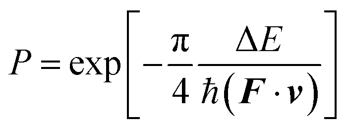 | (12) |
4. Results and discussion
4.1. Definition of the diabatic states
As alluded in an earlier part, when we interpolate coupled electronic states, appropriately representing (quasi-)diabatic states is essential for dealing with the sudden change in IM/MM potentials near surface crossing.49 Before moving on to the explanations of more dynamical aspects, let us first examine the charge-localized diabatic states of the PYP chromophore, obtained with SA-CASSCF. The chemical structure of the chromophore together with the definitions of key internal coordinates is presented in Fig. 1. Apparently, the chromophore has three π-conjugated C–C bonds. The torsional coordinates centered at two of the π-conjugated C–C bonds are well-known as the twisting decay channel in the excited state.71,77 The first one is related to the rotation of the phenoxy moiety, while the second one pertains to the cis–trans isomerization of the chromophore. We will denote these two as α and β, respectively (Fig. 1). Also, quantum chemical calculations show that the HOOP motion in the vicinity of the β coordinate has a significant role in determining the excited-state decay channel. This HOOP coordinate can be defined based on the difference in the two torsional coordinates sharing the same π-conjugated C–C bond as a center (Fig. 1).75 As explained already, the torsional coordinate related to this HOOP can be set to have a deterministic role in interpolation weighting. This issue will be addressed in a later section.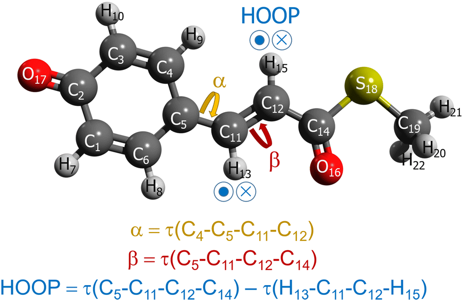 | ||
| Fig. 1 Chemical structure of the PYP chromophore with the definitions of the key internal coordinates, with τ(A–B–C–D) denoting the torsional angle involving the atoms A, B, C, and D. | ||
In the SA-CASSCF calculations, three orbitals with four electrons were selected for the active space. In fact, this choice has been proven to be useful in effectively modeling the charge-transfer diabatic states of monomethine dyes such as the anionic green fluorescent protein chromophore.101 Although the PYP chromophore does not belong to the group of monomethine dyes, we observed that the same choice was still valid for describing its charge transfer along α and β. Indeed, when we plot the active orbitals after Boys localization,102 we can clearly see that each one is well localized within the three well-distinguished fragments of phenoxy, bridge, and tail moieties (Fig. 2a). Furthermore, these localized active orbitals remain isomorphic in different geometries, and this isomorphism is particularly useful in defining the charge-localized diabatic states. Following the block-diagonalization formalism,103 the S0 and the S1 states can be transformed into two charge-localized diabatic states, which we name here as P- and Q-states, respectively. As the names suggest, the chemical properties of these diabatic states closely resemble the phenolic and quinonic resonance structures.104 The predominant electronic configuration in each charge-localized diabatic state is depicted in Fig. 2b. We also note that the similarly charge-localized diabatic states were defined for describing the charge transfer dynamics in monomethine dyes.101,105
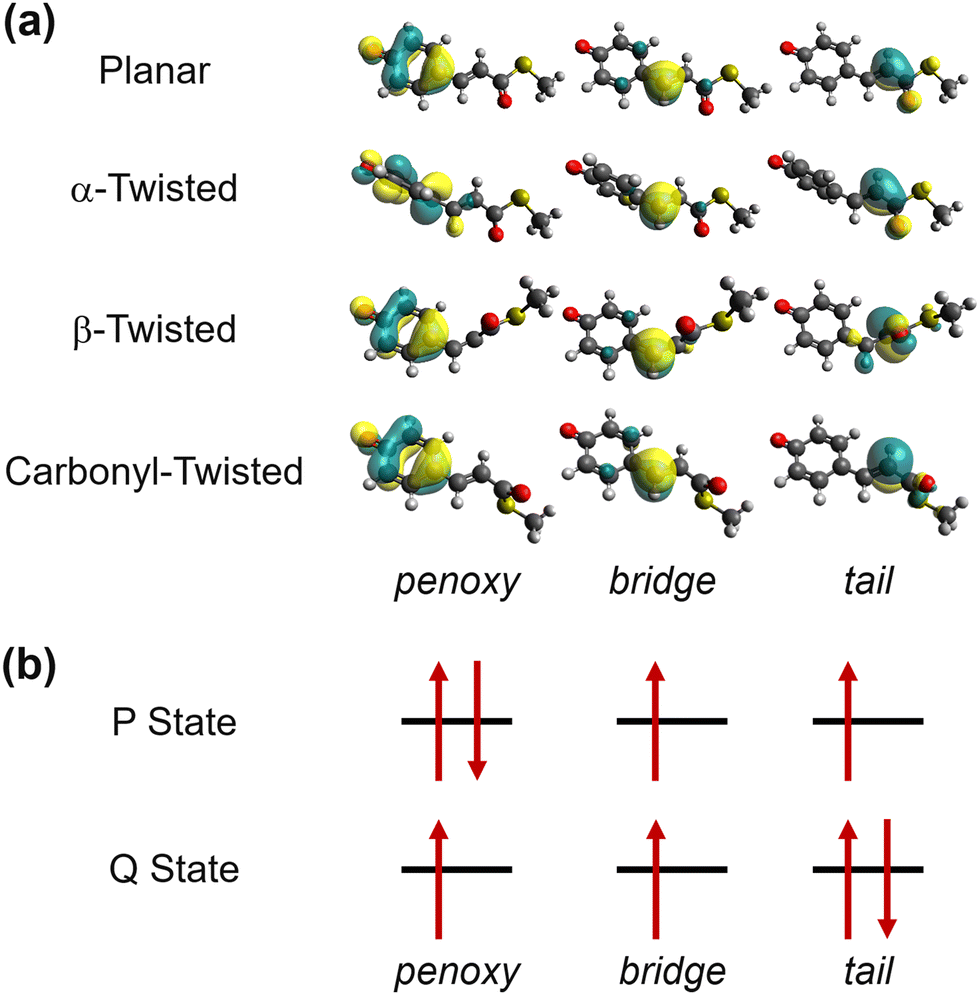 | ||
| Fig. 2 Electronic structure of the PYP chromophore. (a) Boys-localized active space orbitals in representative geometries, obtained from SA2-CAS(4,3)SCF calculations. The orbitals remain isomorphic in planar, α-twisted, β-twisted, and carbonyl-twisted geometries. The definitions of the α and the β torsions can be found in Fig. 1. (b) The predominant electronic configurations in diabatic states with the Boys-localized active orbitals. | ||
The resulting diabatic potential energy curves along α and β are depicted in Fig. 3a. In the planar geometry, the two diabatic states have similar energies with a large diabatic coupling (∼2.0 eV). As the geometry twists along either α or β, each diabatic state converges into one of the adiabatic states, meaning that S0 and S1 charges localize in different patterns. In other words, charge transfer occurs along with the change in α or β torsion. Particularly, S1 becomes the Q state in the α-twisted geometry, while it becomes P in the β-twisted geometry. Of course, these charge-localization patterns are consistent with what was reported in an earlier quantum chemical study.104
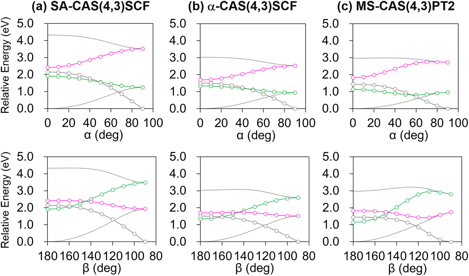 | ||
| Fig. 3 Diabatic potential energy curves along α and β, obtained with (a) SA-CASSCF, (b) α-CASSCF, and (c) MS-CASPT2 levels of theories. The green/magenta lines depict the P/Q state energies, whereas the gray lines represent the coupling between the two states. The two adiabatic potential energies are also shown in dotted lines. | ||
Although SA-CASSCF may provide a correct description of the electron configuration associated with the charge transfer and π-bond breaking, its deficiency in dynamic correlation remains a problem. This is mainly important concerning reaction barriers corresponding to bond breaking. In the case of the PYP chromophore, an early analysis showed that the isomerization reaction barrier in S1 is largely affected by the inclusion of dynamic correlation.106 Of course, a natural remedy will be to adopt perturbative correction to recover the missing correlation, and we of course applied it in this study. However, using it every time we collect a data point for interpolation was deemed to be excessively costly especially in terms of database construction. Therefore, we combined it with the recently proposed α-CASSCF, an empirical correction to SA-CASSCF with a single parameter to closely mimic MS-CASPT2 results.91 The diabatic potential energy curves based on α-CASSCF and MS-CASPT2 are shown in Fig. 3b and c, and we can notice that the α-CASSCF diabatic potential energy curves indeed closely mimic the MS-CASPT2 ones, although α-CASSCF was originally developed with regard to adiabatic energies. We reason that at least for the PYP chromophore case the predominant electron configurations of the two diabatic states remain the same in both α-CASSCF and MS-CASPT2 and thus their adiabatic-to-diabatic transformation matrices will be very close to each other, resulting also in a good agreement in the diabatic picture. Of course, there are some discrepancies between α-CASSCF and MS-CASPT2, especially on the energy barrier related to β-twisting (Fig. 3b and c). How this discrepancy can possibly affect the excited-state MD simulations will be discussed in Section 4.4.
Finally, it is worth mentioning that a similar tendency was also found for the diabatic potential energy curves along the HOOP coordinate (Fig. S3, ESI†) with the Boys-localized active space orbitals remaining isomorphic even with HOOP-twisting (Fig. S4, ESI†). Thus, the current diabatization procedure appears to be robust at least for the changes in the three important internal coordinates denoted in Fig. 1.
4.2. Construction of the interpolation database
With the charge-localized diabatic states explained above, the MS-CASPT2 level interpolation database was prepared by running a series of sampling MD simulations. Basically, our sampling relied on the “GROW scheme”,42,54,57 where the database was constructed iteratively with sampled data points from MD simulations.42 In this work, however, we adopted a somewhat different approach than before by dividing the whole database into independent bins, with an expectation that it will enhance the speed of database convergence especially because multiple points may be added in a parallel manner and because even a new bin can be dynamically added when necessary.The sampling conditions in all bins are summarized in Table 1. As shown in this table, the bins were distinguished with (i) the adiabatic electronic state for sampling simulations, (ii) the initial geometry of sampling simulations, and (iii) whether a restraining potential was used for sampling to prioritize a specific region in the conformational space. The first bin was filled up by simulating in S0 toward sampling well in the vicinity of the Frank-Condon region. Of course, in this sampling, the trajectory was initiated from the S0-optimized geometry and no restraining potential was applied. Next, samplings were conducted on the S1 state to cover the α/β twisting pathways. Because there are four S1 state minima with clockwise and anti-clockwise twisting on both α and β, data points in their vicinities were sampled through four independent bins. Samplings for these bins were conducted with no restraint potential. Finally, a series of samplings with varying dihedral restraints were performed to cover the region between the S0-optimized geometry and the four S1-state minima. In these samplings, the initial configurations were generated from the S0-optimized geometry by rigidly rotating α and β into bin-specific values. Dihedral restraints were applied to concentrate the sampling toward the targeted vicinity. The details of dihedral restraints can be found in Table S3 (ESI†).
| Bin index | State | Initial geometry | Restraining potential | ΔNa |
|---|---|---|---|---|
| a The number of the final data points. b There are four twisted minima in the S1 state. c The geometries were generated by rigidly rotating the S0-optimized geometry through α and β. Detailed sampling conditions for each bin can be found in Table S3 in ESI. | ||||
| 1 | S0 | S0-optimized | No | 100 |
| 2–5 | S1 | S1-optimizedb | No | 400 |
| 6–21 | S1 | Rigidly-rotatedc | Yes | 1600 |
The sampling MD simulations were conducted in the gas phase, starting with random initial velocities generated corresponding to a temperature of 150 K. The sampling was purely based on our earlier distance-based scheme.49,54,55 In this scheme, when the sampling trajectory reached a point where its Cartesian distances from all data points exceeded a pre-set cutoff distance, the simulation was stopped and the reached conformation was added as a new data point. The cutoff distance was set to 1.0 Å in all sampling. The sampling continued until 100 data points were collected in each bin, leading to 2100 data points in total. How the interpolation data points after the entire sampling are distributed in space is depicted in Fig. 4, using the projection on the (α, β) plane. We can see that our tactic of dividing into independent bins indeed promoted a relatively even distribution of the data points along the reaction pathway. Hereafter, we will refer to the interpolation database only with the initial points (N = 21) as the “initial interpolation database”, while we will call the completed database with N = 2100 as the “interpolation database”.
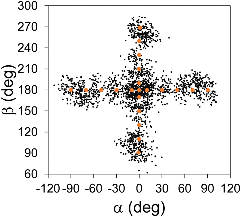 | ||
| Fig. 4 Distribution of IM data points in conformational space, projected on the (α, β) plane. The initial data points are denoted with larger orange dots, and the other data points sampled from iterative MD simulations are denoted with smaller black dots. | ||
4.3. Effect of adding customized-weighting coordinates
For this analysis, let us compare the IM potentials with and without the customized-weighting coordinate, namely, the torsional angle of H13–C11–C12–H15 (Fig. 1). Although this coordinate depends only on the torsional motion between the two hydrogen atoms, it is still closely related to the definition of HOOP.75 Thus, we can expect that the S1 state potential energy and its derivative will likely change sensitively with this torsional displacement, while the Cartesian distance function (dn(X) in eqn (6)) will rather be insensitive to the same displacement. This will make the torsion of H13–C11–C12–H15 a plausible choice. For the parameter τi in eqn (9), we tested the initial interpolation database with a few different values and found that 0.3 rad was appropriate. A more systematic determination may be possible, but the overall shape of the interpolated PES was not too sensitive to a small change in the parameter τi.Fig. 5 presents the interpolated S1 PESs projected on the (β, HOOP)-plane in the vicinity of the S0-optimized geometry, with and without the customized weighting coordinate. For direct comparisons, the reference QM PES based on α-CASSCF is also drawn in the figure. The plots for the S0 state PESs can also be found in Fig. S5 (ESI†). From Fig. 5a, we can already see some additional irregularities on the PES without the customized weighting scheme, which are not eliminated even after increasing the database size. Especially, the two plots show qualitative differences in the upper right and the lower left regions, and the S1 state energy is significantly underestimated without using our new weighting scheme. This underestimation will seriously distort simulated trajectories toward fictitiously low energy sides,58 and this aspect clearly demonstrates the need for adopting the customized weighting coordinate. The irregularities do not disappear with the growth in the database size to N = 2100 in Fig. 5b and c, whether we adopt one-part or two-part weighting schemes, even though the underestimations in the S1 potential were partly alleviated. With this observation, it is natural to anticipate that blindly increasing the database size with the GROW scheme will not provide any reliability unless the target-customized weighting coordinate is introduced. One might wonder that the error could have been induced by a limited number of ill-behaved data points in the region with large HOOP values. Namely, the error might be more about the locations of the data points rather than the choice of the weighting coordinate. The lack of reliability even with the two-part weight function shown in Fig. 5c straightforwardly negates this possibility. In general, adopting the two-part weight function using confidence radii has been proven to be effective in reducing the error associated with ill-behaved data points. Indeed, for the PESs with customized weighting coordinates, improvements from Fig. 5b to c are quite noticeable. The procedures for determining the confidence radii for the two-part weight function can be found in ESI.†
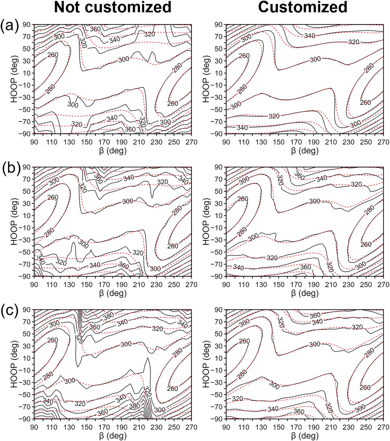 | ||
| Fig. 5 Contour plots of the interpolated (solid black) and the reference QM (dashed red) S1 PES's in kJ mol−1 around the Franck–Condon region, without using the target-customized weighting coordinate (left panels) and with using it (right panels). In (a), the weights are based on the one-part weight function and the database is with the 21 initial data points. In (b), the number of the data points was increased to 2100 with the same weighting scheme. Finally, in (c), the weights are based on the two-part weight function. | ||
While the contour maps of the PESs in Fig. 5 give us insights into the interpolation errors as functions of two key twisting degrees of freedom, it remains to be seen whether the observed interpolation errors may have meaningful impacts on the dynamics followed by MD simulations. To address this question, a series of test configurations were generated with MD simulations for additional comparisons of the interpolated PESs with and without the customized weighting coordinate. Because using one or the other interpolated PES for this configuration generation may not be fair for the comparison, we extracted 100 chromophore geometries from trajectory snapshots of a condensed-phase MD simulation based on a pure MM potential, by adopting the same MM-level simulation protocol as described in Section 3.3. Then, each geometry was further manipulated by rigidly rotating the α and the β torsional angles into pre-defined values to collect the actual test configurations that cover the entire α/β range. The pre-defined angle values were α = ±10, ±20, …, ±90 deg paired with β = 180 deg, and α = 0 deg paired with β = 90, 100, …, 270 deg, resulting in 37 angle pairs to generate a total of 3700 test configurations.
The IM errors with and without the customized weighting coordinate at these test configurations are presented in Fig. 6 for both S0 and S1 states together with their gap. The RMS errors can also be found in Table 2. While the error levels from the two PESs are almost the same in the case of S0, there is a significant difference with the S1 state. The lower level of errors with S0 can be easily understood from the chemical nature of the chromophore. The chromophore is more rigid in S0 and its PES is highly harmonic with a single energy minimum in 90° < β < 270°, as shown in Fig. S5 (ESI†). Thus, the S0 Hessian values will not vary much over the tested configurations, and even an incorrect weighting within interpolation will suffer to a lesser extent. In contrast, the S1 PES is much more complicated with multiple minima and strongly varying Hessian (Fig. 5), and correct weighting becomes more of an issue. Especially, due to the inevitable discrepancy between MM and IM potentials, some of the test configurations will unavoidably demand extrapolating situations, and Hessian errors induced by a less reliable weighting scheme will become a larger concern. This explains why the interpolation error is larger in S1 and how our scheme with the added weighting coordinate improves the surface fidelity. Finally, in the case of the S0–S1 gap energy, we can observe a significant cancellation of errors and the resulting RMS errors are as small as 0.050 eV and 0.088 eV, with and without the customized weighting coordinate. The error cancellation is related to spectator degrees of freedom such as C–H bond stretching, for which the associated interpolation errors are very similar in both electronic states. Similar cancellation of interpolation errors between S0 and S1 states was also observed in an earlier study.57
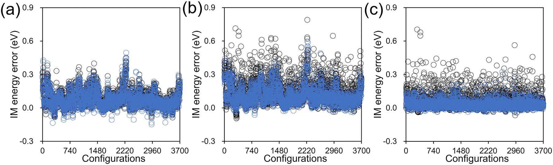 | ||
| Fig. 6 Interpolation errors in (a) the S0 state energy, (b) the S1 state energy, and (c) the S0–S1 gap from the 3700 test configurations, obtained with (blue) and without (black) the customized weighting coordinate. | ||
| Customized weighting | S0 | S1 | S0–S1 gap |
|---|---|---|---|
| Not used | 0.108 | 0.174 | 0.088 |
| Used | 0.103 | 0.137 | 0.050 |
Potential energy curves along the α/β coordinates of some selected test configurations are plotted in Fig. 7. In all cases in the figure, the most significant difference between the IM PESs with and without the customized weighting is observed for the β-twisting barrier in the S1 state. This is indeed expected from what we already observed in Fig. 5b. In any case, this implies that the IM errors resulting from not using our new scheme may have a serious effect on the excited state twisting dynamics in the condensed phase. In contrast, along α, there is almost no difference between the two interpolated potential curves whether the customized weighting is used or not; although likely in some extrapolation cases, there also are noticeable errors in the α-twisted geometries as shown in Fig. 7c, and the customized weighting again remedies the issue quite satisfactorily. These facts show that the added weighting coordinate, which is related to the HOOP coordinate, does not only improve the β-twisting behavior, but also the α-twisting.
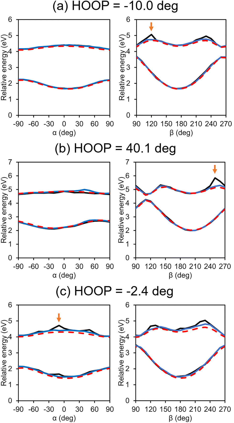 | ||
| Fig. 7 Interpolated potential energy curves along α and β for some selected test configurations with (blue) and without (black) the customized weighting scheme. For comparison, reference QM results are also shown (red). Arrows mark the points that will be adopted for further analyses in Fig. 8. | ||
To characterize how our new weighting scheme improves the energy prediction with the same set of database, we picked up three configurations with large energy errors from Fig. 7. At each configuration, we estimated the Taylor expansion errors from all individual data points and associated them with their contributions to the final interpolation. The results are pictorially provided in Fig. 8. Here, for each of the three configurations, we are showing a series of properties: the conventional Cartesian distance between the configuration and a given data point (horizontal axis), the added distance between the same pair in terms of the customized weighting coordinate (vertical axis), how importantly the given data point is contributing to the final interpolation (circle size), and the size of the energy error in the Taylor expansion from the given data point (color). For the energy error, we adopted the S0–S1 gap energy. We are showing only the results from the top-contributing data points, whose number was determined from the IPR value in eqn (11). Fig. 8 clearly shows that the main contributors to the IM error without the customized weighting coordinate are the terms with small Cartesian distances and large customized weighting distances, regardless of the IPR values or the identity among the three chosen configuration. When the customized weighting is introduced in the interpolation, such erroneous points do not contribute any more, and the IM errors are reduced to below 0.2 eV.
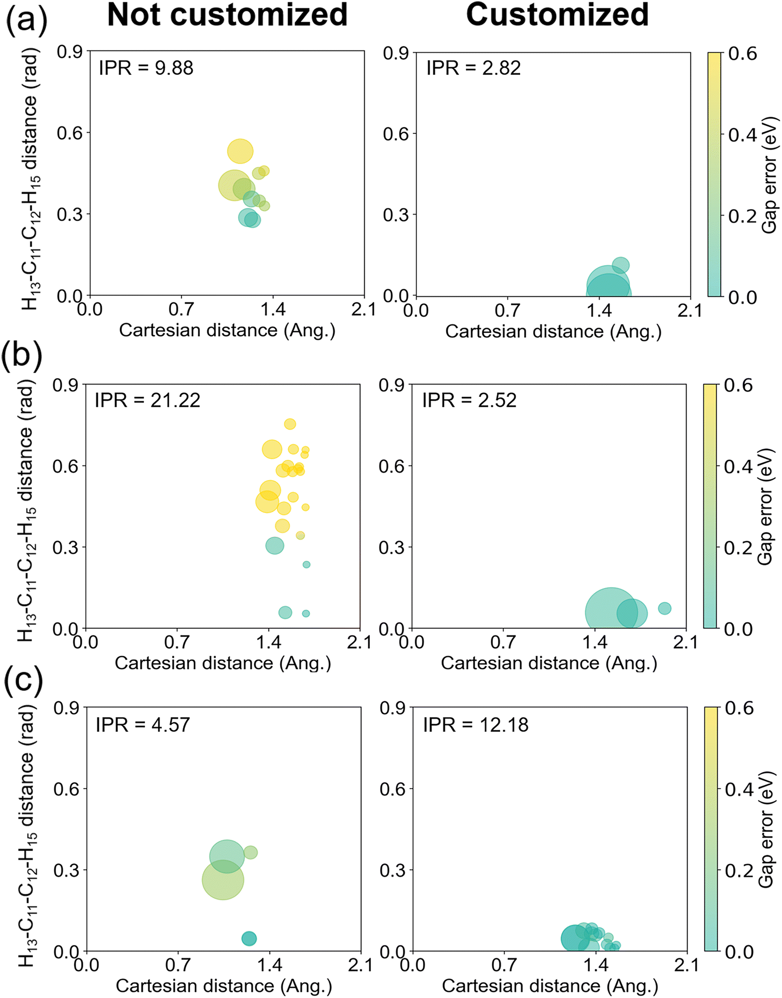 | ||
| Fig. 8 Errors of the Talyor expansions on the S0–S1 gap energy from the mainly participating data points to the final Shepard's interpolation. The horizontal and the vertical axes denote the distances of each data point in terms of conventional Cartesian coordinates and in terms of the newly added customized weighting coordinate, respectively. Left/right panels show the cases without/with including customized weighting coordinate to the interpolation weights. The configurations in (a), (b), and (c) correspond to the points marked with arrows in Fig. 7. The size of a circle is proportional to the relative magnitude of the interpolation weight, and the size of the error is represented in colors. The IPR value for each weighted summation, which corresponds to the number of circles in each panel, is also shown for reference. | ||
Before moving to the next section, let us discuss the choice of the added weighting coordinates. In fact, one simple numerical test for this choice can be a correlation analysis between the interpolation error and the displacement in the direction of a particular internal coordinate by following the definition of δi,n in eqn (9), potentially without any tolerance parameter. Indeed, we performed this simple test based on Pearson's correlation coefficient with the test configurations, and the test did suggest that the torsion of H13–C11–C12–H15 would be the most plausible one. The values of the correlation coefficients are listed in Tables S4–S7 (ESI†). The largest correlation was found with the torsion of H13–C11–C12–H15 with a correlation coefficient of 0.3723, while the ones for most of the other degrees of freedoms were below 0.2. Interestingly, other internal coordinates with significant correlations were also closely related to the isomerization and/or the charge transfer of the chromophore: C2–O17 bond stretching (0.3326), C5–C11 bond stretching (0.3074), and H13–C11–C12–C14 proper dihedral (0.2962). Thus, our intuition-based selection can be mathematically rationalized quite well. More importantly, this test suggests a systematic way of selecting the customized coordinate(s) in a more general sense. Even still, we emphasize that the actual choice will still heavily rely on the intrinsic character of a given chemical system and its reaction pathway, and we expect that the decision should be made based on chemistry.
In relation to this, there is a possibility of directly adopting HOOP as the customized coordinate. Not surprisingly, the effective distance in HOOP also strongly correlated with the interpolation error. The computed correlation coefficient for the HOOP coordinate was 0.3361, at a slightly lower level than the H13–C11–C12–H15 torsion. Therefore, we expect similar results would be attained even when HOOP is selected as the customized coordinate. Besides, because HOOP is defined as a difference between two torsional angles, its use will likely introduce unnecessary complications compared to using H13–C11–C12–H15. We also emphasize that the definition of effective distance shown in eqn (9) can indeed inclusively handle the case of choosing a linear combination of multiple internal coordinates such as HOOP. In general, when one finds multiple internal coordinates that are similarly correlated with the interpolation error, adopting them together or taking their linear combination may be the right tactic to follow. We anticipate that some symmetric molecules would behave in this manner.
4.4. Application to dynamics simulations
To demonstrate the applicability of the interpolated PES with our new weighting scheme, we performed IM/MM NAMD simulations of the PYP chromophore in an aqueous solution as detailed in Section 3.4. For comparisons, the IM PESs prepared at different levels of quantum chemical theories were employed, and the simulated S1 state population decays were monitored. Fig. 9 presents the results with the fitted time constants of 0.23, 0.28, and 0.47 ps, respectively, for IM/MM PES's based on SA-CASSCF, α-CASSCF, and MS-CASPT2.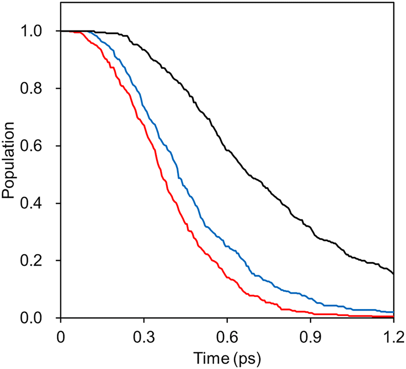 | ||
| Fig. 9 Decays of the S1 state populations from NAMD simulations with IM/MM PES's based on SA-CAS(4,3)SCF (red), α-CAS(4,3)SCF (blue), and MS-CAS(4,3)PT2 (black). In the MS-CASPT2 case, the dual-level approximation was adopted by replacing the Hessians with the ones obtained at the α-CASSCF level. | ||
Probably, what is more important than each numerical value is the fact that the α-CASSCF level dynamics appeared more closely to the SA-CASSCF level dynamics, rather than the MS-CASPT2 one. This was caused by the fact that the β-twisting barrier is underestimated by both SA-CASSCF and α-CASSCF, which can be easily seen in Fig. 3 and was also already discussed in an earlier report.106 The hopping geometries projected on the (α, β) plane presented in Fig. 10 also show that a significant fraction of the S1 state population undergoes decay through the β-twisting channel with SA-CASSCF and α-CASSCF, whereas transitions through that channel are negligibly observed with MS-CASPT2. These aspects clearly underscore the necessity of comparative analyses on the reaction pathways obtained with different levels of theories.
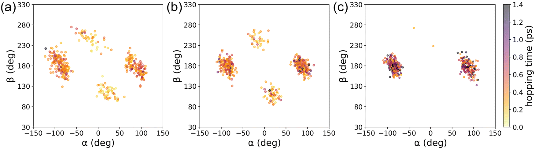 | ||
| Fig. 10 Distributions of the hopping geometries from IM/MM NAMD simulations based on (a) SA-CAS(4,3)SCF, (b) α-CAS(4,3)SCF, and (c) MS-CAS(4,3)PT2 levels of theories. | ||
Because the energy gap is one of the key deciding factors for hopping with NAMD simulations, we further inspected the degree of agreements between the IM S0–S1 gap energies and their reference QM values at the collected hopping geometries. The results are provided in Fig. 11, and they show that there are no exceptionally outlying IM errors. The RMS errors from the correlation plots are 0.056, 0.020, and 0.033 eV for the cases of the SA-CASSCF, α-CASSCF, and MS-CASPT2, respectively. These RMS errors are comparable to the 0.050 eV value found in Table 2, computed with the 3700 test configurations. The increased error with SA-CASSCF is likely due to the level discrepancy between the one used for conducting IM/MM simulations and the one used for the database sampling. In the case of MS-CASPT2, additional errors could have stemmed from the approximate nature of the adopted dual-interpolation scheme.33 In fact, this effect of the dual interpolation is more pronounced on the IM errors in individual S0 and S1 state energies (Table S8, ESI†), but they tend to cancel out each other toward the S0–S1 gap estimations. In any case, the definitely low level of RMS error of 0.033 eV is encouraging toward performing NAMD simulations with the dual-interpolation scheme. Of course, one should still care to achieve an enough fidelity with enough data points along the possible excited-state decay channels.
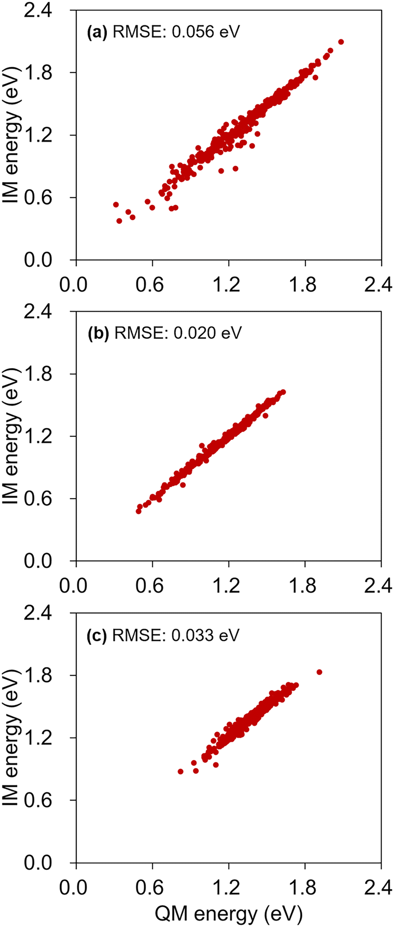 | ||
| Fig. 11 Correlations between the IM S0–S1 gap energies and the reference QM energies, calculated at the hopping geometries, obtained with IM/MM PES's based on (a) SA-CAS(4,3)SCF, (b) α-CAS(4,3)SCF, and (c) MS-CAS(4,3)PT2. RMS error values are also shown in each panel. | ||
5. Concluding remarks
In this work, we proposed a new weighting scheme for the IM/MM tactic,54,58 for enhancing its capability. The scheme adopts additional weighting coordinates, which need to be chosen in a system-specific manner. By adopting the new weighting scheme with the PYP chromophore, semi-global PESs could be successfully constructed for both S0 and S1 electronic states in combination with their charge-localized diabatic representations. In total, 2100 data points were prepared to cover the entire excited-state decay pathways along two important torsional coordinates. During the course of data point collection, a modification on the conventional GROW scheme was devised to facilitate data point sampling. The improvements from using the new weighting scheme were analyzed with the constructed interpolation database. The results show that the new weighting scheme is essential for reducing interpolation errors, especially in relation to the β-twisting barriers of the PYP chromophore. The IM/MM potential models with the new weighting scheme were applied to performing condensed-phase nonadiabatic simulations of the chromophore. We believe that it will be straightforward to implement our new weighting scheme to other tactics of building molecular PESs such as the molecular mechanics with Shepard interpolation correction61 and the multiconfiguration molecular mechanics algorithm.50–52Indeed, the excited-state dynamics of the PYP complex continues to pose long-standing questions from both experimental and theoretical perspectives. Specifically, for example, both the detailed twisting pathway of the PYP chromophore in the complex and the key interactions within the complex that control the reaction barrier along the twisting pathway remain elusive.71,106,107 With our new weighting scheme and our new potential model that is as reliable as up to the MS-CASPT2 level of theory, we expect that new simulations of the excited-state dynamics of PYP can be performed. We hope that this may present an opportunity to answer some of the puzzling questions lingering around PYP, and we will report such results in due course.
Conflicts of interest
There are no conflicts of interest to declare.Acknowledgements
This work was supported by the Mid-Career Researcher Program (grant 2021R1A2C2094153) and by the Science Research Center (grant No. 2020R1A5A1019141) through the National Research Foundation (NRF) funded by the Ministry of Science and ICT of Korea.References
- J. C. Tully, J. Chem. Phys., 1990, 93, 1061–1071 CrossRef CAS.
- L. Wang, A. Akimov and O. V. Prezhdo, J. Phys. Chem. Lett., 2016, 7, 2100–2112 CrossRef CAS PubMed.
- B. F. E. Curchod and T. J. Martínez, Chem. Rev., 2018, 118, 3305–3336 CrossRef CAS.
- L. Bonnet, J. Chem. Phys., 2020, 153, 174102 CrossRef CAS.
- F. Agostini and E. K. U. Gross, Eur. Phys. J. B, 2021, 94, 179 CrossRef CAS.
- L. Du and Z. Lan, J. Chem. Theory Comput., 2015, 11, 1360–1374 CrossRef CAS.
- O. Weingart, A. Nenov, P. Altoè, I. Rivalta, J. Segarra-Martí, I. Dokukina and M. Garavelli, J. Mol. Model., 2018, 24, 271 CrossRef.
- S. Mai, P. Marquetand and L. González, Wiley Interdiscip. Rev.: Comput. Mol. Sci., 2018, 8, e1370 Search PubMed.
- S. Seritan, C. Bannwarth, B. S. Fales, E. G. Hohenstein, C. M. Isborn, S. I. L. Kokkila-Schumacher, X. Li, F. Liu, N. Luehr, J. W. Snyder Jr, C. Song, A. V. Titov, I. S. Ufimtsev, L.-P. Wang and T. J. Martínez, Wiley Interdiscip. Rev.: Comput. Mol. Sci., 2021, 11, e1494 CAS.
- D. Avagliano, M. Bonfanti, M. Garavelli and L. González, J. Chem. Theory Comput., 2021, 17, 4639–4647 CrossRef CAS PubMed.
- I. S. Lee, J.-K. Ha, D. Han, T. I. Kim, S. W. Moon and S. K. Min, J. Comput. Chem., 2021, 42, 1755–1766 CrossRef CAS.
- D. V. Cofer-Shabica, M. F. S. J. Menger, Q. Ou, Y. Shao, J. E. Subotnik and S. Faraji, J. Chem. Theory Comput., 2022, 18, 4601–4614 CrossRef CAS PubMed.
- M. Barbatti, M. Bondanza, R. Crespo-Otero, B. Demoulin, P. O. Dral, G. Granucci, F. Kossoski, H. Lischka, B. Mennucci, S. Mukherjee, M. Pederzoli, M. Persico, M. Pinheiro Jr, J. Pittner, F. Plasser, E. Sangiogo Gil and L. Stojanovic, J. Chem. Theory Comput., 2022, 18, 6851–6865 CrossRef CAS.
- M. Shakiba, B. Smith, W. Li, M. Dutra, A. Jain, X. Sun, S. Garashchuk and A. Akimov, Software Impacts, 2022, 14, 100445 CrossRef.
- V. M. Freixas, W. Malone, X. Li, H. Song, H. Negrin-Yuvero, R. Pérez-Castillo, A. White, T. R. Gibson, D. V. Makhov, D. V. Shalashilin, Y. Zhang, N. Fedik, M. Kulichenko, R. Messerly, L. N. Mohanam, S. Sharifzadeh, A. Bastida, S. Mukamel, S. Fernandez-Alberti and S. Tretiak, J. Chem. Theory Comput., 2023, 19, 5356–5368 CrossRef CAS PubMed.
- H. Lin and D. G. Truhlar, Theor. Chem. Acc., 2007, 117, 185–199 Search PubMed.
- H. M. Senn and W. Thiel, Angew. Chem., Int. Ed., 2009, 48, 1198–1229 CrossRef CAS PubMed.
- A. J. C. Varandas, in Advances in Chemical Physics, ed. I. Prigogine and S. A. Rice, John Wiley & Sons, Inc., Hoboken, New Jersey, 1 edn, 1988, vol. 74, pp. 255–338 Search PubMed.
- A. Aguado and M. Paniagua, J. Chem. Phys., 1992, 96, 1265–1275 CrossRef CAS.
- R. N. Porter and M. Karplus, J. Chem. Phys., 2004, 40, 1105–1115 CrossRef.
- B. J. Braams and J. M. Bowman, Int. Rev. Phys. Chem., 2009, 28, 577–606 Search PubMed.
- K. R. Yang, X. Xu and D. G. Truhlar, J. Chem. Theory Comput., 2014, 10, 924–933 CrossRef CAS PubMed.
- J. Ischtwan and M. A. Collins, J. Chem. Phys., 1994, 100, 8080–8088 CrossRef CAS.
- G. G. Maisuradze and D. L. Thompson, J. Phys. Chem. A, 2003, 107, 7118–7124 CrossRef CAS.
- C. Xu, D. Xie, D. H. Zhang, S. Y. Lin and H. Guo, J. Chem. Phys., 2005, 122, 244305 CrossRef.
- T. B. Blank, S. D. Brown, A. W. Calhoun and D. J. Doren, J. Chem. Phys., 1995, 103, 4129–4137 CrossRef CAS.
- T. S. Ho and H. Rabitz, J. Chem. Phys., 1996, 104, 2584–2597 CrossRef CAS.
- J. Behler and M. Parrinello, Phys. Rev. Lett., 2007, 98, 146401 CrossRef.
- R. M. Balabin and E. I. Lomakina, Phys. Chem. Chem. Phys., 2011, 13, 11710–11718 RSC.
- M. Rupp, A. Tkatchenko, K.-R. Müller and O. A. von Lilienfeld, Phys. Rev. Lett., 2012, 108, 058301 CrossRef.
- J. Cui and R. V. Krems, J. Phys. B: At., Mol. Opt. Phys., 2016, 49, 224001 CrossRef.
- S. Chmiela, A. Tkatchenko, H. E. Sauceda, I. Poltavsky, K. T. Schütt and K.-R. Müller, Sci. Adv., 2017, 3, e1603015 CrossRef.
- K. A. Nguyen, I. Rossi and D. G. Truhlar, J. Chem. Phys., 1995, 103, 5522–5530 CrossRef.
- Y. M. Rhee, T. G. Lee, S. C. Park and M. S. Kim, J. Chem. Phys., 1997, 106, 1003–1012 CrossRef CAS.
- T. Ishida and G. C. Schatz, J. Chem. Phys., 1997, 107, 3558–3568 CrossRef CAS.
- K. C. Thompson and M. A. Collins, J. Chem. Soc., Faraday Trans., 1997, 93, 871–878 RSC.
- K. C. Thompson, M. J. T. Jordan and M. A. Collins, J. Chem. Phys., 1998, 108, 8302–8316 CrossRef CAS.
- T. Taketsugu, N. Watanabe and K. Hirao, J. Chem. Phys., 1999, 111, 3410–3419 CrossRef CAS.
- R. P. A. Bettens and M. A. Collins, J. Chem. Phys., 1999, 111, 816–826 CrossRef CAS.
- T. Ishida and G. C. Schatz, Chem. Phys. Lett., 1999, 314, 369–375 CrossRef CAS.
- Y. M. Rhee, J. Chem. Phys., 2000, 113, 6021–6024 CrossRef CAS.
- M. A. Collins, Theor. Chem. Acc., 2002, 108, 313–324 Search PubMed.
- H. Wang and R. P. A. Bettens, Phys. Chem. Chem. Phys., 2019, 21, 4513–4522 RSC.
- C. Crespos, M. A. Collins, E. Pijper and G. J. Kroes, Chem. Phys. Lett., 2003, 376, 566–575 CrossRef CAS.
- P. N. Abufager, C. Crespos and H. F. Busnengo, Phys. Chem. Chem. Phys., 2007, 9, 2258–2265 RSC.
- C. R. Evenhuis, X. Lin, D. H. Zhang, D. Yarkony and M. A. Collins, J. Chem. Phys., 2005, 123, 134110 CrossRef PubMed.
- O. Godsi, C. R. Evenhuis and M. A. Collins, J. Chem. Phys., 2006, 125, 104105 CrossRef PubMed.
- O. Godsi, M. A. Collins and U. Peskin, J. Chem. Phys., 2010, 132, 124106 CrossRef PubMed.
- J. W. Park and Y. M. Rhee, J. Chem. Phys., 2014, 140, 164112 CrossRef PubMed.
- Y. Kim, J. C. Corchado, J. Villà, J. Xing and D. G. Truhlar, J. Chem. Phys., 2000, 112, 2718–2735 CrossRef CAS.
- M. Higashi and D. G. Truhlar, J. Chem. Theory Comput., 2008, 4, 790–803 CrossRef CAS PubMed.
- M. Higashi and D. G. Truhlar, J. Chem. Theory Comput., 2008, 4, 1032–1039 CrossRef CAS.
- J. W. Park, H. W. Kim, C.-I. Song and Y. M. Rhee, J. Chem. Phys., 2011, 135, 014107 CrossRef PubMed.
- J. W. Park and Y. M. Rhee, J. Phys. Chem. B, 2012, 116, 11137–11147 CrossRef CAS PubMed.
- J. W. Park and Y. M. Rhee, ChemPhysChem, 2014, 15, 3183–3193 CrossRef CAS.
- J. W. Park and Y. M. Rhee, J. Chem. Theory Comput., 2014, 10, 5238–5253 CrossRef CAS PubMed.
- C. W. Kim and Y. M. Rhee, J. Chem. Theory Comput., 2016, 12, 5235–5246 CrossRef CAS PubMed.
- Y. M. Rhee and J. W. Park, Int. J. Quantum Chem., 2016, 116, 573–577 CrossRef CAS.
- M. Higashi and S. Saito, J. Phys. Chem. Lett., 2011, 2, 2366–2371 CrossRef CAS.
- J. W. Park and Y. M. Rhee, J. Am. Chem. Soc., 2016, 138, 13619–13629 CrossRef CAS PubMed.
- M. Higashi and S. Saito, J. Chem. Theory Comput., 2016, 12, 4128–4137 CrossRef CAS PubMed.
- C. W. Kim, B. Choi and Y. M. Rhee, Phys. Chem. Chem. Phys., 2018, 20, 3310–3319 RSC.
- S. Saito, M. Higashi and G. R. Fleming, J. Phys. Chem. B, 2019, 123, 9762–9772 CrossRef PubMed.
- J. Behler, J. Chem. Phys., 2016, 145, 170901 CrossRef PubMed.
- P. O. Dral, J. Phys. Chem. Lett., 2020, 11, 2336–2347 CrossRef CAS PubMed.
- O. T. Unke, S. Chmiela, H. E. Sauceda, M. Gastegger, I. Poltavsky, K. T. Schütt, A. Tkatchenko and K.-R. Müller, Chem. Rev., 2021, 121, 10142–10186 CrossRef CAS PubMed.
- J. Zhang, D. Chen, Y. Xia, Y.-P. Huang, X. Lin, X. Han, N. Ni, Z. Wang, F. Yu, L. Yang, Y. I. Yang and Y. Q. Gao, J. Chem. Theory Comput., 2023, 19, 4338–4350 CrossRef CAS.
- G. Wald, Science, 1968, 162, 230–239 CrossRef CAS PubMed.
- O. P. Ernst, D. T. Lodowski, M. Elstner, P. Hegemann, L. S. Brown and H. Kandori, Chem. Rev., 2014, 114, 126–163 CrossRef CAS PubMed.
- I. Schapiro, M. N. Ryazantsev, L. M. Frutos, N. Ferré, R. Lindh and M. Olivucci, J. Am. Chem. Soc., 2011, 133, 3354–3364 CrossRef CAS PubMed.
- S. Gozem, H. L. Luk, I. Schapiro and M. Olivucci, Chem. Rev., 2017, 117, 13502–13565 CrossRef CAS PubMed.
- O. Weingart, P. Altoè, M. Stenta, A. Bottoni, G. Orlandi and M. Garavelli, Phys. Chem. Chem. Phys., 2011, 13, 3645–3648 RSC.
- N. Klaffki, O. Weingart, M. Garavelli and E. Spohr, Phys. Chem. Chem. Phys., 2012, 14, 14299–14305 RSC.
- F. Andel, J. T. Murphy, J. A. Haas, M. T. McDowell, I. van der Hoef, J. Lugtenburg, J. C. Lagarias and R. A. Mathies, Biochemistry, 2000, 39, 2667–2676 CrossRef CAS PubMed.
- E. V. Gromov, I. Burghardt, H. Köppel and L. S. Cederbaum, J. Phys. Chem. A, 2011, 115, 9237–9248 CrossRef CAS PubMed.
- T. E. Meyer, Biochim. Biophys. Acta, 1985, 806, 175–183 CrossRef CAS PubMed.
- K. J. Hellingwerf, J. Hendriks and T. Gensch, J. Phys. Chem. A, 2003, 107, 1082–1094 CrossRef CAS.
- O. Valsson and C. Filippi, J. Chem. Theory Comput., 2010, 6, 1275–1292 CrossRef CAS.
- M. E. Martin, F. Negri and M. Olivucci, J. Am. Chem. Soc., 2004, 126, 5452–5464 CrossRef CAS PubMed.
- J. W. Park and T. Shiozaki, J. Chem. Theory Comput., 2017, 13, 3676–3683 CrossRef CAS PubMed.
- E. B. Wilson, J. C. Decius and P. C. Cross, Molecular Vibrations: The Theory of Infrared and Raman Vibrational Spectra, McGraw Hill, New York, 1955 Search PubMed.
- M. J. T. Jordan, K. C. Thompson and M. A. Collins, J. Chem. Phys., 1995, 103, 9669–9675 CrossRef CAS.
- H.-J. Werner, P. J. Knowles, G. Knizia, F. R. Manby and M. Schütz, et al., MOLPRO, version 2010.1, a package of ab initio programs, 2010, https://www.molpro.net Search PubMed.
- H. J. Werner and P. J. Knowles, J. Chem. Phys., 1985, 82, 5053–5063 CrossRef CAS.
- P. J. Knowles and H.-J. Werner, Chem. Phys. Lett., 1985, 115, 259–267 CrossRef CAS.
- H.-J. Werner, Mol. Phys., 1996, 89, 645–661 CrossRef CAS.
- R. Ditchfield, W. J. Hehre and J. A. Pople, J. Chem. Phys., 1971, 54, 724–728 CrossRef CAS.
- W. J. Hehre, R. Ditchfield and J. A. Pople, J. Chem. Phys., 1972, 56, 2257–2261 CrossRef CAS.
- P. C. Hariharan and J. A. Pople, Theor. Chim. Acta, 1973, 28, 213–222 CrossRef CAS.
- M. M. Francl, W. J. Pietro, W. J. Hehre, J. S. Binkley, M. S. Gordon, D. J. DeFrees and J. A. Pople, J. Chem. Phys., 1982, 77, 3654–3665 CrossRef CAS.
- J. W. Snyder, Jr., R. M. Parrish and T. J. Martínez, J. Phys. Chem. Lett., 2017, 8, 2432–2437 CrossRef.
- V. Hornak, R. Abel, A. Okur, B. Strockbine, A. Roitberg and C. Simmerling, Proteins: Struct. Funct. Bioinform., 2006, 65, 712–725 CrossRef CAS PubMed.
- C. I. Bayly, P. Cieplak, W. Cornell and P. A. Kollman, J. Phys. Chem., 1993, 97, 10269–10280 CrossRef CAS.
- J. Wang, R. M. Wolf, J. W. Caldwell, P. A. Kollman and D. A. Case, J. Comput. Chem., 2004, 25, 1157–1174 CrossRef CAS PubMed.
- B. Hess, C. Kutzner, D. van der Spoel and E. Lindahl, J. Chem. Theory Comput., 2008, 4, 435–447 CrossRef CAS PubMed.
- B. Hess, H. Bekker, H. J. C. Berendsen and J. G. E. M. Fraaije, J. Comput. Chem., 1997, 18, 1463–1472 CrossRef CAS.
- H. J. C. Berendsen, J. P. M. Postma, W. F. van Gunsteren, A. DiNola and J. R. Haak, J. Chem. Phys., 1984, 81, 3684–3690 CrossRef CAS.
- S. Nosé, J. Chem. Phys., 1984, 81, 511–519 CrossRef.
- M. Parrinello and A. Rahman, J. Appl. Phys., 1981, 52, 7182–7190 CrossRef CAS.
- X. Li, L. W. Chung, H. Mizuno, A. Miyawaki and K. Morokuma, J. Phys. Chem. Lett., 2010, 1, 3328–3333 CrossRef CAS.
- S. Olsen and R. H. McKenzie, J. Chem. Phys., 2009, 130, 184302 CrossRef PubMed.
- S. F. Boys, Rev. Mod. Phys., 1960, 32, 296–299 CrossRef CAS.
- T. Pacher, L. S. Cederbaum and H. Köppel, J. Chem. Phys., 1988, 89, 7367–7381 CrossRef CAS.
- E. V. Gromov, I. Burghardt, J. T. Hynes, H. Köppel and L. S. Cederbaum, J. Photochem. Photobiol. A: Chem., 2007, 190, 241–257 CrossRef CAS.
- S. Olsen and R. H. McKenzie, J. Chem. Phys., 2009, 131, 234306 CrossRef PubMed.
- M. Boggio-Pasqua, C. F. Burmeister, M. A. Robb and G. Groenhof, Phys. Chem. Chem. Phys., 2012, 14, 7912–7928 RSC.
- L. T. Mix, E. C. Carroll, D. Morozov, J. Pan, W. R. Gordon, A. Philip, J. Fuzell, M. Kumauchi, I. van Stokkum, G. Groenhof, W. D. Hoff and D. S. Larsen, Biochemistry, 2018, 57, 1733–1747 CrossRef CAS PubMed.
Footnote |
| † Electronic supplementary information (ESI) available. See DOI: https://doi.org/10.1039/d3cp05643k |
| This journal is © the Owner Societies 2024 |