Analysis of the piezo- and pyroelectric response of PVDF foils as fast particle detectors in pulsed supersonic jets
Received
29th February 2024
, Accepted 2nd July 2024
First published on 30th July 2024
Abstract
We report the design and performance of a new, rugged, general-purpose particle detector consisting of a stretched foil of polyvinylidene difluoride. Several detectors have been built and evaluated for applications in pulsed supersonic jet experiments where, e.g., particle density shall be measured with high time resolution. The working principle is that a directed bunch of particles, moving in vacuum, collides with the sensitive detector area and generates an electric charge. This charge generation is due to both the piezo- and the pyroelectric effect and results in a very fast detector response. In our detailed analysis of the detected signal, the piezoelectric contribution is defined by the constitutive equations of piezoelectricity, which are used in combination with the concept of a driven damped circular membrane allowing to obtain an analytic solution. The pyroelectric contribution is described via the exchanged energy between the impinging particle pulse and the detector foil. Because both the piezo- and the pyroelectric effects can be exploited, additional information about the particle impact such as the coefficient of energy accommodation or the coefficient of restitution can be determined experimentally.
1 Introduction
Droplet and nanoparticle impact phenomena are of immense significance both in nature and industrial applications. They appear in diverse fields such as aircraft icing, turbine engine operation, inkjet printing, raindrop impact, sputtering, spray coating, smart fabrics, virus transmission etc. A comprehensive understanding of the interactions between atoms, molecules, nanoparticles and surfaces is fundamentally important also in the field of in chemical physics. In order to shed more light upon the complex energy transfer processes, detectors with high sensitivity and good time resolution are essential. Accordingly, a large variety of detection techniques has been developed that may be roughly grouped into ionization, laser-based and accommodation methods,1 each with its own characteristics. Thermal detectors such as cryogenic bolometers or room temperature pyroelectric detectors depend on physical properties changing with temperature, i.e., the electrical resistance or the change of the spontaneous electrical polarization of the detector material.2 Detectors employing electret materials, e.g., polytetrafluoroethylene (PTFE), have been used as well, providing a response proportional to the momentum flux of the impacting particles.3 Here, we introduce a new detector suitable for the analysis of nano-size particles impacting a solid surface, based on a thin, conductively coated PVDF foil. Quantitative results on the exerted force and the transferred energy are obtained by developing a detailed model of both the piezo- and pyroelectric contributions of the detector response.
2 Experimental configuration
2.1 Supersonic jet
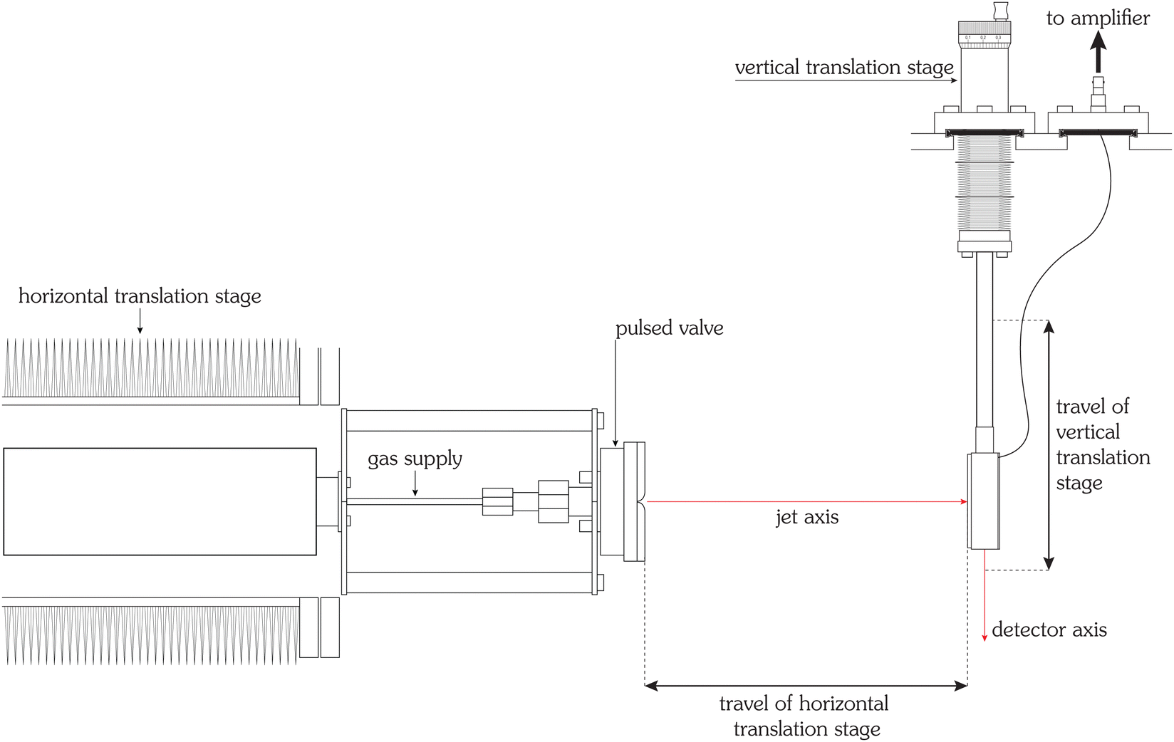
A well-established approach of generating clusters and nanoparticles in the gas phase is the powerful technique of supersonic jet expansions,4–6 allowing strong adiabatic cooling of gaseous substances during expansion and thus their nucleation and condensation into particles with size and speed adjustable in a wide range and a very systematic manner under well-defined vacuum conditions. Our experimental setup for generating a pulsed supersonic jet has been described in detail earlier.7–9 The relevant parts for this study are depicted in Fig. 1: a fast acting, pulsed valve10 produces ultra-short bursts of gas which expand through a parabolic nozzle with an opening diameter of 0.5 mm into an ultra-high vacuum chamber with a base pressure of 2 × 10⁻⁵ Pa. Nozzle diameter, background pressure and source pressure yield a position of the Mach disk that is several meters away from the nozzle so that collisions of the jet with background gas can be neglected. In order to minimize the bouncing of the spring-loaded plunger the control pulse duration of the valve is set to a very short time of 12 μs.11 The valve can be operated in a wide temperature range of 225.0 K to 415.0 K and with stagnation pressures from 0.30 MPa to 11.70 MPa. The gases are helium of 99.9999% purity and argon of 99.999% purity. An oscilloscope digitizes and visualizes the amplified detector signal, which then is transferred to a computer.
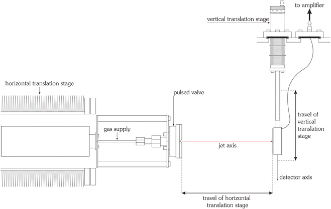 |
| | Fig. 1 Schematic figure of the experimental setup. A pulsed supersonic jet is obtained by expanding gas at high pressure through a pulsed, temperature-controlled valve (special Even-Lavie model) into vacuum. The valve is mounted on a precision translation stage, allowing to change the (horizontal) distance to the detector. The jet impinges on the PVDF detector, which is mounted on another (vertical) translation stage, allowing a movement perpendicular to the axis of the supersonic jet. Using these two translation stages it is possible to measure vertical beam profiles (and from these, determine the diameter of the jet) as a function of the horizontal position of the translation stage of the pulsed valve. This setup also allows to determine the distance between the virtual point source and the detector in situ and to determine the mean flow velocity of the jet, see text. In the experiments reported here, the typical distance between valve and detector is approx. 5 cm. An amplifier, located outside of the vacuum chamber, converts the generated charges into a voltage. The amplified voltage is recorded by a digital oscilloscope and read out by a personal computer. | |
2.2 PVDF as detector material
The sensitive part of the beam detector is a foil of polyvinylidene difluoride (PVDF). PVDF is a semi-crystalline fluoropolymer. It is synthesized by the polymerization of vinylidene fluoride, the resulting molecular chain consists of repeated (–CH2–CF2–) units. PVDF is chemically inert but highly electroactive. The electric activity is caused by the polar crystalline polymorph β, which has a planar, zigzag, all-trans conformation.12 This form is not centrosymmetric and possesses a spontaneous polarization and, therefore, it is piezoelectric and pyroelectric. The piezoelectric and pyroelectric response can be enhanced by stretching the foil, which transforms the non-polar, non-active α-PVDF to β-PVDF.13 Another possibility of achieving this phase change of PVDF is the application of a high electric field.12,14
Here, the used PVDF foil is both biaxially stretched and polarized by a high voltage.
2.3 Detector design
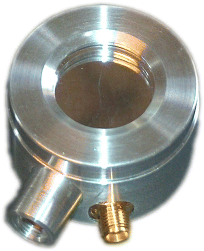
The molecular beam detectors, an example is shown in the photograph of Fig. 2, consist of a foil of PVDF with a thickness of 25 μm that is mounted on an aluminum ring. In this report the diameters of the sensitive area are 10.0 mm, 20.0 mm, 30.0 mm. Two configurations are studied: in the first, where the construction is similar to a trampoline, the PVDF foil is mounted elastically and can oscillate freely; in the other setup the PVDF foil is supported by an underlying disc such that the oscillations are strongly damped. The foil is coated on both sides with a roughly 200 nm thin aluminum layer for electric contact. In order to obtain a positive signal, the side of the PVDF foil with the positive pole during polarization is connected to the amplifier, the other side of the foil is grounded.
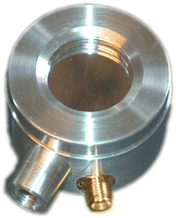 |
| | Fig. 2 Photograph of the PVDF detector with a sensitive diameter of 20 mm. On the lower left the thread for the attachment on the vertical translation stage is visible, next to it the electric connection for a 50 Ω coaxial cable. The four detectors used in this study were custom-built by one of the authors (KL, slt@pyrosensor.de), the conductively coated foils are available on request. | |
2.4 Amplification of the PVDF detector signal
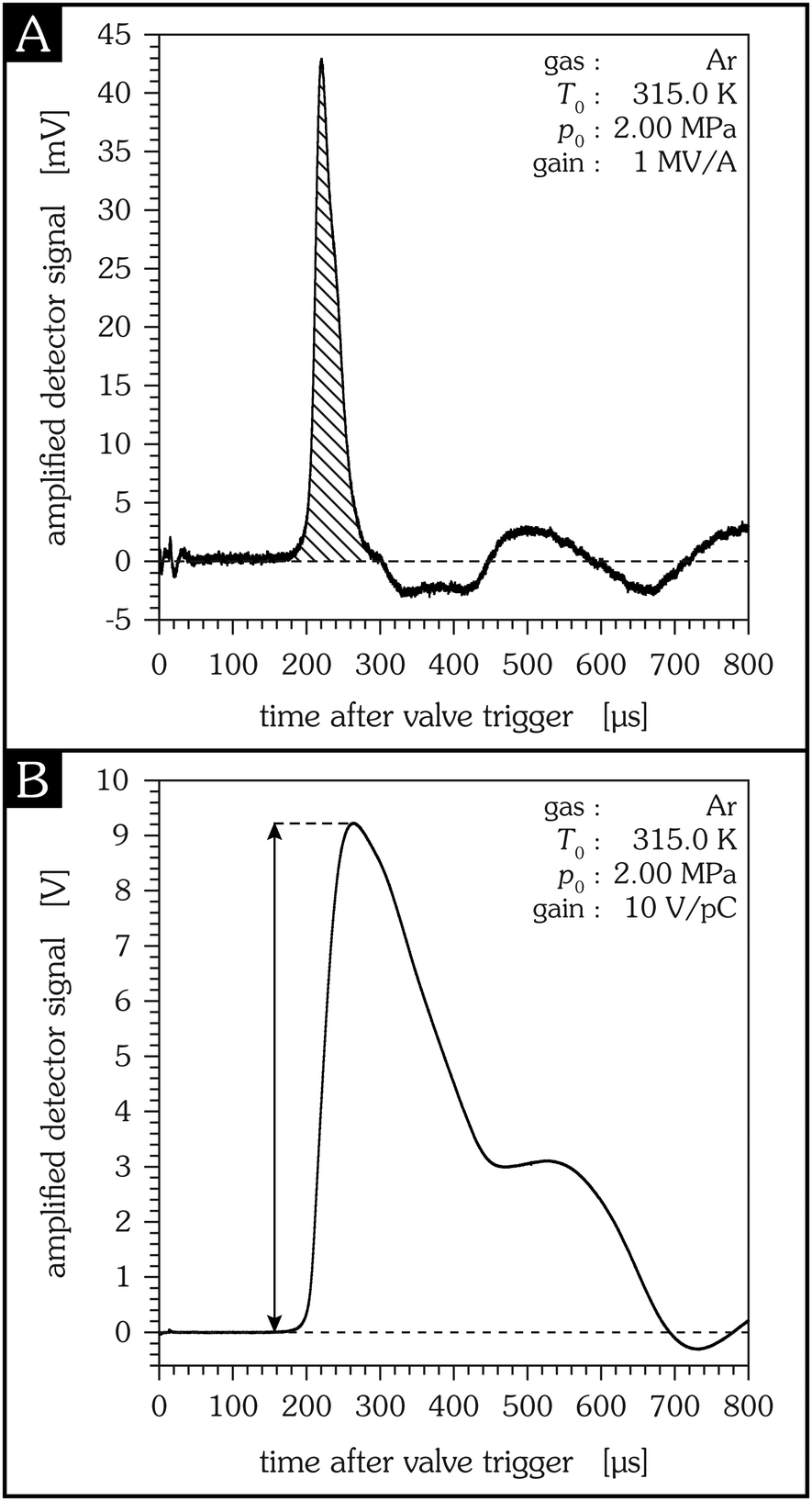
Because the amount of charges generated on the foil during particle impact is small, e.g., 7 × 10⁻²⁷ C per argon atom in Fig. 3, an amplifier is required to increase the signal of the PVDF detector to a level sufficiently high for recording it with a voltage measuring instrument. For this purpose, two different amplifiers are used in this study: a transimpedance amplifier and a charge amplifier. Both “amplifiers” actually transform the input signal, which is virtually grounded, into a voltage, see Fig. 4. The measured signal thus strongly depends on the type of amplifier used: for a transimpedance amplifier the generated charge is proportional to the cross-hatched area of Fig. 3A, for a charge amplifier it is proportional to the maximum signal amplitude of Fig. 3B.
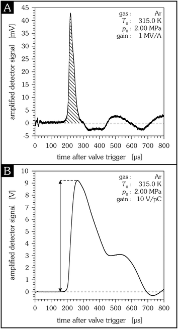 |
| | Fig. 3 Typical signal of the PVDF detector, measured with a transimpedance amplifier (A) and a charge amplifier (B), respectively. Source temperature is 315.0 K, source pressure is 2.00 MPa and the sensitive detector diameter is 20.0 mm in both cases. In the first 30 μs after triggering the pulsed valve an electric pickup signal can be detected, caused by the change of the electromagnetic field of the valve. The pickup signal consists of two peaks with the time difference given by the control pulse11 duration. For a transimpedance amplifier the generated charge is proportional to the cross-hatched area, for a charge amplifier it is proportional to the maximum signal amplitude. | |
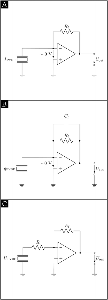 |
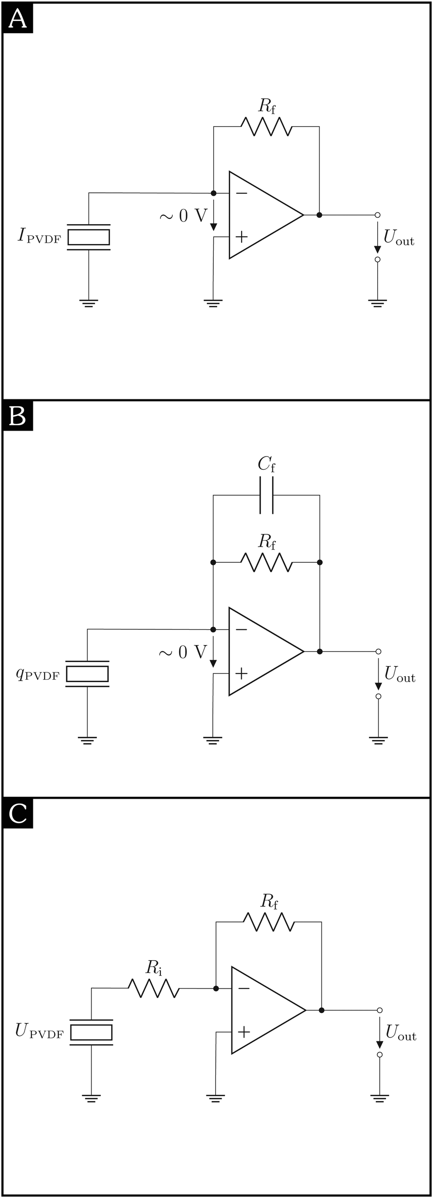
| | Fig. 4 Different detection schemes using a PVDF detector, which is connected to a (A) transimpedance amplifier, (B) charge amplifier, (C) voltage amplifier. | |
2.4.1 Transimpedance amplifier.
In one series of measurements a transimpedance amplifier SR570 from Stanford research systems is used. It converts a current into a voltage, the gain depends on the feedback loop resistor Rf and is equivalent to a resistance, see Fig. 4A. In case of a low input impedance and a capacitance-free feedback loop, the temporal response of a transimpedance amplifier is only limited by its bandwidth, i.e., it is not affected by the detector capacitance. Advantages of this specific amplifier are that its sensitivity is adjustable over nine orders of magnitude, from 1 kV A−1 to 1 TV A−1, and that it provides different operation modes such as “high bandwidth” or “low noise”, plus additional filters.
Because current is the change of charge per time, the total charge generated due to the particle impact is correlated to the area of the amplified signal, cf.Fig. 3A.
2.4.2 Charge amplifier.
In another series of experiments a charge amplifier HQA-15M-10T from FEMTO with a fixed gain of 10 V pC−1 is connected to the detector output – it converts the generated charge into a voltage. The gain is inversely proportional to the capacitance Cf in the feedback loop, cf.Fig. 4B. The amplitude of the resulting voltage signal is proportional to the total generated charge, cf.Fig. 3B. Compared to the evaluation of the signal area in the case of a transimpedance amplifier the signal-to-noise ratio is better for a charge amplifier (provided an equivalent gain). In addition, because of the virtual ground, the small capacitances of the wires do not affect the measurement. The amplified signal is also independent of the capacitance of the PVDF detector provided that its source capacitance is in the operating range of the amplifier.15 If, however, the capacitance of the detector is too high, charges remain on the PVDF surface for a short time, resulting in a broadening of the signal and a possible decrease of the peak amplitude. For this specific amplifier this situation occurs for the 20 mm and 30 mm diameter detectors. An advantage of the charge amplifier is its comparatively large bandwidth of 15 MHz. But due to the time constant given by the capacitor Cf and the resistor Rf in the feedback loop, see Fig. 4B, the charge amplifier has a lower cut-off frequency of 250 Hz – the response corresponds to a high pass filter.
2.4.3 Voltage amplifier.
Another amplifier type used in piezoelectric applications16 is the voltage amplifier; here, both the input and the output signal are voltages and the gain depends on the ratio of the input and feedback resistors, Ri and Rf, respectively, see Fig. 4C. In contrast to charge and transimpedance amplifiers the detector output is not virtually grounded. Hence, the generated charges remain on the electrode and discharge through the input resistor Ri over time,17 the voltage can be measured.18 Thus, the input voltage of the amplifier is caused by the charging and discharging of the PVDF surface and is proportional to the total capacitance of the connected cables and of the PVDF detector and, thus, to the sensitive detector area. Because the output voltage is a multiple of the input voltage, the output voltage also depends on these capacitances. The time response of the amplifier output is determined by the discharge rate of the PVDF detector, given by the capacitance of the PVDF detector and the input resistance Ri of the connected voltage amplifier. The shape of the output signal corresponds to that of a charge amplifier.
3 Charge generation of PVDF due to the impact of a pulsed free jet
Due to the impact of a pulsed free jet on a PVDF foil surface charges are generated. Expanding a gas under high pressure into a vacuum results in a supersonic jet where the particles move almost collision-free and have a narrow velocity distribution. After a certain flight distance the particles, i.e., atoms, molecules or clusters, collide with the sensitive detector area. The force applied to the detector surface is given by the change of momentum of the impacting particles per time. It is maximum for an elastic process. On the other hand the kinetic energy transferred from the particles to the detector surface is maximized for an inelastic process.
The force exerted on the detector foil by the impacting pulsed supersonic jet and the resulting time-dependent current (piezoelectric effect) as well as the surface charges generated on the foil due to a temperature change caused by the inelastic particle–surface interactions (pyroelectric effect) are derived in the appendix. Here we focus on some characteristic properties and possible applications of this type of PVDF detector.
3.1 Time response of PVDF detectors
Having a new detector at hand raises the questions how the measured signal compares with the original gas pulse, and how the detector compares with other detector types, e.g., a fast ion gauge.
The time response of PVDF detectors depends on various parameters. For example, the piezoelectric contribution to the signal is caused by the vibration of the PVDF foil, see Section A.1. Therefore, the time response related to the piezoelectric effect is given by the eigenfrequencies of the PVDF foil and thus depends on the size and the tension of the PVDF foil. For the detectors used in this study the first eigenfrequencies are below 10 kHz, and therefore the rise time of the signal caused by the piezoelectric effect is not fast enough to use the detector as a real time monitor. For comparison, the temporal behaviour of the pyroelectric signal contribution is given by the cooling time constant which describes the heat loss of the PVDF foil due to radiation (vacuum) and thermal conductivity (aluminium ring). Because the cooling time constant is sufficiently high the temperature increase of the foil is proportional to the generated charge and the measured current of the first peak corresponds to the arrival time distribution of the particles, i.e., the rise time of the measured signal is virtually not affected by the cooling term; it can, however, result in an undershoot of the measured signal. Fig. 5 shows a direct comparison of the time response of the PVDF detector and the collision-induced fluorescence of electronically excited metastable He atoms for identical source conditions. Clearly, both rise times are comparable and thus PVDF detectors can be used as a real-time monitor of pulsed supersonic jets.
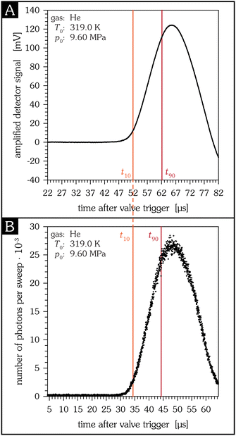 |
| | Fig. 5 Direct comparison of the PVDF detector measuring a supersonic jet of helium at high source pressure (A) and the collision-induced fluorescence of metastable helium atoms that are excited by a pulsed electron beam directly attached to the nozzle (B). In this way, the photon signal directly reflects the opening behaviour of the pulsed nozzle.8 The rise time of a signal is defined as the time the signal amplitude increases from 10% to 90% of the respective signal maximum. In (A) this t10/90 value is 10.1 μs, in (B) 9.9 μs. | |
One difference to other beam detectors is that PVDF detectors are both energy sensitive, such as a bolometer, and flux sensitive, such as an ion gauge.
Another difference is that these PVDF detectors do not require ionization which may be beneficial in certain applications, e.g., in bad background pressure conditions, when using corrosive gases, or when no light emission is wanted.
3.2 Determination of the radial jet density
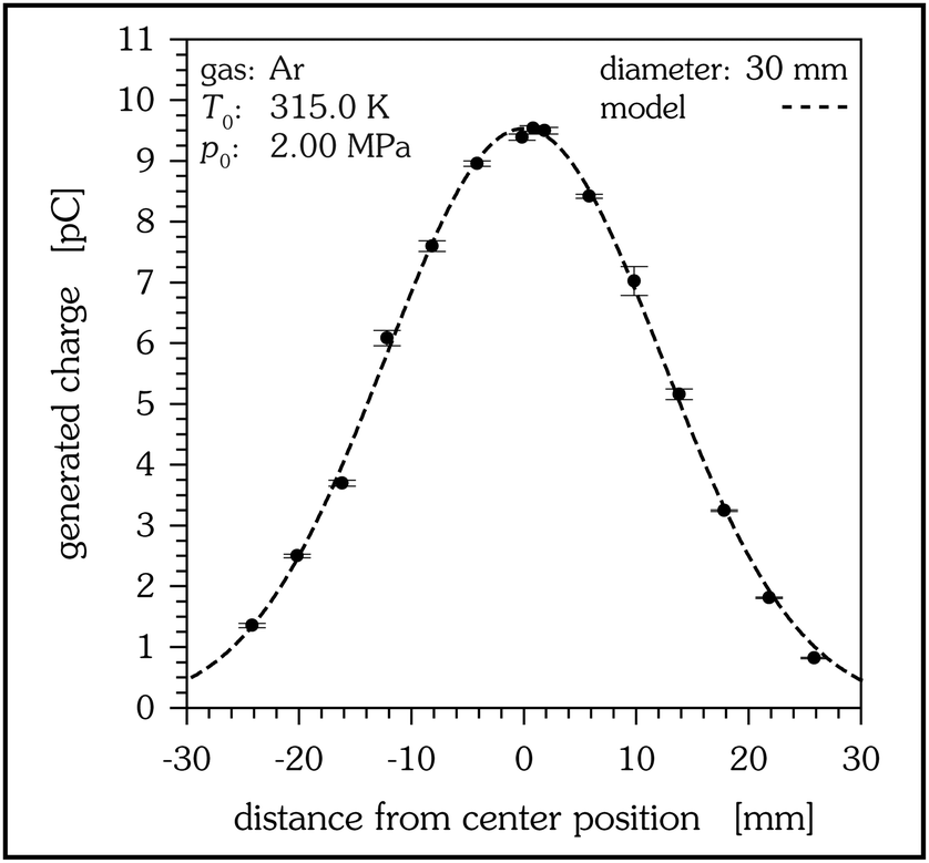
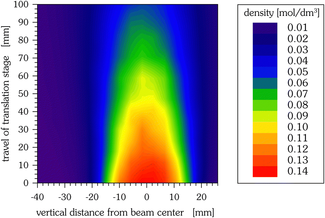
The particle density of a pulsed supersonic jet, resulting from an axially symmetric nozzle, can be expected to be radially symmetric. The expansion itself can be divided into a continuum region close to the nozzle and a free molecular region, where particle–particle collisions have ceased. In the latter region particle trajectories are straight streamlines which can be traced back to an origin named “virtual point source”. Thus, measuring radial density distributions as a function of the detector–nozzle distance permits to determine the location of this virtual source.19,20 Experimentally obtained jet profiles depend on the shape and the size of the sensitive detector area – and the density distribution of the supersonic jet. Only very small detector diameters can be used as a local jet probe, for the detectors investigated here the measured jet profile is a convolution of the radial distribution of the jet and the shape function of the sensitive detector area. Fig. 6 depicts a measurement of the radial distribution of the jet. Measuring the distance dependence of these radial distributions gives a linear dependence, as expected for the collision-free region, and allows to determine the plane of the virtual source. The signal measured at the vertical centre line can be used to calibrate the signal to the transferred energy of the impacting particles. The total number of particles per pulse is obtained from the signal of a cold-cathode ion gauge. The actual number of particles impacting the detector is derived from the radial particle distribution. Because the number of impacting particles is proportional to the generated charge, the spatially resolved jet density can be obtained as is shown in Fig. 7.
 |
| | Fig. 6 Experimental determination of the beam profile by the vertical movement of the detector. | |
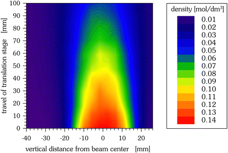 |
| | Fig. 7 Particle density of a supersonic helium jet (2.00 MPa, 315.0 K) as obtained from the two-dimensional beam density profile measurements, using the 30 mm detector. Per position, 32 measurements are averaged, each measurement being the average of 50 jet pulses, and with almost 300 positions measured. | |
3.3 Determination of the mean jet velocity
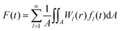
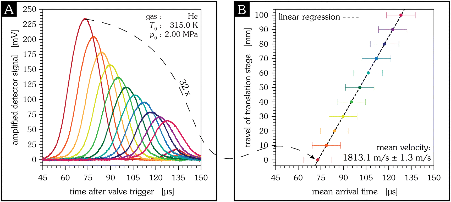
The mean velocity of the jet is measured by changing the horizontal distance between the nozzle and the detector.9 Due to the not precisely known time delay between the control pulse of the valve and the actual valve opening absolute arrival times aren't known and the jet velocity cannot be determined by one single measurement. Instead, the distance between nozzle and detector is changed using the precision translation stage and several measurements are taken. Plotting the travel of the horizontal translation stage versus the mean arrival time of the jet, obtained from the fit of the distribution function of an energy sensitive detector, yields a straight line, and its slope yields the mean jet velocity, despite the fact that absolute distances and absolute times aren't known. An example of this type of measurement is depicted in Fig. 8.
 |
| | Fig. 8 Determination of the mean velocity of a supersonic helium jet using the 30 mm detector in eleven different positions of the horizontal translation stage, indicated by different colours. Every measurement (averaged over 50 pulses) is repeated 32 times to give an estimate of the measurement uncertainty. Note that the distances given as travel of translation stage are relative lab coordinates and do not refer to an absolute detector–nozzle distance. The latter can be derived from the experimental determination of the virtual source, see Section 3.2. | |
4 Conclusions
A new detector for pulsed supersonic beams based on a thin, conductively coated PVDF foil has been designed, built and characterized. A detailed analysis of piezo- and pyroelectric contributions in pulsed particle–surface scattering experiments is presented which relates two different physical quantities – the transferred energy and the applied force of the impacting particles. The applied force is correlated to the piezoelectric effect where the amount of charges generated is proportional to the deflection of the vibrating PVDF foil. In an inelastic collision the impacting particles transfer energy to the PVDF foil which, as another result, heats up. Due to the pyroelectric effect this temperature increase generates charges. The total charge generated by both effects is amplified and measured.
The combined evaluation of these two physical quantities can be used to obtain the coefficient of restitution and the accommodation coefficient. Possible applications of such PVDF detectors are an in situ determination of the supersonic jet velocity, the mean particle density, or the mean particle size,21 which could allow, for example, studies of the correlation between particle size and accommodation coefficient.
Author contributions
Conceptualization, data curation, funding acquisition, project administration, software, supervision, validation and review editing by Wolfgang Christen, formal analysis, investigation, methodology, visualization and writing of the original draft by Paul Saftien, detector resources by Karsten Lange.
Conflicts of interest
There are no conflicts to declare.
Appendices
A Physical and mathematical background
A.1 Piezoelectric effect.
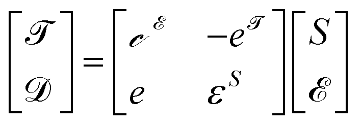
The impacting particles exert a force on the PVDF foil and deform it. Because of the asymmetric charge distribution of piezoelectric materials, the deformation results in a relative electric displacement of negative and positive partial charges against each other. The electric displacement is given by the constitutive equations of piezoelectric materials which describe the mechanical and the electrical behaviour of piezoelectric materials and here are given in the stress-charge form:22| | 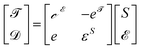 | (1) |
Here, ![[scr T, script letter T]](https://www.rsc.org/images/entities/char_e533.gif) represents mechanical stress, i.e., the force applied on the material surface normalized by the area of the surface,
represents mechanical stress, i.e., the force applied on the material surface normalized by the area of the surface, ![[scr D, script letter D]](https://www.rsc.org/images/entities/char_e523.gif) electric displacement, i.e., the sum of an external electric field
electric displacement, i.e., the sum of an external electric field ![[scr E, script letter E]](https://www.rsc.org/images/entities/char_e140.gif) and an induced dipole moment, and S strain, i.e., the deformation of the material in terms of a relative displacement. The material parameters of PVDF are the stiffness coefficients
and an induced dipole moment, and S strain, i.e., the deformation of the material in terms of a relative displacement. The material parameters of PVDF are the stiffness coefficients  , the coupling coefficients e, and the permittivity ε. The superscripts indicate the conditions held constant during measurement.
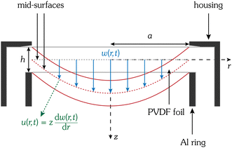
A.1.1 Definition of strains.
In our analysis the PVDF foil is treated according to the Kirchhoff–Love plate theory, which reduces a three-dimensional plate to the mid-surface plane of its two-dimensional representation. It includes the following assumptions:
, the coupling coefficients e, and the permittivity ε. The superscripts indicate the conditions held constant during measurement.
A.1.1 Definition of strains.
In our analysis the PVDF foil is treated according to the Kirchhoff–Love plate theory, which reduces a three-dimensional plate to the mid-surface plane of its two-dimensional representation. It includes the following assumptions:
• the foil is thin, i.e., its thickness h is much smaller than its radial dimension a; in our case this assumption is fulfilled well, the thickness-to-diameter ratio h/(2a) ranges from 8.3 × 10⁻⁴ to 25.0 × 10⁻⁴
• the foil thickness is constant, i.e., not affected by the impact of the particle jet
• mechanical deflections of the foil are small, such that Hooke's law applies, i.e., the deflection is proportional to the mean force exerted by the impinging particles
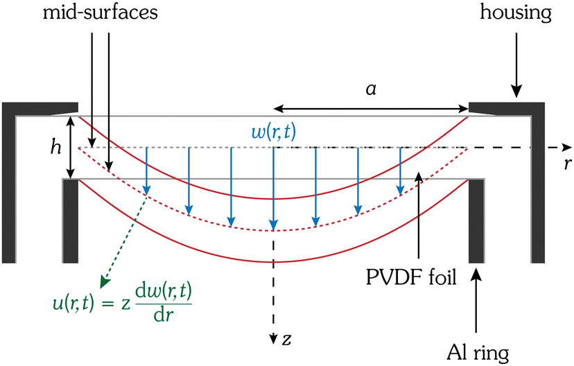
• lines normal to the mid-surface remain normal to the mid-surface when deformed, see Fig. 9.
 |
| | Fig. 9 Schematic sketch of an elastically mounted PVDF foil in the rest (grey lines) and deflected (red lines) position. The axial and radial displacements w(r,t) and u(r,t), respectively, are indicated. The axial displacement is given by the distance between the undeformed mid-surface (dashed grey line) and the deformed mid-surface (dashed red line). The radial displacement correlates with the derivative of the axial displacement. The z-axis corresponds to the beam axis. | |
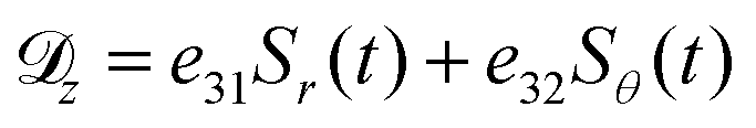
For a circular foil cylindrical coordinates are appropriate – these are the radial coordinate r, the tangential coordinate θ and the axial coordinate z. The centre position of the foil is the origin of the coordinate system. Accordingly, Sr and Sθ are mechanical strains in radial and tangential direction, respectively; both are caused by the elongation of the foil. The strain according to a compression is Sz, but because the thickness of the foil is assumed to be constant, Sz equals zero.
The PVDF foil is polarized in the direction of the axial axis. The axial component of the electric field z, however, equals zero because the PVDF foil is virtually grounded by the amplifier, see Fig. 4. Therefore, the electric displacement in z-direction according to eqn (1) is given by:
| | 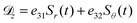 | (2) |
The parameters
e can be written as the product of the piezoelectric constants
d and the stiffness coefficients,

. Because only very small deflections occur,
e.g., in
Fig. 11 less than 35 μm for He and less than 20 μm for Ar, anisotropy is neglected and the stiffness coefficients

of an isotropic material are used and expressed by Young's modulus
Y and Possion's ratio
μ:
| | 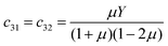 | (3) |
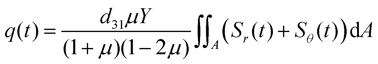
The piezoelectric constants
d31 and
d32 are equal, because the used PVDF foil is stretched biaxially. Hence, the amount of generated surface charges
q can be calculated by applying Gauss's law:
| |  | (4) |
Eqn (4) is integrated over the effective, sensitive detector area
A =
a2π, where
a is its radius. As current is the change of charge per time, the current is:
| | 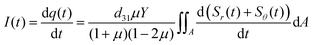 | (5) |
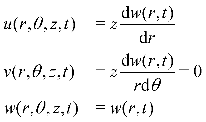
The deflection is described by the displacement fields u(r,θ,z,t), v(r,θ,z,t) and w(r,θ,z,t) in the radial, tangential and axial directions, respectively. They are all related to the axial displacement, see Fig. 9, given by:23
| | 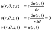 | (6) |
Only axisymmetric vibrations are considered and thus w is independent of θ and the tangential displacement field v equals zero. Accordingly, the strain components for small axial displacements are:
| | 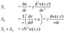 | (7) |
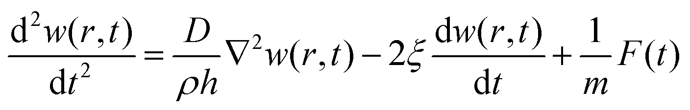
A.1.2 Driven vibration of a circular PVDF foil.
The axial displacement of a circular thin membrane due to vibration can be described by:24| | 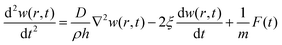 | (8) |
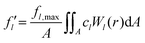
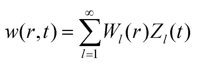
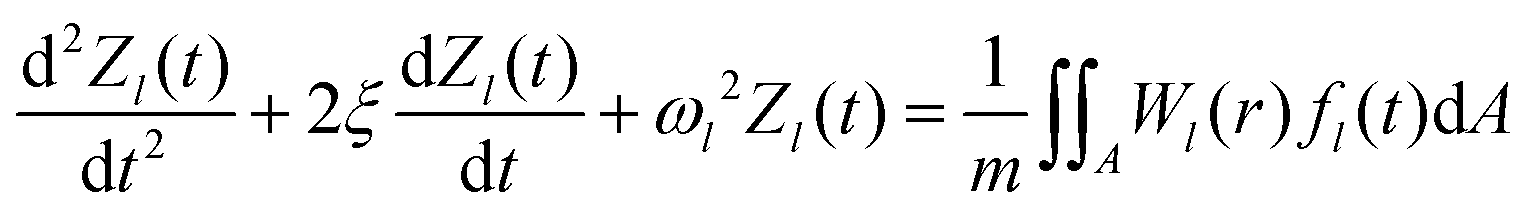
Here, D is the tension of the membrane, ρ the density of the PVDF foil, m the mass of the vibrating system and F the force applied on the PVDF foil. For simplicity, the radial particle distribution is approximated as being uniform, not depending on the radial position, allowing to derive an analytical solution. The damping of the vibration is described by the term −2ξdw/dt, with ξ a damping constant. In order to solve the differential equation eqn (8), w(r,t) is separated into a spatial part, Wl(r), and a temporal part, Zl(t), for every vibration mode l. Accordingly, the axial displacement for all l modes is given by:
| |  | (9) |
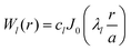
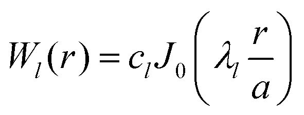
For the radial part, the solution of the harmonic case is assumed:
| |  | (10) |
Jk are the Bessel functions of the first kind of the
kth order and
cl are the normalization constants. The boundary conditions are given by the requirement that the deflection is zero at the edge:
This is fulfilled if the roots λl are given by:
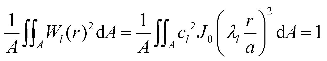
There exists an infinite number of roots and, thus, an infinite number of eigenfrequencies. The normalization constants cl are calculated via:
| |  | (13) |
The temporal parts
Zl(
t) are computed using
eqn (9) and (10) substituted in
eqn (8)| | 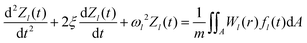 | (14) |
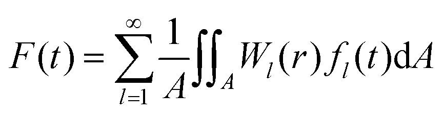
provided that the force
F is defined
via the normalized integral of the forces
fl(
t) of all vibrational modes:
| |  | (15) |
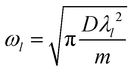
The eigenfrequencies
ωl are given by:
| |  | (16) |
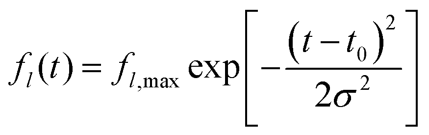
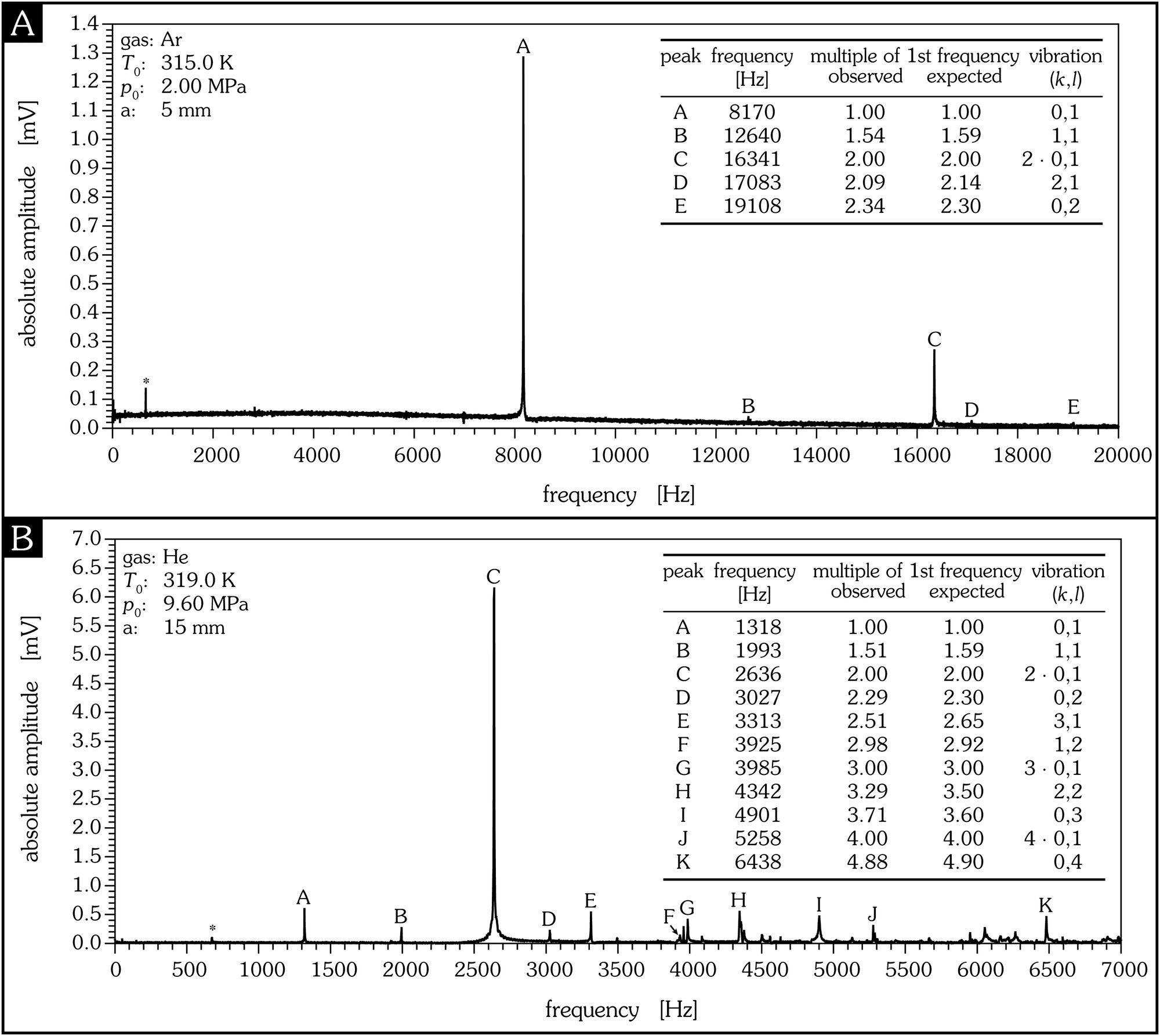
Therefore, the tension of the membrane can be accessed by determining the eigenfrequencies. In order to proof our assumptions (membrane vibration, consideration of axisymmetric vibration only) frequency spectra for different detector sizes are calculated from measured PVDF detector signals and shown in Fig. 10. Obviously, the observed vibration frequencies of the PVDF foil match the ratios expected from our model description rather well. It thus may be concluded that both assumptions are fulfilled for the detector with a sensitive radius of 5 mm. The frequency spectrum of the detector with a sensitive radius of 15 mm also shows interfering signals and many non-axisymmetric vibrations. If the supersonic jet is interrogated on the symmetry axis and at distances where particle–particle collisions have ceased, the one-dimensional Maxwell–Boltzmann velocity distribution is effectively indistinguishable from a shifted Gaussian distribution.25 Therefore, the time dependence of the applied force fl(t) of the lth mode is given by:
| | 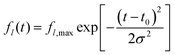 | (17) |
Here,
fl,max is the maximum applied force of the
lth mode,
t0 is the mean arrival time of the incoming particle pulse, and
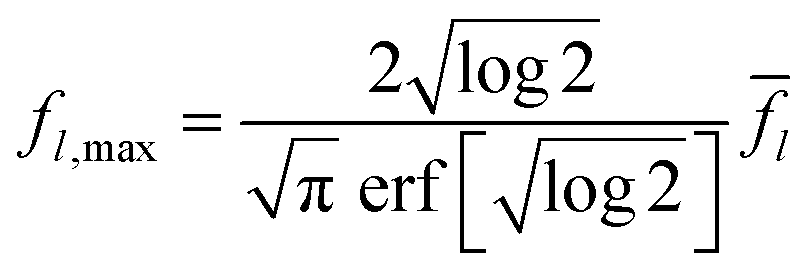
σ is a measure of the temporal width. The maximum applied force is related to the average force
![[f with combining macron]](https://www.rsc.org/images/entities/i_char_0066_0304.gif) l
l and can be determined by the full width at half maximum (FWHM):
| |  | (18) |
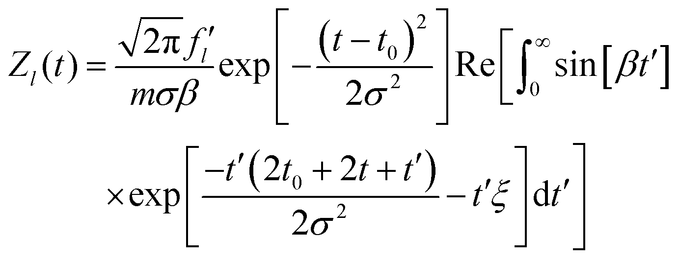
The time dependence of the axial displacement
Zl(
t) is given by
eqn (14) and can be calculated analytically: its solution is obtained by the Fourier transform of
eqn (14). The inverse Fourier transform results in:
| | 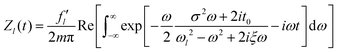 | (19) |
Here,
ω is an angular frequency and Re[
x] gives the real part of
x.

is given by:
| |  | (20) |
Eqn (19) can be rewritten as:
26| | 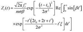 | (21) |
with

and a dummy integration variable
t′.
Eqn (21) can be evaluated by a computer algebra system such as Mathematica.
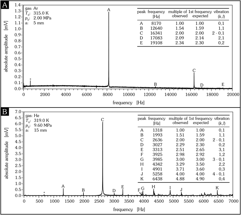 |
| | Fig. 10 Frequency spectra calculated from the measured time spectra for two different detector sizes. The good agreement between the experimental and theoretical values supports the applicability of the model assumptions. The theoretical multiplies of the frequency λl/λ1 for different k are calculated by the ratio of the roots given by Jk(λl). In the case of k = 0 the vibrations are axisymmetric, for k ≥ 1 the vibrations are non-axisymmetric. The uncertainty of the frequency determination can be estimated by a comparison with a known frequency such as the frequency of the turbo molecular pump (660 Hz, marked with an asterisk). From this, the uncertainty of the frequency is estimated to be in the range of ±2.3%. | |
| | f(t)dt = d(mpulse![[v with combining macron]](https://www.rsc.org/images/entities/i_char_0076_0304.gif) ) ) | (22) |
Here, the momentum mpulse is given by the mass of all impinging particles, mpulse, multiplied by the mean particle velocity, . The duration of the surface collision tFWHM is approximated by the FWHM of the impacting particle pulse. The integration of eqn (22) over time yields the time-average of the force :| | 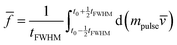 | (23) |
The momentum change depends on the change of the particle velocity, which can be described by the coefficient of restitution, κ, with 0 ≤ κ ≤ 1:| | 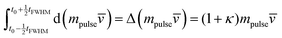 | (24) |
κ and thus depend on the gas–surface interaction with:| | 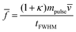 | (25) |
The mass of all impacting particles is related to the average particle density, ρpulse, seen by the detector| | | mpulse = ρpulsesFWHMA | (26) |
where sFWHM is the distance the particle jet travels in the time tFWHM:| | | sFWHM = tFWHM | (27) |
As already noted in Section A.1.2, the density is assumed to be constant over the detector area. Using eqn (22), (25) and (27), the mean force applied by impacting particles in a pulsed, supersonic molecular beam experiment is expressed by the momentum flux of the impacting particles and the sensitive detector area A:| | | = (1 + κ)ρpulse2A | (28) |
A.1.4 Generated current due to vibration.
The current generated by the displacement of the PVDF foil can be calculated using eqn (5) with the definitions of the strains, eqn (7), and the axial displacement w(r,t), which is given by eqn (9) and its solution according to eqn (10) and (21). Because the strain depends on the z-position, the average strain is calculated by integration of eqn (5) from w(r,t) to w(r,t) + h/2 and standardized by multiplication with 2/h. Because the axial displacement w(r,t) is small, the integration limit can be simplified to the range from 0 to h/2. The integration over half the thickness of the foil is due to the opposite charge generation: +q|z=h/2 and −q|z=−h/2.
A.2 Pyroelectric effect.
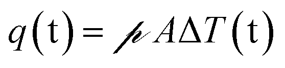
Pyroelectricity describes the ability of a material to generate surface charges due to a temperature change. Because of the inelastic particle–surface interaction the impacting particles transfer part of their kinetic energy to the PVDF foil, resulting in a temperature increase of the foil. The charge generated due to a temperature change is given by:| | 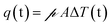 | (29) |
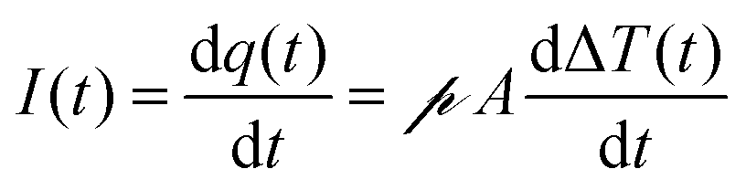
Here,  is the pyroelectric coefficient which describes the change of polarization with temperature per area and ΔT is the temperature difference between the foil and the ambient temperature. Thus, the generated current is given by:
| | 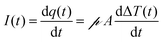 | (30) |
The increase in temperature caused by the power exerted by the supersonic molecular beam, P, is found by solving:27,28| | 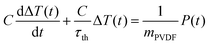 | (31) |
C is the heat capacity, τth the cooling rate, and mPVDF the mass of the PVDF foil.
This description involves the following assumptions:
• The pyroelectric area is of constant size. Because of vibrations due to impacting particles the area of the PVDF foil changes periodically. The axial displacement, however, is extremely small such that the change of area can be safely neglected. Also, a typical temperature increase is in the range of some millikelvin and, thus, thermal expansion of the foil is negligible, too.
• Because the particle distribution is assumed to be constant over the detector area, see Section A.1.2, the temperature change is considered to be independent of the foil coordinates, i.e., eqn (31) describes the temperature change of the entire foil and does not depend on the radial coordinate nor on the foil thickness.
• The cooling term in eqn (31) is caused mainly by the heat loss due to radiation and the thermal conductivity between the PVDF foil and its mechanical mount. Because the experiments are conducted in vacuum the heat loss caused by convection is negligible. The cooling term is approximated to be linear to the temperature change.
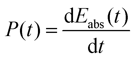
The power exerted by the supersonic jet is given by the absorbed energy per time:
| |  | (32) |
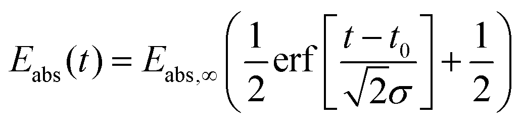
The time dependence of this absorbed energy, which is approximated to be Gaussian, can be expressed by
| |  | (33) |
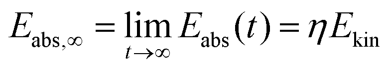
The total adsorbed energy
Eabs,∞ can be calculated by the limit of
Eabs(
t) as
t approaches infinity
| | 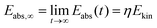 | (34) |
where
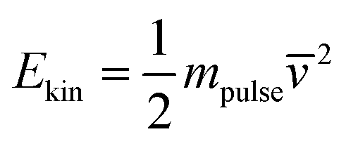
η is the coefficient of energy accommodation. The kinetic energy is given by:
| |  | (35) |
The parameters of the temporal width
σ and the time delay
t0 are the same as for the piezoelectric case.
B Comparison of the piezo- and pyroelectric effect
B.1 Superposition of both effects.
Both the pyroelectric and the piezoelectric effect generate surface charges. If these effects are assumed to be independent, the amount of generated charges Qtotal and its temporal dependence, Itotal, are given by both contributions.
According to the simplified circuit, see Fig. 4, the output voltage of a transimpedance amplifier is given by:
Here,
U is the output voltage of the amplifier,
GTA the gain of the transimpedance amplifier, and
Itotal the total current resulting from the sum of the piezoelectric and the pyroelectric effect.
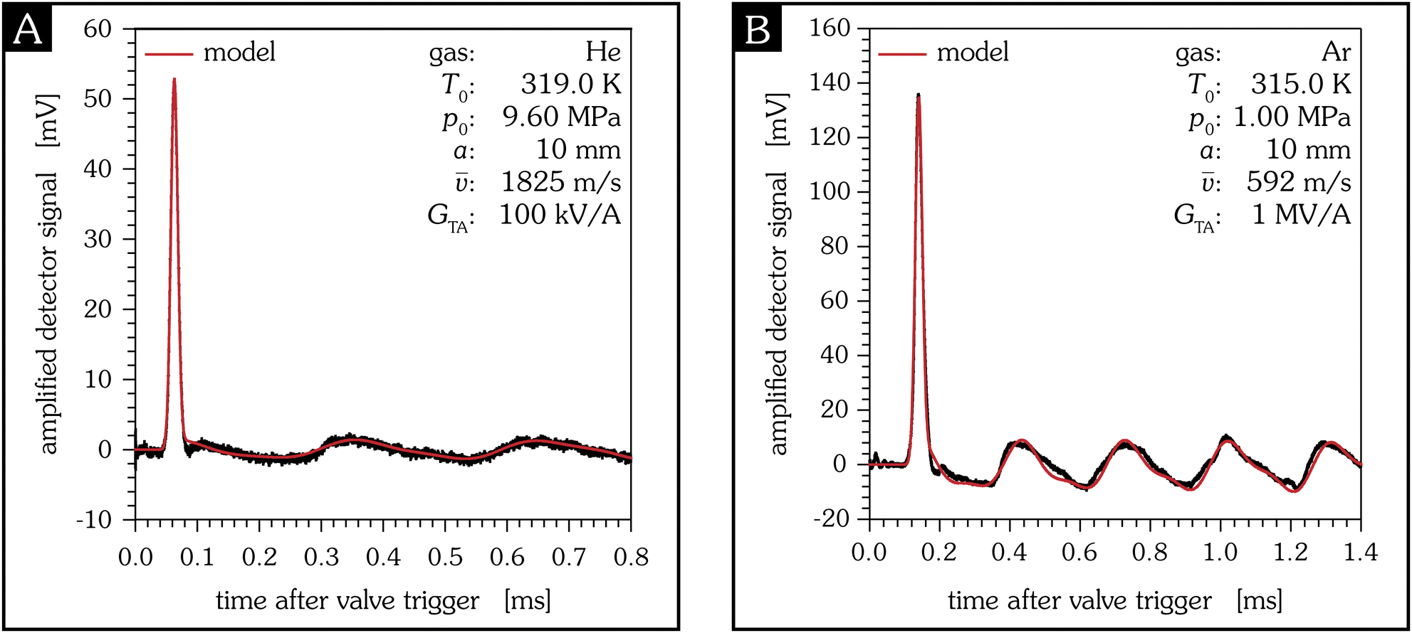
Fig. 11 shows two signals of He and Ar which are fitted with the presented model. The material parameters are given in the manual of the PVDF foil and are summarized in
Table 1. The two main eigenfrequencies are determined by additional measurements
via FFT. The fit parameters are the two amplitudes of the eigenfrequencies
f1,max and
f2,max, the total absorbed energy
Eabs,∞, the temporal width
σ, and the shift parameter
t0 of the Gaussian distribution. For the considered time window in
Fig. 11 the cooling term turns out to be irrelevant. The fit results are summarized in
Table 2.
 |
| | Fig. 11 Fitted signals of the supersonic molecular beam detector for He (A) and Ar (B) pulses, measured with an transimpedance amplifier. The fit according to the presented model yields a coefficient of energy accommodation of 0.0035 ± 0.0005 for He (A) and 0.0090 ± 0.0004 for Ar (B). | |
Table 1 Material parameters of the used PVDF foil at 23 °C29
| Parameter |
Description |
Value |
|
d
31
|
Piezoelectric constant |
8.5 pCN−1 |
|
d
32
|
Piezoelectric constant |
8.5 pCN−1 |
|
d
33
|
Piezoelectric constant |
−16.5 pCN−1 |

|
Pyroelectric constant |
−26 × 10−4 μC K−1 m−1 |
|
a
|
Radius |
5 mm, 10 mm and 15 mm |
|
h
|
Thickness |
25 μm |
|
C
|
Specific heat capacity |
1200 J K−1 kg−1 |
|
ρ
|
Density |
1780 kg m−3 |
|
Y
|
Young's modulus |
2.5 GPa |
|
μ
|
Possion's ratio |
0.35 |
Table 2 Summary of the fit results of the measurements depicted in Fig. 11. The average force is given by sum of the two amplitudes of the eigenfrequencies f1,max and f2,max. Both eigenfrequencies are time averaged according to eqn (18)
| Gas |
Parameter |
Fit result |
| He – Fig. 11A |
E
abs,∞
|
157.1 nJ |
|
|
70.35 mN |
|
σ
|
5.6 μs |
|
t
0
|
63.2 μs |
| Ar – Fig. 11B |
E
abs,∞
|
67.2 nJ |
|
|
28.17 mN |
|
σ
|
10.1 μs |
|
t
0
|
140.3 μs |
B.2 Comparison of the induced pyro- and piezoelectric effect.
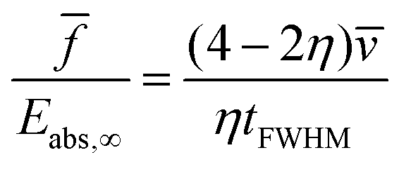
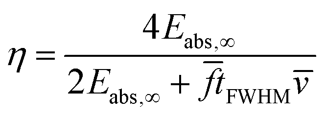
A pulse of particles colliding with a solid surface at a certain velocity always exerts a force on the surface. The energy transfer depends on the coefficients of restitution and energy accommodation. They are correlated by:The ratio of the applied force and the absorbed energy is given by eqn (28), (34), (35) and (37):| | 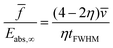 | (38) |
Therefore, the coefficient of energy accommodation can be calculated by a comparison of the contributions of those two effects, provided that the mean velocity of the impacting particles is known:| | 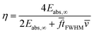 | (39) |
In the case of the fitted signals shown in Fig. 11, the coefficients of energy accommodation η are 0.0035 ± 0.0005 for He and 0.0090 ± 0.0004 for Ar. The source of the uncertainty is provided by the material parameters and the experimentally determined velocity.
Acknowledgements
Paul Saftien acknowledges support by the International Max Planck Research School (IMPRS) for Elementary Processes in Physical Chemistry. Wolfgang Christen gratefully acknowledges a Researcher Excellence Grant by the European Metrology Research Program (EMRP) “Energy and Environment”. The EMRP is jointly funded by the EMRP participating countries within EURAMET and the European Union.
Notes and references
-
D. Bassi, in Atomic and Molecular Beam Methods, ed. G. Scoles, Springer, New York, 1988, ch. 6, p. 153 Search PubMed.
-
M. Zen, in Atomic and Molecular Beam Methods, ed. G. Scoles, Springer, New York, 1988, ch. 10 Search PubMed.
- J. G. Choi, J. S. Hayden, M. T. O’Connor and G. J. Diebold, J. Appl. Phys., 1981, 52, 6016–6020 CrossRef CAS.
-
G. Scoles, Atomic and Molecular Beam Methods, Oxford University Press, New York, 1988 Search PubMed.
-
H. Pauly, Atom, Molecule, and Cluster Beams, Springer, New York, 2000 Search PubMed.
-
R. Campargue, Atomic and Molecular Beams, Springer, New York, 2001 Search PubMed.
- W. Christen and K. Rademann, Rev. Sci. Instrum., 2006, 77, 015109 CrossRef.
- W. Christen, T. Krause, B. Kobin and K. Rademann, J. Phys. Chem. A, 2011, 115, 6997 CrossRef CAS PubMed.
- W. Christen, J. Chem. Phys., 2013, 139, 024202 CrossRef PubMed.
- U. Even, J. Jortner, D. Noy, N. Lavie and C. Cossart-Magos, J. Chem. Phys., 2000, 112, 8068–8071 CrossRef CAS.
- W. Christen, J. Chem. Phys., 2013, 139, 154202 CrossRef PubMed.
- A. Holmes-Siedle, P. Wilson and A. Verrall, Mater. Des., 1983, 4, 910–918 CrossRef.
- L. Li, M. Zhang, M. Rong and W. Ruan, RSC Adv., 2014, 4, 3938–3943 RSC.
- G. T. Davis, J. E. McKinney, M. G. Broadhurst and S. C. Roth, J. Appl. Phys., 1978, 49, 4998–5002 CrossRef CAS.
-
J. W. Dally, W. F. Riley and K. G. McConnell, Instrumentation for engineering measurements, John Wiley & Sons, 2nd edn, 1993 Search PubMed.
- J. A. Main, D. V. Newton, L. Massengill and E. Garcia, Smart Mater. Struct., 1996, 5, 766–775 CrossRef CAS.
- W. Q. Liu, Z. H. Feng, R. B. Liu and J. Zhang, Rev. Sci. Instrum., 2007, 78, 125107 CrossRef CAS PubMed.
- M. Simhony and A. Shaulov, J. Appl. Phys., 1971, 42, 3741–3744 CrossRef CAS.
- H. C. W. Beijerinck and N. F. Verster, Physica B+C, 1981, 111, 327–352 CrossRef CAS.
- T. Reisinger, G. Bracco, S. Rehbein, G. Schmahl, W. E. Ernst and B. Holst, J. Phys. Chem. A, 2007, 111, 12620–12628 CrossRef CAS PubMed.
- N. G. Korobeishchikov, M. A. Roenko and G. I. Tarantsev, J. Cluster Sci., 2017, 28, 2529–2547 CrossRef CAS.
- H. A. Sodano, G. Park and D. J. Inman, Strain, 2004, 40, 49–58 CrossRef.
- Y. Sun and H. Tohmyoh, J. Sound Vib., 2009, 319, 392–405 CrossRef.
-
S. S. Rao, Vibration of Continuous Systems, Wiley, 2nd edn, 2019, ch. 13 Search PubMed.
- W. Christen, K. Rademann and U. Even, J. Phys. Chem. A, 2010, 114, 11189–11201 CrossRef CAS PubMed.
- J. G. Choi and G. J. Diebold, Chem. Phys., 1982, 73, 19–25 CrossRef CAS.
- S. G. Porter, Ferroelectrics, 1981, 33, 193–206 CrossRef CAS.
- J. Stuckless, N. Frei and C. T. Campbell, Sens. Actuators, B, 2000, 62, 13–22 CrossRef CAS.
-
Solef® PVDF – Design & Processing Guide, https://www.solvay.com.
|
| This journal is © the Owner Societies 2024 |
Click here to see how this site uses Cookies. View our privacy policy here. 
 Open Access Article
 This Open Access Article is licensed under a
  *a
*a

 , the coupling coefficients e, and the permittivity ε. The superscripts indicate the conditions held constant during measurement.
 . Because only very small deflections occur, e.g., in Fig. 11 less than 35 μm for He and less than 20 μm for Ar, anisotropy is neglected and the stiffness coefficients
  of an isotropic material are used and expressed by Young's modulus Y and Possion's ratio μ:
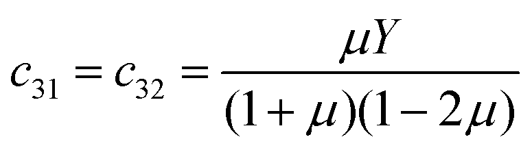


 is given by:
 and a dummy integration variable t′. Eqn (21) can be evaluated by a computer algebra system such as Mathematica.

 is the pyroelectric coefficient which describes the change of polarization with temperature per area and ΔT is the temperature difference between the foil and the ambient temperature. Thus, the generated current is given by: