A weakly ion pairing electrolyte designed for high voltage magnesium batteries†
Chang
Li
 ab,
Rishabh D.
Guha
c,
Abhinandan
Shyamsunder
ab,
Kristin A.
Persson
*bde and
Linda F.
Nazar
ab,
Rishabh D.
Guha
c,
Abhinandan
Shyamsunder
ab,
Kristin A.
Persson
*bde and
Linda F.
Nazar
 *ab
*ab
aDepartment of Chemistry and the Waterloo Institute for Nanotechnology, University of Waterloo, Ontario N2L 3G1, Canada. E-mail: lfnazar@uwaterloo.ca
bJoint Center for Energy Storage Research, Argonne National Laboratory, Lemont, Illinois 60439, USA
cMaterials Science Division, Lawrence Berkeley National Laboratory, Berkeley, California 94720, USA
dMolecular Foundry, Lawrence Berkeley National Laboratory, 1 Cyclotron Road, Berkeley, California 94720, USA. E-mail: kristinpersson@berkeley.edu
eDepartment of Materials Science and Engineering, UC Berkeley, Berkeley, California 94720, USA
First published on 16th November 2023
Abstract
High-voltage rechargeable magnesium batteries (RMBs) are potential alternatives to lithium-ion batteries owing to the low cost and high abundance of magnesium. However, the parasitic reactions of the latter with many electrolytes greatly hinders the stability and kinetics of Mg plating/stripping. Here we report a new and easily accessible solvent-designed electrolyte, which effectively solves the difficulty of ion pair dissociation and facilitates fast nanoscale Mg nucleation/growth using simple Mg(TFSI)2 as the salt, enabling a facile interfacial charge transfer process. Dendrite-free Mg plating/stripping is maintained for over 7000 hours (∼10 months) at a practical areal capacity of 2 mA h cm−2. The high-voltage stability of these electrolytes is demonstrated by benchmarking with polyaniline||Mg full cells with an operating voltage up to 3.5 V that exhibit stable cycling at a 2C rate with 99% coulombic efficiency after 400 cycles. This work opens up new frontiers in coupling low-cost electrolytes with next-generation high-voltage cathode materials for fast-charging RMBs with long life and high energy densities.
Broader contextNet-zero carbon dioxide emission demands clean renewable energy, while harnessing it requires electrochemical storage devices with high energy density, safety and affordability. Rechargeable magnesium batteries (RMBs) are candidates because of the abundance of Mg (over 1000 times that of Li), the high theoretical volumetric energy density of Mg metal, and magnesium's low reduction potential. However, to date, there is no practical RMB on the market owing to many unsolved major challenges. The key factors can be partly addressed by designing better electrolytes. Here, we report a new concept for an electrolyte system that disrupts strong ion-pairing in solution, enabling highly reversible, high-voltage Mg metal batteries. This electrolyte relies on two key components: ethyl phosphate as a high dielectric solvent to unlock the activity of Mg2+/Mg redox, and co-ether solvents to improve the kinetics and stability of Mg plating/stripping. The complex interactions between cation, anion and solvent are revealed by advanced spectroscopies and MD simulations, providing new design principles. The use of cost-effective and commercially available Mg salts simplifies scalability. The 4 V stability of this electrolyte is demonstrated by benchmarking Mg metal batteries assembled with an organic polymer cathode that run at a 2C rate for over 400 cycles with 99% coulombic efficiency up to 3.5 V. Our design opens up new frontiers for low-cost and high-voltage electrolyte approaches that take advantage of facile desolvation processes at the interfaces, and can establish a platform for new avenues of investigation for next generation energy storage in RMBs. |
Introduction
Net-zero carbon dioxide emission demands clean renewable energy, while harnessing it requires electrochemical storage devices with high energy density, safety and affordability.1–3 To achieve decarbonization, much effort is being devoted to new battery technologies beyond lithium-ion batteries (LIBs).2,4 Rechargeable magnesium batteries (RMBs) stand out because of the abundance of Mg (over 1000 times that of Li),5 the high theoretical volumetric energy density of a Mg metal anode (3833 mA h cm−3vs. 2046 mA h cm−3 of Li),6 and magnesium's relatively low reduction potential −2.38 V versus the standard hydrogen electrode (SHE)). Although Mg dendrite formation was confirmed in some studies,7,8 generally Mg is thought to be less prone to this phenomenon1 than Li,9 and suggests RMBs can potentially be safer electrochemical energy devices than lithium metal batteries.10Among many unaddressed challenges for practical RMBs, designing better electrolytes is one key to their successful commercialization.1,4,5,11 The charge-dense Mg2+ cation results in: (1) a high desolvation penalty due to the slow kinetics of ion pair dissociation; and (2) very slow ion migration kinetics because of a thick solid electrolyte interface (SEI) on the Mg surface which impedes the interfacial charge transfer process.1,12 Therefore, transferring electrolyte design principles from LIBs directly to RMBs is not possible. Utilizing conventional carbonate-based solvents and fluorinated anions such as BF4− and PF6− results in tightly bonded contact ion pairs (CIPs) that aggravate passivation of the Mg anode via pronounced electrolyte decomposition.12 Classical Mg electrolytes rely on concentrated chloride species to unlock reversible Mg plating/stripping;13 however, the latter are oxidatively unstable (∼2.5 V vs. Mg2+/Mg) and highly corrosive to current collectors or battery casings.1 Their dominant intercalation species – MgxCly+ – also lowers the energy density compared to Mg2+ storage.11,14
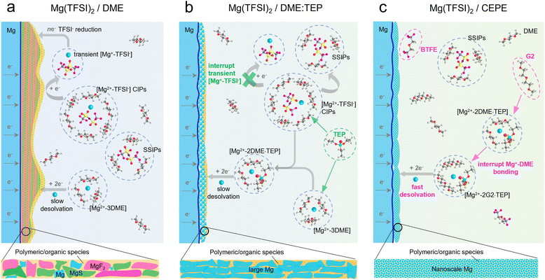
To tackle these challenges, halide-free Mg salts with bulky alkoxyborate/aluminate or carborane anions were developed that show high reversibility for Mg plating/stripping with over 99% coulombic efficiency (CE) and oxidative stability over 3.5 V vs. Mg2+/Mg.15–19 Among these, Mg(CB11H12)2 in a 1,2-dimethoxyethane (DME)/diglyme (G2) solvent blend exhibits very fast Mg plating/stripping, and can support 5C-rate cycling with pyrene-4,5,9,10-tetraone (PTO) as the enolization cathode.20 The discovery of such bulky anion-salts dates back three decades.12,21 Unfortunately, most are expensive due to the reagents needed for their complex synthesis and purification procedures, where trace impurities can cause short lifetimes for Mg plating/stripping.11,16,22–24 A more economical option relies on modifying Mg electrolytes and using commercial halide-free salts such as magnesium bis(trifluoromethanesulfonimide) (Mg(TFSI)2 with high oxidative stability (approaching 4 V vs. Mg2+/Mg) and good ionic conductivity (1–6 mS cm−1).25–27 However, unlike bulky alkoxyborates/aluminates and carborane anions that prefer to exist as solvent-separated ion pairs (SSIPs) in ether-type solvents, the more electron localized TFSI− anion contributes to large fractions of CIPs that are easily reduced during Mg plating (Scheme 1(a)).28–31 The resulting inorganic products (for example, MgF2 and MgS), together with other solvent-derived polymeric/organic species,32 lead to a thick impedance layer on the Mg surface that passivates Mg2+/Mg charge transfer. Currently, only a few studies have shown reversible Mg plating/stripping in such electrolytes. Impressively, additives with high donor numbers – methoxyethylamines – that tightly coordinate with Mg2+ can suppress DME decomposition and enable efficient Mg plating/stripping with over 99.5% CE over 100 cycles.33 Similarly, trimethyl phosphate was utilized to suppress DME decomposition.34,35 However, TFSI− anion decomposition occurs in the latter, leading to a lifetime of ∼450 hours in symmetric cells at a current density of 0.1 mA cm−2.34,35 Nonetheless, the phosphate approach inspired us to design solvents to boost Mg anode stability.
Here, we invent a new co-ether phosphate electrolyte (CEPE) system that enables fast and highly stable Mg2+/Mg redox activity at the anode and facile anion storage chemistry at the cathode using commercial Mg(TFSI)2 as the salt. A family of methyl phosphates ((CH3)3(CH2)nPO4, n = 0–4) with high dielectric constants and donor numbers were selected as electrolyte additives to interrupt [Mg2+–TFSI−] CIPs (Scheme 1(b)). This results in suppressed TFSI− reduction, which limits the thickness of the passivation layer and greatly lowers the voltage hysteresis for Mg plating/stripping. To further improve the Mg anode reversibility and stability, different ethers were chosen as co-solvents to tune the Mg2+ solvation sheath, thus facilitating desolvation and nanoscale Mg nucleation/growth (Scheme 1(c)). By combining advanced spectroscopy techniques, molecular dynamics (MD) simulations, and density-functional-theory (DFT) calculations, the Mg2+ solvation structure and its interaction with anions or solvents are disclosed in depth. The optimized CEPE electrolytes sustain highly reversible Mg plating/stripping behavior at a range of current densities. We demonstrate ultra-stable Mg plating/stripping for over 7000 hours (9.7 months) at a practical current density of 2 mA cm−2 and an areal capacity of 2 mA h cm−2. Importantly, the > 4 V anodic stability of these electrolytes enables polyaniline||Mg full cells to perform up to 3.5 V for over 400 cycles at a fast 2C rate with excellent capacity retention.
Results and discussion
Highly reversible and stable Mg plating/stripping in CEPE
We considered three electrolytes to evaluate their Mg plating/stripping behavior (see Methods and Table S1, ESI†): (1) 0.4 M Mg(TFSI)2/DME as the baseline electrolyte; (2) 0.4 M Mg(TFSI)2/DME![[thin space (1/6-em)]](https://www.rsc.org/images/entities/char_2009.gif) :
:![[thin space (1/6-em)]](https://www.rsc.org/images/entities/char_2009.gif) triethyl phosphate (TEP) [10
triethyl phosphate (TEP) [10![[thin space (1/6-em)]](https://www.rsc.org/images/entities/char_2009.gif) :
:![[thin space (1/6-em)]](https://www.rsc.org/images/entities/char_2009.gif) 1 in vol, denoted as Mg(TFSI)2/DME:TEP]; and (3) tailor-designed Mg(TFSI)2/CEPE [0.4 M Mg(TFSI)2/DME
1 in vol, denoted as Mg(TFSI)2/DME:TEP]; and (3) tailor-designed Mg(TFSI)2/CEPE [0.4 M Mg(TFSI)2/DME![[thin space (1/6-em)]](https://www.rsc.org/images/entities/char_2009.gif) :
:![[thin space (1/6-em)]](https://www.rsc.org/images/entities/char_2009.gif) diethylene glycol dimethyl ether (G2)
diethylene glycol dimethyl ether (G2)![[thin space (1/6-em)]](https://www.rsc.org/images/entities/char_2009.gif) :
:![[thin space (1/6-em)]](https://www.rsc.org/images/entities/char_2009.gif) bis(2,2,2-trifluoroethyl) ether (BTFE)
bis(2,2,2-trifluoroethyl) ether (BTFE)![[thin space (1/6-em)]](https://www.rsc.org/images/entities/char_2009.gif) :
:![[thin space (1/6-em)]](https://www.rsc.org/images/entities/char_2009.gif) TEP, 19
TEP, 19![[thin space (1/6-em)]](https://www.rsc.org/images/entities/char_2009.gif) :
:![[thin space (1/6-em)]](https://www.rsc.org/images/entities/char_2009.gif) 19
19![[thin space (1/6-em)]](https://www.rsc.org/images/entities/char_2009.gif) :
:![[thin space (1/6-em)]](https://www.rsc.org/images/entities/char_2009.gif) 2
2![[thin space (1/6-em)]](https://www.rsc.org/images/entities/char_2009.gif) :
:![[thin space (1/6-em)]](https://www.rsc.org/images/entities/char_2009.gif) 4 in vol]. The molar ratio of Mg2+
4 in vol]. The molar ratio of Mg2+![[thin space (1/6-em)]](https://www.rsc.org/images/entities/char_2009.gif) :
:![[thin space (1/6-em)]](https://www.rsc.org/images/entities/char_2009.gif) TEP in the latter two electrolytes is ∼1
TEP in the latter two electrolytes is ∼1![[thin space (1/6-em)]](https://www.rsc.org/images/entities/char_2009.gif) :
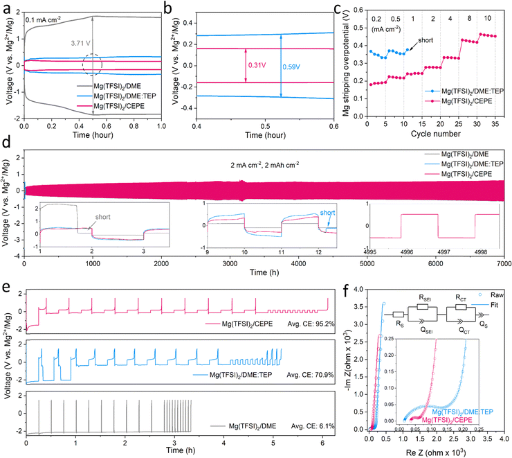
:![[thin space (1/6-em)]](https://www.rsc.org/images/entities/char_2009.gif) 1. Instead of alkoxyborate/aluminate or carborane-based Mg salts, commercially available Mg(TFSI)2 was chosen as the salt, both on the basis of cost and owing to its strong ion pairing in ether-type electrolytes which we sought to disrupt with electrolyte design. TEP was chosen as a stronger donor (coordinating) solvent than glyme, while BTFE is a non-coordinating solvent. These choices of salt and solvents give us a good platform to understand the effect of cation/anion-solvent interaction on interfacial charge transfer in Mg plating/stripping. The optimal solvent ratios were determined through multiple experiment trials (Fig. S1, ESI†). Fig. 1(a) and (b) shows the voltage profiles of these electrolytes in Mg||Mg symmetric cells at a current density of 0.1 mA cm−2. In Mg(TFSI)2/CEPE, a very low Mg plating/stripping overpotential of ∼0.15 V was obtained – nearly two-fold lower than in Mg(TFSI)2/DME:TEP (∼0.3 V) – whereas in Mg(TFSI)2/DME more than a magnitude higher overpotential of ∼1.85 V was observed. The superiority of Mg(TFSI)2/CEPE was further confirmed by the fast-kinetics of Mg plating/stripping at different current densities (Fig. 1(c) and Fig. S2, ESI†), which reveals a low Mg plating/stripping overpotential of <0.5 V even at 10 mA cm−2. In contrast, the cell with Mg(TFSI)2/DME:TEP quickly shorted at 1 m A cm−2 (Fig. 1(c) and Fig. S1, ESI†) and Mg(TFSI)2/DME shows a continuously high overpotential up to ∼3.5 V (Fig. S3, ESI†).
1. Instead of alkoxyborate/aluminate or carborane-based Mg salts, commercially available Mg(TFSI)2 was chosen as the salt, both on the basis of cost and owing to its strong ion pairing in ether-type electrolytes which we sought to disrupt with electrolyte design. TEP was chosen as a stronger donor (coordinating) solvent than glyme, while BTFE is a non-coordinating solvent. These choices of salt and solvents give us a good platform to understand the effect of cation/anion-solvent interaction on interfacial charge transfer in Mg plating/stripping. The optimal solvent ratios were determined through multiple experiment trials (Fig. S1, ESI†). Fig. 1(a) and (b) shows the voltage profiles of these electrolytes in Mg||Mg symmetric cells at a current density of 0.1 mA cm−2. In Mg(TFSI)2/CEPE, a very low Mg plating/stripping overpotential of ∼0.15 V was obtained – nearly two-fold lower than in Mg(TFSI)2/DME:TEP (∼0.3 V) – whereas in Mg(TFSI)2/DME more than a magnitude higher overpotential of ∼1.85 V was observed. The superiority of Mg(TFSI)2/CEPE was further confirmed by the fast-kinetics of Mg plating/stripping at different current densities (Fig. 1(c) and Fig. S2, ESI†), which reveals a low Mg plating/stripping overpotential of <0.5 V even at 10 mA cm−2. In contrast, the cell with Mg(TFSI)2/DME:TEP quickly shorted at 1 m A cm−2 (Fig. 1(c) and Fig. S1, ESI†) and Mg(TFSI)2/DME shows a continuously high overpotential up to ∼3.5 V (Fig. S3, ESI†).
While we observe improved Mg reversibility with TEP, the stability of the Mg anode during long-term cycling is of even greater importance.12,32,34,35 We investigated Mg||Mg symmetric cell behaviour in different electrolytes. At a practical current density of 2 mA cm−2 and areal capacity of 2 mA h cm−2 (Fig. 1(d)), cells with Mg(TFSI)2/DME and Mg(TFSI)2/DME:TEP undergo rapid short circuiting after only 2 and 12 hours, respectively. In contrast, cells employing Mg(TFSI)2/CEPE undergo robust stripping/plating for over 7000 hours (9.7 months) without significant increase in voltage hysteresis, and exhibit a total cumulative capacity of over 14 A h cm−2. The overpotential of Mg plating/stripping stabilizes at around 500 mV with no sudden voltage drops, ruling out the possibility of (soft) short circuits, as also confirmed by a charge transfer resistance of about 400 Ω attained after 7000 hours (Fig. S4, ESI†). To the best of our knowledge, this represents unprecedented stability and performance of Mg plating/stripping under such demanding conditions (Table S2, ESI†), suggesting good promise for long-life practical RMBs. The coulombic efficiency (CE) of Mg plating/stripping was investigated using Mg||Au asymmetric cells by a modified Aurbach method reported by Zhang et al.20,36 The highest CE of 95.2% was achieved in Mg(TFSI)2/CEPE (Fig. 1(e)), which is significantly greater that of Mg(TFSI)2/DME:TEP (70.9%). Therefore, the cumulative irreversible capacity over 7000 hours of plating/stripping (3500 cycles, Fig. 3(d)) in the CEPE electrolyte is only 2.4% of its total cumulative capacity. The baseline Mg(TFSI)2/DME electrolyte, in contrast, shows very limited Mg plating/stripping reversibility with only 6.1% CE due to pronounced electrolyte decomposition. While the increase in CE from DME/TEP to CEPE is remarkable, the latter's CE is not quite as high as achieved in bulky-anion salt alkoxyborate/aluminate16–18 or carborane-based electrolytes.15,20 This is probably due to the persistence of a low fraction of [Mg2+–TFSI−] contact-ion pairs (despite the major disruption of their formation, see discussion below), which are more easily reduced on the Mg surface.28
The charge transfer process at the Mg/electrolyte interface was further explored by electrochemical impedance spectroscopy (EIS) studies (Fig. 1(f)). In Mg(TFSI)2/CEPE, a very low charge transfer resistance (RCT) was observed in a Mg||Mg symmetric cell, consistent with its superior rate performance. On the other hand, Mg(TFSI)2/DME:TEP, despite exhibiting the highest ionic conductivity of 6.4 mS cm−1 among the three electrolytes (Fig. S5, ESI†), shows significantly higher RCT than Mg(TFSI)2/CEPE. This suggests interfacial electrochemistry plays a dominant role during Mg plating/stripping. Indeed, diffusion-limited tails ascribed to ion diffusion via as-formed interfacial Mg2+-conducting SEIs37 were observed in the low-frequency region in both electrolytes. In Mg(TFSI)2/DME, however, the very large charge transfer resistance is similar to that of many previous reports (Fig. S6, ESI†).15,27,34 This is due to electrolyte decomposition on the Mg surface that forms an interfacial (Mg2+-insulating) passivation layer, which leads to the absence of a diffusion-limited tail.
Minimized anion activity by phosphates
The role of TEP in CEPE was systematically explored by controlling the DME![[thin space (1/6-em)]](https://www.rsc.org/images/entities/char_2009.gif) :
:![[thin space (1/6-em)]](https://www.rsc.org/images/entities/char_2009.gif) TEP ratio, which is directly correlated to Mg2+/Mg redox activity. Fig. 2(a) shows the Mg plating curves of the initial five cycles of Mg||Mg symmetric cells with different DME
TEP ratio, which is directly correlated to Mg2+/Mg redox activity. Fig. 2(a) shows the Mg plating curves of the initial five cycles of Mg||Mg symmetric cells with different DME![[thin space (1/6-em)]](https://www.rsc.org/images/entities/char_2009.gif) :
:![[thin space (1/6-em)]](https://www.rsc.org/images/entities/char_2009.gif) TEP ratios. The Mg plating overpotential shows a TEP concentration-dependent behavior, identifying a DME
TEP ratios. The Mg plating overpotential shows a TEP concentration-dependent behavior, identifying a DME![[thin space (1/6-em)]](https://www.rsc.org/images/entities/char_2009.gif) :
:![[thin space (1/6-em)]](https://www.rsc.org/images/entities/char_2009.gif) TEP ratio of 50
TEP ratio of 50![[thin space (1/6-em)]](https://www.rsc.org/images/entities/char_2009.gif) :
:![[thin space (1/6-em)]](https://www.rsc.org/images/entities/char_2009.gif) 3 as an effective “sweet” spot to unlock fast Mg plating/stripping, and corresponding to a Mg2+
3 as an effective “sweet” spot to unlock fast Mg plating/stripping, and corresponding to a Mg2+![[thin space (1/6-em)]](https://www.rsc.org/images/entities/char_2009.gif) :
:![[thin space (1/6-em)]](https://www.rsc.org/images/entities/char_2009.gif) TEP molar ratio of 10
TEP molar ratio of 10![[thin space (1/6-em)]](https://www.rsc.org/images/entities/char_2009.gif) :
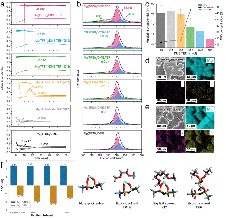
:![[thin space (1/6-em)]](https://www.rsc.org/images/entities/char_2009.gif) 7. This is directly correlated to the CIP fraction in the electrolytes, as revealed by fitting Raman spectra of the TFSI− band in the 700–770 cm−1 region based on a well-established theory of SSIPs and CIPs (Fig. 2(b)).9,32,38 An abrupt decrease in CIP fraction from 40% to <30% is observed in DME
7. This is directly correlated to the CIP fraction in the electrolytes, as revealed by fitting Raman spectra of the TFSI− band in the 700–770 cm−1 region based on a well-established theory of SSIPs and CIPs (Fig. 2(b)).9,32,38 An abrupt decrease in CIP fraction from 40% to <30% is observed in DME![[thin space (1/6-em)]](https://www.rsc.org/images/entities/char_2009.gif) :
:![[thin space (1/6-em)]](https://www.rsc.org/images/entities/char_2009.gif) TEP (50
TEP (50![[thin space (1/6-em)]](https://www.rsc.org/images/entities/char_2009.gif) :
:![[thin space (1/6-em)]](https://www.rsc.org/images/entities/char_2009.gif) 3), matching the sharp drop in plating overpotential to −0.32 V (Fig. 2(c)). It indicates a threshold in CIP fraction where facile Mg2+/Mg redox activity is unlocked below that limit, and Mg2+ desolvation from coordinated solvents at the interface starts to play a critical role (see below). Indeed, previous studies report that significant reduction of CIPs at the Mg surface suppresses TFSI− activity.28,29 This is verified by the remarkable decrease of F/S signals from decomposed TFSI− in the energy-dispersive X-ray spectra (EDX, Fig. 2(d)) of Mg(TFSI)2/DME:TEP, in contrast to the strong F/S signals in Mg(TFSI)2/DME (Fig. 2(e)).
3), matching the sharp drop in plating overpotential to −0.32 V (Fig. 2(c)). It indicates a threshold in CIP fraction where facile Mg2+/Mg redox activity is unlocked below that limit, and Mg2+ desolvation from coordinated solvents at the interface starts to play a critical role (see below). Indeed, previous studies report that significant reduction of CIPs at the Mg surface suppresses TFSI− activity.28,29 This is verified by the remarkable decrease of F/S signals from decomposed TFSI− in the energy-dispersive X-ray spectra (EDX, Fig. 2(d)) of Mg(TFSI)2/DME:TEP, in contrast to the strong F/S signals in Mg(TFSI)2/DME (Fig. 2(e)).
To reveal the functionality of TEP in suppressing anion reduction activity, density-functional-theory (DFT) calculations were performed. In an implicit solvent, thermodynamically endergonic C–S bond dissociation was observed in the [Mg2+–TFSI−] CIPs (bond dissociation energy (BDE): 2.37 eV, Fig. 2(f)), whereas partially reduced transient [Mg+–TFSI−] CIPs show exergonic C–S bond dissociation (BDE: −1.25 eV), consistent with previous studies.28 The C–S bond dissociation accompanies complete reduction of Mg+ to Mg0 (Fig. S7, ESI†) and essentially enables an irreversible plating process. More exergonic C–S bond cleavage was obtained for [Mg+–TFSI−] CIPs surrounded by one explicit DME (BDE: −1.97 eV) or G2 molecule (BDE: −2.21 eV), emphasizing the co-solvation during charge transfer does not protect the TFSI− anions from reduction. The BDE is also exergonic (−1.51 eV) for a transient CIP surrounded by an explicit TEP molecule. In the molecular dynamics (MD) results (see Fig. 3(b) below), the paired Mg fraction decreases by ∼50% in the CEPE system when compared to the Mg(TFSI)2:DME system. These results, in conjunction with the Raman spectra (Fig. 2(b)), confirm that the introduction of TEP successfully outcompetes the TFSI− anions in the first solvation shell and significantly reduces the CIP concentration. Nonetheless, it is not reduced to zero. While the residual CIPs in CEPE could still induce limited anion decomposition, this may be further inhibited by applying interfacial protective coatings on the Mg surface,39 or by additional electrolyte design that is beyond the scope of this work.
Similar effects on activating reversible Mg2+/Mg redox in single DME solvents extends to other phosphates with a formula of (CH3)3(CH2)nPO4 (n = 0–4, Fig. S8, ESI†). The co-ether engineering approach functions similarly (for example, TMP with n = 0), albeit with poorer rate characteristics relative to TEP (Fig. S9 and S10, ESI†). Nonetheless, these phosphates with different numbers of methylene groups can behave very differently. Previous reports indicate TMP primarily displaces one DME from the Mg2+ solvation structure to suppress DME reduction by forming TMP-reduced SEIs,34,35 but significant TFSI− decomposition still occurs during Mg plating/stripping. The greater steric effect created by methylene groups in TEP may play a pivotal role in controlling interfacial activity of both the TFSI− anion and these phosphates. This directly relates to the electrochemical stability of the electrolytes (see the discussion below).40 More importantly, adding these phosphates to a single ether solvent (DME) delivers poor Mg anode stability even at a low current density of 0.1 mA cm−2 and areal capacity of 0.1 mA h cm−2 (Fig. S8, ESI†), which is inadequate for practically fast-charging Mg batteries. The optimized CEPE in this study represents a universal strategy to achieve benchmark-level Mg plating/stripping performance that applies to different phosphates (Fig. S10, ESI†). We further reveal the critical role of co-ethers in Mg(TFSI)2/CEPE to modify the Mg2+ solvation structure and plating/stripping morphology below.
Optimized solvation structures of Mg2+
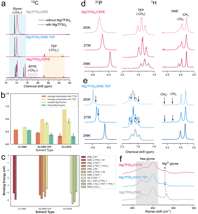
We carried out nuclear magnetic resonance (NMR) spectroscopy to understand the solvation structure of the electrolytes in these CEPE systems. Fig. 3(a) displays the 13C NMR spectra of various electrolytes at 298 K. In both Mg(TFSI)2/CEPE and Mg(TFSI)2/DME:TEP, the Mg2+–TEP interaction leads to high frequency shifts of the –CH2– groups in TEP by ∼3.7 and ∼3.4 ppm, respectively. This interaction is much stronger than that of Mg2+–DME in Mg(TFSI)2/DME, which only provokes a 0.5 ppm low frequency shift of the DME –CH2– group. This strong Mg2+–TEP interaction results in a large decrease of the full width at half maximum (FWHM) of DME (the –CH2– signal) by around 60% (Table S3, ESI†): a clear indication of a much lesser CIP fraction.28 This is in perfect accord with Raman analysis (Fig. S11, ESI†). A similar Mg2+–TEP interaction was observed in both Mg(TFSI)2/CEPE and Mg(TFSI)2/DME:TEP electrolytes (Fig. S12, ESI†), suggesting the consistent effect of reducing CIPs in all electrolytes with the presence of TEP.The reduction in CIP formation by TEP is further upheld by classical MD simulations (Fig. 3(b)). Mg2+ shows strong interaction with the oxygen of the P![[double bond, length as m-dash]](https://www.rsc.org/images/entities/char_e001.gif) O motif of TEP (Fig. S13, ESI†). The average Mg2+–TEP coordination increases from ∼0.8 in Mg(TFSI)2/DME:TEP to ∼1.1 in Mg(TFSI)2/CEPE. The fractions of isolated and paired Mg2+ ions – defined by solvation shells with zero and one TFSI− anion – were also calculated. The paired Mg2+ fractions from MD closely matches with the experimental CIP concentrations (Fig. S9, ESI†), which is especially impressive with a non-polarizable forcefield:41 the average paired Mg2+ fraction decreases from ∼0.45 in Mg(TFSI)2/DME (experimental CIP concentration: ∼40%) to ∼0.26 in Mg(TFSI)2/CEPE (experimental CIP concentration: ∼23%). Fig. S14 (ESI†) shows the increasing diversity of the solvation shell population distributions in Mg(TFSI)2/CEPE compared to that in Mg(TFSI)2/DME, which suggests that a higher electrolyte entropy enables complete salt [Mg(TFSI)2] dissociation and allows Mg2+ ions to form fully solvated clusters.42 Moreover, the average coordination between Mg2+ and TFSI− steadily falls with a concomitant rise in isolated Mg2+ and free TFSI− species (Fig. S15, ESI†). This is a consequence of the simultaneous competition between DME, TEP and G2 (in Mg(TFSI)2/CEPE) to displace the TFSI− anion from the Mg2+ solvation environment in the phosphate-added systems (Fig. S16, ESI†). The G2 molecules – with three polar O atoms – can maximally participate in tridentate coordination with Mg2+ ions, while DME is only capable of monodentate or bidentate coordination. Consequently, the average coordination between Mg and DME is significantly lower in the CEPE system (Fig. S16, ESI†). A sharp Mg–O radial distribution function (RDF) peak at ∼2.1 Å and the displaced position of the Mg–N RDF peak at ∼4 Å (Fig. S11, ESI†) confirms that the O from the sulfonyl group dominates the interaction between Mg2+ and TFSI− in the first solvation shell.43 The negligible coordination between Mg and BTFE (Fig. S17, ESI†) is consistent with previous studies.30,44 These results provide strong support to the experimental results and confirm the decrease of CIPs in both the Mg(TFSI)2/DME:TEP and Mg(TFSI)2/CEPE electrolytes.
O motif of TEP (Fig. S13, ESI†). The average Mg2+–TEP coordination increases from ∼0.8 in Mg(TFSI)2/DME:TEP to ∼1.1 in Mg(TFSI)2/CEPE. The fractions of isolated and paired Mg2+ ions – defined by solvation shells with zero and one TFSI− anion – were also calculated. The paired Mg2+ fractions from MD closely matches with the experimental CIP concentrations (Fig. S9, ESI†), which is especially impressive with a non-polarizable forcefield:41 the average paired Mg2+ fraction decreases from ∼0.45 in Mg(TFSI)2/DME (experimental CIP concentration: ∼40%) to ∼0.26 in Mg(TFSI)2/CEPE (experimental CIP concentration: ∼23%). Fig. S14 (ESI†) shows the increasing diversity of the solvation shell population distributions in Mg(TFSI)2/CEPE compared to that in Mg(TFSI)2/DME, which suggests that a higher electrolyte entropy enables complete salt [Mg(TFSI)2] dissociation and allows Mg2+ ions to form fully solvated clusters.42 Moreover, the average coordination between Mg2+ and TFSI− steadily falls with a concomitant rise in isolated Mg2+ and free TFSI− species (Fig. S15, ESI†). This is a consequence of the simultaneous competition between DME, TEP and G2 (in Mg(TFSI)2/CEPE) to displace the TFSI− anion from the Mg2+ solvation environment in the phosphate-added systems (Fig. S16, ESI†). The G2 molecules – with three polar O atoms – can maximally participate in tridentate coordination with Mg2+ ions, while DME is only capable of monodentate or bidentate coordination. Consequently, the average coordination between Mg and DME is significantly lower in the CEPE system (Fig. S16, ESI†). A sharp Mg–O radial distribution function (RDF) peak at ∼2.1 Å and the displaced position of the Mg–N RDF peak at ∼4 Å (Fig. S11, ESI†) confirms that the O from the sulfonyl group dominates the interaction between Mg2+ and TFSI− in the first solvation shell.43 The negligible coordination between Mg and BTFE (Fig. S17, ESI†) is consistent with previous studies.30,44 These results provide strong support to the experimental results and confirm the decrease of CIPs in both the Mg(TFSI)2/DME:TEP and Mg(TFSI)2/CEPE electrolytes.
DFT calculations were further performed to calculate the binding energies of the predominant clusters in these electrolytes (Fig. S14, ESI†). The results in Fig. 3(c) demonstrate that the clusters with CIPs in the solvation shells (hatched bars) consistently exhibit a greater binding energy than fully solvent-coordinated Mg2+, in turn suggesting a higher desolvation energy for the charge transfer process.45,46 The direct correlation between binding and desolvation energy is already established.47 The trends in Fig. 3(c) indicate that the large decrease in CIPs and increase in exclusively solvent-coordinated Mg2+ solvated clusters promote a facile desolvation process during charge transfer.48 The results also affirm that the observed fast kinetics of Mg plating/stripping in the CEPE system is induced by higher exchange current densities and surface energies which in turn promotes uniform Mg electrodeposition (see below).45
The bulk dynamics of ethers and TEP in these electrolytes were explored by conducting variable temperature NMR. In both 31P and 1H spectra of Mg(TFSI)2/CEPE, no new peaks were found at low temperature (Fig. 3(d)). In Mg(TFSI)2/DME:TEP, however, the single 31P resonance at 298 K was gradually split into two at below 273 K (Fig. 3(e)), along with the appearance of more –CH3 and –CH2– signals of TEP in 1H spectra at low temperature (Fig. S18, ESI†). This peak splitting suggests Mg2+ is undercoordinated with TEP (e.g. fewer Mg2+–TEP bonds in the presumably six-coordinated Mg2+ solvation sheath). In addition, the Mg2+–DME interaction in Mg(TFSI)2/DME:TEP shows similar undercoordination with two new higher-frequency peaks appearing in 1H spectra below 273 K. These were assigned to the –CH2– and –CH3 groups of DME by carrying out a Heteronuclear Single Quantum Coherence (HSQC) experiment (Fig. S19, ESI†). The new peaks can be ascribed to the slow exchange rate of DME molecules in different bound environments,30,49 leading to peak separation at low temperatures. The addition of G2 and BTFE in Mg(TFSI)2/CEPE effectively enhances the exchange rate, owing to the absence of such undercoordination behavior. This is because G2 is known to exchange much faster than DME while BTFE barely coordinates with Mg2+,30 in turn indicating decreased Mg2+–glyme interaction by co-ethers. This is verified by the blue shift and decreased intensity of coordinated glyme signals in the Raman spectra (Fig. 3(f)),12,34 As a consequence, a lower desolvation penalty can be expected in Mg(TFSI)2/CEPE, which explains the much enhanced kinetics of Mg plating/stripping relative to Mg(TFSI)2/DME:TEP (Fig. 1).
Tuning nanoscale and dendrite-free Mg plating/stripping morphology
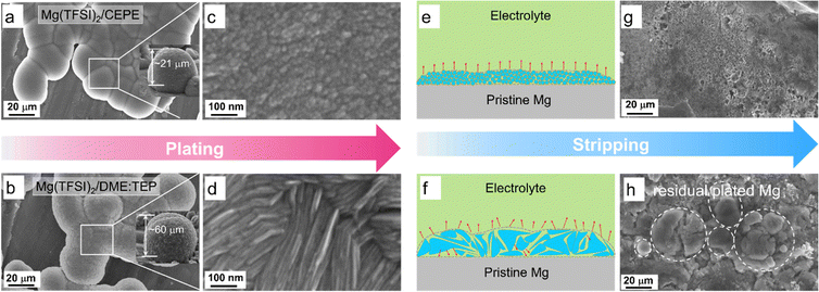
To delve more into the function of co-ethers in sustained long-term Mg plating/stripping, we used scanning electron microscopy (SEM) coupled with EDX to probe the Mg electrodes retrieved from Mg||Mg symmetric cells. In Mg(TFSI)2/CEPE, nanoscale Mg nuclei of around 10 nm were observed with much smoother surface morphology that merged into globules (Fig. 4(a), (c) and Fig. S20, ESI†). The X-ray diffraction (XRD) pattern of plated Mg confirms that these deposited globules are agglomerated fine particles (Fig. S21, ESI†). In Mg(TFSI)2/DME:TEP, however, Mg deposits as microscale flaky crystals with a dimension of ∼500 nm (Fig. 4(b) and (d)). Mg plated in Mg(TFSI)2/DME yielded a spherical morphology of core–shell multilayers (Fig. 2(e) and Fig. S22, ESI†). The nanoscale nucleation and growth in Mg(TFSI)2/CEPE leads to denser and thinner hemisphere deposition with a thickness of ∼20 μm, in contrast to ∼60 μm in Mg(TFSI)2/DME:TEP. The uniform deposition in CEPE can be attributed to the increase in isolated Mg2+ clusters with lower binding energies and weakened Mg2+–DME interactions (Fig. 3) that results in a faster desolvation process at the Mg/electrolyte interface. We thus expected a more homogeneous distribution of local interfacial currents during stripping (Fig. 4(e) and (f)), which was verified by the smoother and cleaner stripping morphologies in Mg(TFSI)2/CEPE (Fig. 4(g)). In Mg(TFSI)2/DME:TEP, by comparison, large quantities of cracked Mg globules were observed on the cycled electrode (Fig. 4(h)). We believe that voids can be formed between the flaky crystals due to a non-uniform distribution of stripping current (Fig. S23, ESI†), which leads to electrolyte penetration through the plated Mg globules and results in inactive Mg.50 With continuous plating/stripping, the accumulation of cracked globules leads to a mossy surface that can easily induce short circuits (Fig. S24, ESI†). Therefore, Mg||Mg symmetric cells show outstanding stability with Mg(TFSI)2/CEPE but quickly short with Mg(TFSI)2/DME:TEP. In Mg(TFSI)2/DME, the thick insulating passivation layer resulting from electrolyte decomposition significantly blocks the electron transfer pathway and thus Mg dissolution during the stripping process, preserving the original spherical morphology (Fig. S25, ESI†).Interfacial SEI chemistry on the plated Mg surface
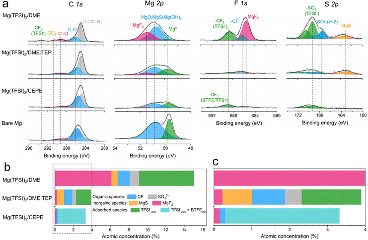
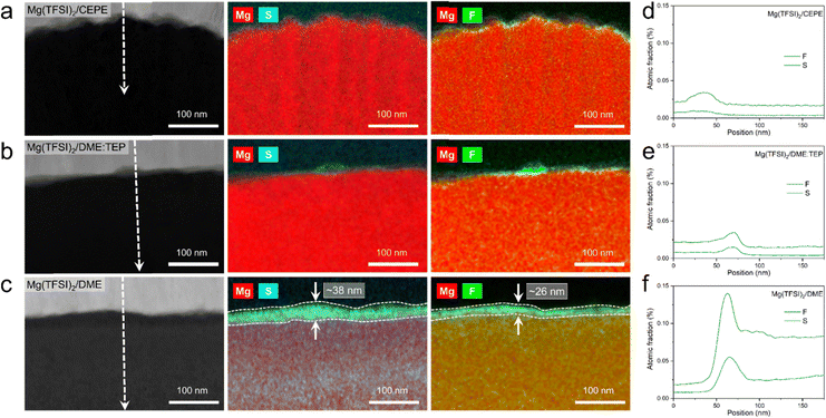
High-resolution X-ray photoelectron spectroscopy (XPS) was used to investigate SEI compositions on the plated Mg surface in different electrolytes. For Mg cycled in the baseline Mg(TFSI)2/DME (Fig. 5(a)), we observed abundant surface species including MgF2 (688.5 eV, F 1s), MgS (163.2 eV, S 2p), –CF (686.2 eV, F 1s) and −SOx (x < 2, 167.4 eV, S 2p). These likely result from the reduction of TFSI− anions. In addition, F-rich –CF3 (688.6 eV, F 1s) and –SO2 (169.2 eV, S 2p) signals imply copious adsorption of TFSI− anions on the Mg surface (Fig. 5(b)). These results correlate with the large fraction of CIPs in the electrolyte, which facilitates the adsorption and reduction of TFSI− on the Mg surface to form the passivation layer. Owing to the significantly decreased CIPs in Mg(TFSI)2/DME:TEP, intensities in the F 1s and S 2p region are greatly diminished on plating Mg, showing effective suppression of these anion-related species. In Mg(TFSI)2/CEPE, no evident of anion-derived species were observed. We attribute this to the G2-optimized solvation structure and the adsorption of BTFE on the Mg surface that further suppresses the decomposition of TFSI− (Fig. 5(c)). Indeed, the Mg(TFSI)2/CEPE without trace BTFE shows more electrolyte decomposition products (Fig. S26, ESI†), with significantly poorer kinetics of Mg plating/stripping (Fig. S27, ESI†). In addition, no phosphorus signals were found for electrodes retrieved from both Mg(TFSI)2/DME:TEP and Mg(TFSI)2/CEPE (Fig. S28, ESI†), suggesting TEP is not decomposed. This is in strong contrast to previous studies on the TMP additive that showed its extensive reduction to form a Mg3(PO4)2-rich interface,34,35 which implies additive consumption causes the continuous increase of voltage hysteresis during Mg plating/stripping. While it is surprising that the additional –CH2 group in TEP results in remarkably increased stability against electrochemical reduction, we speculate that this originates from a steric effect. This results in different Mg2+ solvation structures that presumably exist with higher stability.40 Identifying the exact origin of this difference is beyond the scope of this work and will be part of a future study.The structural characteristics and chemical mapping of these interfaces formed on Mg were further probed using cryogenic focused ion beam (Cryo-FIB) milling and transmission electron microscopy (TEM). Fig. 6(a) and (b) shows the high-angle annular dark-field (HAADF) images at the surface of Mg deposited in Mg(TFSI)2/CEPE and Mg(TFSI)2/DME:TEP, along with maps showing the Mg/S and Mg/F elemental distribution. Trace amounts of S and F can be observed on the Mg surface that originate from the formation of a very thin SEI. This is in good accord with the XPS results above. The thickness cannot be well defined due to the low quantity of S/F present that is comparable to the background noise. In contrast, in baseline Mg(TFSI)2/DME (Fig. 6(c)), a ∼30 nm thick S-rich and F-rich passivation layer is formed. In addition to the accumulation of S/F at the interface, significant amounts decorate the underlying Mg region. In both Mg(TFSI)2/DME:TEP and Mg(TFSI)2/CEPE, the S/F species were greatly diminished at both surface and Mg regions, as confirmed by EDX line scan analysis (Fig. 6(d)–(f) and Fig. S29, ESI†).
High-voltage stability in Mg-organic cathode full cells
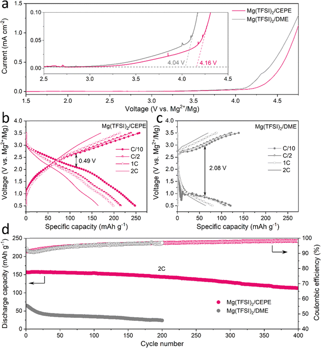
To assess the anodic stability of the CEPEs, linear scan voltammetry (LSV) was performed on three-electrode cell with commercial Al foil as a working/counter electrode and Mg as the reference electrode. A typical scan rate of 5 mV s−1 was used in the measurements.17 All electrolytes exhibit an oxidation stability of around 4 V on Al foil (Fig. 7(a) and Fig. S30, ESI†), consistent with previously reported Mg(TFSI)2/glyme electrolyte systems.25,33 The low anodic current between 3 V to 4 V (note y-scale in the inset) is attributed to the oxidation of trace impurities/moisture in the electrolyte, or minor Al corrosion in the presence of Mg(TFSI)2 as commonly reported.25 We chose polyaniline (PANI) as a readily available, high-voltage (∼2.3 V) organic cathode material to benchmark the oxidative stability of the Mg(TFSI)2/CEPE system. We demonstrate the cycling of a PANI||Mg cell up to a high cut-off voltage of 3.5 V (Fig. 7(b)), providing a specific discharge capacity of 250 mA h gPANI−1 at C/10 (1C = 250 mA gPANI−1) with an average discharge voltage of ∼2.05 V. The dominant TFSI− anion storage chemistry is confirmed by EDX analysis (Fig. S31, ESI†), in accord with previous studies.51 A very large specific capacity of PANI is obtained in part due to CEPE's good oxidative stability, whereas the use of chloride-based electrolytes in previous studies51 limits PANI's high-voltage application and hence gives rise to a low specific capacity of less than 150 mA h gPANI−1 in the range of 0.1–2.8 V. More importantly, PANI in Mg(TFSI)2/CEPE shows excellent rate capability, with a capacity of 239, 215, and 165 mA h gPANI−1 at C/2, 1C, and 2C, respectively. In the baseline Mg(TFSI)2/DME electrolyte, however, a high voltage polarization of around 2.08 V was observed for the PANI||Mg cell at C/10 (Fig. 7(c)), yielding a discharge capacity of only 120 mA h g−1. The long-term cycling stability of PANI||Mg cell was further investigated at a 2C rate (Fig. 7(d) and Fig. S32, S33, ESI†). In Mg(TFSI)2/CEPE, the cell retains a high discharge capacity of ∼ 113 mA h g−1 with 99% CE after 400 cycles, corresponding to a capacity retention of over 72%. In contrast, a low discharge capacity of only 65 mA h g−1 was obtained in Mg(TFSI)2/DME, which quickly drops to around 24 mA h g−1 after 200 cycles due to the poor kinetics of Mg plating/stripping. The desirable performance of PANI in CEPE under high voltage conditions confirms the high oxidative stability of CEPE and suggests a facile anion desolvation process due to suppressed CIP formation. This in turn results in facile desolvation of Mg2+ at the cathode side, as proven by using an n-type pyrene-4,5,9,10-tetraone (PTO) cathode that also shows good rate performance (Fig. S34, ESI†). However, the PTO||Mg cell shows limited cycling stability due to the relatively high solubility of Mg1PTO as reported,14 and was not pursued further in this study.Conclusions
A new class of co-ether phosphate electrolytes (CEPE) is developed for stable and high-voltage Mg batteries. This electrolyte system relies on two key components: ethyl phosphate to unlock the activity of Mg2+/Mg redox and co-ether solvents to improve the kinetics and stability of Mg plating/stripping. The complex interactions between cation, anion and solvents were revealed by advanced spectroscopies and MD simulations, providing new design principles for efficient Mg electrolytes. The use of a cost-effective and commercially available Mg salt – Mg(TFSI)2 – simplifies scalability. Importantly, it demonstrates the effectiveness of tuning the solvent to disrupt ion-pair formation, which would not be evident with a bulky-anion salt such as Mg(CB11H12)2. Dendrite-free Mg plating/stripping with Mg(TFSI)2 is thus achieved for over 7000 hours (∼10 months) at a practical areal capacity of 2 mA h cm−2. PANI||Mg batteries assembled with the optimized electrolyte provide a capacity of 240 mA h gPANI−1 at a C/2 rate, and perform over 400 cycles up to an operating voltage of 3.5 V at a 2C rate. These showcase the 4.15 V anodic stability of the MgTFSI2-CEPE system and suggest facile anion desolvation due to suppressed contact-ion pair formation. Furthermore, ready desolvation of the Mg2+ cation is demonstrated by good rate performance of a state-of-the-art n-type pyrene-4,5,9,10-tetraone (PTO) cathode. Our weakly ion pairing approach effected by solvent design opens up new frontiers for low-cost and high-voltage electrolyte development that could take advantage of facile desolvation processes at the interfaces, establishing a platform for new avenues of investigation for next generation energy storage in RMBs.Author contributions
C. L. and L. F. N. designed this study. C. L. prepared the electrolytes, carried out the characterization and all the electrochemical measurements. R. D. G. and K. A. P. performed molecular dynamics and DFT calculation. A. S. performed NMR measurements. C. L. and L. F. N. wrote the manuscript with contributions from the other authors.Conflicts of interest
The authors declare no competing interests.Acknowledgements
This work was financially supported by the Joint Centre for Energy Storage Research, an Energy Innovation Hub funded by the US. Department of Energy, Office of Science, Basic Energy Sciences. We would like to thank Dr P. Broderson (University of Toronto) for carrying out the XPS data collection, Dr Ryan Kingsbury, and Dr Jingyang Wang for guidance with the MD calculations, Evan Spotte-Smith for insights on the CIP decomposition and Alexander Epstein for helpful discussions regarding the DFT calculations. L.F.N also acknowledges NSERC for platform support through the Discovery Grant and Canada Research Chair programs.References
- R. Mohtadi, O. Tutusaus, T. S. Arthur, Z. Zhao-Karger and M. Fichtner, Joule, 2021, 5, 581–617 CrossRef CAS.
- Y. Tian, G. Zeng, A. Rutt, T. Shi, H. Kim, J. Wang, J. Koettgen, Y. Sun, B. Ouyang, T. Chen, Z. Lun, Z. Rong, K. Persson and G. Ceder, Chem. Rev., 2021, 121(3), 1623–1669 CrossRef CAS.
- M. Kar, O. Tutusaus, D. R. MacFarlane and R. Mohtadi, Energy Environ. Sci., 2019, 12, 566–571 RSC.
- Y. S. Meng, V. Srinivasan and K. Xu, Science, 2022, 378, 1065 CrossRef PubMed.
- H. Zhang, L. Qiao and M. Armand, Angew. Chem., Int. Ed., 2022, 61, e202214054 CrossRef CAS PubMed.
- P. Canepa, G. S. Gautam, D. C. Hannah, R. Malik, M. Liu, K. G. Gallaghe, K. A. Persson and G. Ceder, Chem. Rev., 2017, 117(5), 4287–4341 CrossRef CAS PubMed.
- R. Davidson, A. Verma, D. Santos, F. Hao, C. Fincher, S. Xiang, J. V. Buskirk, K. Xie, M. Pharr and P. P. Mukherje, ACS Energy Lett., 2019, 4(2), 375–376 CrossRef CAS.
- M. S. Ding, T. Diemant, R. J. Behm, S. Passerini and G. A. Giffin, J. Electrochem. Soc., 2018, 165, A1983 CrossRef CAS.
- Q. Pang, A. Shyamsunder, B. Narayanan, C. Y. Kwok, L. A. Curtiss and L. F. Nazar, Nat. Energy, 2018, 3, 783–791 CrossRef CAS.
- P. Canepa, S. Bo, G. S. Gautam, B. Key, W. D. Richards, T. Shi, Y. Tian, Y. Wang, J. Li and G. Ceder, Nat. Commun., 2017, 8, 1759 CrossRef.
- Y. Liang, H. Dong, D. Aurbach and Y. Yao, Nat. Energy, 2020, 5, 646–656 CrossRef CAS.
- Y. Sun, Y. Wang, L. Jiang, D. Dong, W. Wang, J. Fan and Y. Lu, Energy Environ. Sci., 2023, 16, 265–274 RSC.
- D. Aurbach, Z. Lu, A. Schechter, Y. Gofer, H. Gizbar, R. Turgeman, Y. Cohen, M. Moshkovich and E. Levi, Nature, 2000, 407, 724–727 CrossRef CAS.
- H. Dong, Y. Liang, O. Tutusaus, R. Mohtadi, Y. Zhang, F. Hao and Y. Yao, Joule, 2018, 3, 782–793 CrossRef.
- O. Tutusaus, R. Mohtadi, T. S. Arthur, F. Mizuno, E. G. Nelson and Y. V. Sevryugina, Angew. Chem., Int. Ed., 2015, 54, 7900–7904 CrossRef CAS.
- J. Luo, Y. Bi, L. Zhang, X. Zhang and T. L. Liu, Angew. Chem., Int. Ed., 2019, 58, 6967–6971 CrossRef CAS PubMed.
- J. T. Herb, C. A. Nist-Lund and C. B. Arnold, ACS Energy Lett., 2016, 1, 1227–1232 CrossRef CAS.
- Z. Zhao-Karger, M. E. G. Bardaji, O. Fuhr and M. Fichtner, J. Mater. Chem. A, 2017, 5, 10815–10820 RSC.
- T. Pavčnik, M. Lozinšek, K. Pirnat, A. Vizintin, T. Mandai, D. Aurbach, R. Dominko and J. Bitenc, ACS Appl. Mater. Interfaces, 2022, 14, 26766–26774 CrossRef.
- H. Dong, O. Tutusaus, Y. Liang, Y. Zhang, Z. Lebens-Higgins, W. Yang, R. Mohtadi and Y. Yao, Nat. Energy, 2020, 5, 1043–1050 CrossRef CAS.
- H. Nishida, T. Naoko, Y. Masaji, S. Takaaki and K. Hirsoshi, Bull. Chem. Soc. Jpn., 1984, 57, 2600–2604 CrossRef CAS.
- T. Mandai, ACS Appl. Mater. Interfaces, 2020, 12, 39135–39144 CrossRef CAS PubMed.
- W. Ren, D. Wu, Y. NuLi, D. Zhang, Y. Yang, Y. Wang, J. Yang and J. Wang, ACS Energy Lett., 2021, 6, 3212–3220 CrossRef CAS.
- K. Tang, A. Du, S. Dong, Z. Cui, X. Liu, C. Lu, J. Zhao, X. Zhou and G. Cui, Adv. Mater., 2020, 32, 1904987 CrossRef CAS.
- S. Ha, Y. Lee, S. W. Woo, B. Koo, J. Kim, J. Cho, K. T. Lee and N. Choi, ACS Appl. Mater. Interfaces, 2014, 6, 4063–4073 CrossRef CAS.
- M. Salama, I. Shterenberg, H. Gizbar, N. N. Eliaz, M. Kosa, K. Keinan-Adamsky, M. Afri, L. J. W. Shimon, H. E. Gottlieb, D. T. Major, Y. Gofer and D. Aurbach, J. Phys. Chem. C, 2016, 120, 19586–19594 CrossRef CAS.
- J. Eaves-Rathert, K. Moyer, M. Zohair and C. L. Pint, Joule, 2020, 4, 1324–1336 CrossRef CAS.
- N. N. Rajput, X. Qu, N. Sa, A. K. Burrell and K. A. Persson, J. Am. Chem. Soc., 2015, 137, 3411–3420 CrossRef CAS.
- A. Baskin and D. Prendergast, J. Phys. Chem. C, 2016, 120, 3583–3594 CrossRef CAS.
- N. T. Hahn, E. P. Kamphaus, Y. Chen, V. Murugesan, K. T. Mueller, L. Cheng and K. R. Zavadil, ACS Appl. Energy Mater., 2023, 6, 3264–3277 CrossRef CAS.
- Y. Yang, J. Wang, X. Du, H. Jiang, A. Du, X. Ge, N. Li, H. Wang, Y. Zhang, Z. Chen, J. Zhao and G. Cui, J. Am. Chem. Soc., 2023, 145, 12093–12104 CrossRef CAS PubMed.
- E. W. C. Spotte-Smith, S. M. Blau, D. Barter, N. J. Leon, N. T. Hahn, N. S. Redkar, K. R. Zavadil, C. Liao and K. A. Persson, J. Am. Chem. Soc., 2023, 145, 12181–12192 CrossRef CAS.
- S. Hou, X. Ji, K. Gaskell, P. Wang, L. Wang, J. Xu, R. Sun, O. Borodin and C. Wang, Science, 2021, 374, 172–178 CrossRef CAS.
- W. Zhao, Z. Pan, Y. Zhang, Y. Liu, H. Dou, Y. Shi, Z. Zuo, B. Zhang, J. Chen, X. Zhao and X. Yang, Angew. Chem., Int. Ed., 2022, 134, e202205187 CrossRef.
- S. Wang, K. Wang, Y. Zhang, Y. Jie, X. Li, Y. Pan, X. Gao, Q. Nian, R. Cao, Q. Li, S. Jiao and D. Xu, Angew. Chem., Int. Ed., 2023, e202304411 Search PubMed.
- B. D. Adams, J. Zheng, X. Ren, W. Xu and J.-G. Zhang, Adv. Energy Mater., 2018, 8, 1702097 CrossRef.
- S. Fan, S. Cora and N. Sa, ACS Appl. Mater. Interfaces, 2022, 14, 46635–46645 CrossRef CAS.
- Z. Lu, H. Yang, Q. Yang, P. He and H. Zhou, Angew. Chem., Int. Ed., 2022, 61, e202200410 CrossRef CAS PubMed.
- S. Son, T. Gao, S. P. Harvey, K. X. Steirer, A. Stokes, A. Norman, C. Wang, A. Cresce, K. Xu and C. Ban, Nat. Chem., 2018, 10, 532–539 CrossRef CAS PubMed.
- Y. Chen, Z. Yu, P. Rudnicki, H. Gong, Z. Huang, S. C. Kim, J. Lai, X. Kong, J. Qin, Y. Cui and Z. Bao, J. Am. Chem. Soc., 2021, 143, 18703–18713 CrossRef CAS PubMed.
- P. Kubisiak and A. Eilmes, J. Phys. Chem. C, 2018, 122, 12615–12622 CrossRef CAS.
- S. C. Kim, J. Wang, R. Xu, P. Zhang, Y. Chen, Z. Huang, Y. Yang, Z. Yu, S. T. Oyakhire, W. Zhang, L. C. Greenburg, M. S. Kim, D. T. Boyle, P. Sayavong, Y. Ye, J. Qin, Z. Bao and Y. Cui, Nat. Energy, 2023, 8, 814–826 CrossRef CAS.
- S. H. Lapidus, N. N. Rajput, X. Qu, K. W. Chapman, K. A. Persson and P. J. Chupas, Phys. Chem. Chem. Phys., 2014, 16, 21941–21945 RSC.
- W. W. A. van Ekeren, M. Albuquerque, G. Ek, R. Mogensen, W. R. Brant, L. T. Costa, D. Brandell and R. Younesi, J. Mater. Chem. A, 2023, 11, 4111–4125 RSC.
- D. T. Boyle, S. C. Kim, S. T. Oyakhire, R. A. Vilá, Z. Huang, P. Sayavong, J. Qin, Z. Bao and Y. Cui, J. Am. Chem. Soc., 2022, 144, 20717–20725 CrossRef CAS.
- Y. Wu, A. Wang, Q. Hu, H. Liang, H. Xu, L. Wang and X. He, ACS Cent. Sci., 2022, 8, 1290–1298 CrossRef CAS.
- J. Holoubek, H. Liu, Z. Wu, Y. Yin, X. Xing, G. Cai, S. Yu, H. Zhou, T. A. Pascal, Z. Chen and P. Liu, Nat. Energy, 2021, 6, 303–313 CrossRef CAS.
- B. Nan, L. Chen, N. D. Rodrigo, O. Borodin, N. Piao, J. Xia, T. Pollard, S. Hou, J. Zhang, X. Ji, J. Xu, X. Zhang, L. Ma, X. He, S. Liu, H. Wan, E. Hu, W. Zhang, K. Xu, X. Yang, B. Lucht and C. Wang, Angew. Chem., Int. Ed., 2022, 61, e202205967 CrossRef CAS PubMed.
- Y. Chen, R. Atwi, K. S. Han, J. Ryu, N. M. Washton, J. Z. Hu, N. N. Rajput, K. T. Mueller and V. Murugesan, J. Phys. Chem. B, 2021, 125, 12574–12583 CrossRef CAS.
- C. Fang, B. Lu, G. Pawar, M. Zhang, D. Cheng, S. Chen, M. Ceja, J. Doux, H. Musrock, M. Cai, B. Liaw and Y. S. Meng, Nat. Energy, 2021, 6, 987–994 CrossRef CAS.
- J. Tang and F. Xu, Mater. Lett., 2020, 320, 132365 CrossRef.
Footnote |
| † Electronic supplementary information (ESI) available. See DOI: https://doi.org/10.1039/d3ee02861e |
| This journal is © The Royal Society of Chemistry 2024 |

