 Open Access Article
Surface amorphization and functionalization of a NiFeOOH electrocatalyst for a robust seawater electrolyzer†
Hao
Wang
ac,
Nannan
Jiang
a,
Bing
Huang
a,
Qiangmin
Yu
*b and
Lunhui
Guan
 *a
*a
aState Key Laboratory of Structural Chemistry, Fujian Key Laboratory of Nanomaterials, and CAS Key Laboratory of Design and Assembly of Functional Nanostructures, Fujian Institute of Research on the Structure of Matter, Chinese Academy of Sciences, Fuzhou, Fujian 350002, China. E-mail: guanlh@fjirsm.ac.cn
bShenzhen Geim Graphene Center, Tsinghua-Berkeley Shenzhen Institute & Institute of Materials Research, Tsinghua Shenzhen International Graduate School, Tsinghua University, Shenzhen 518055, P. R. China. E-mail: yu.qiangmin@sz.tsinghua.edu.cn
cCollege of Chemistry, Fuzhou University, Fuzhou 350108, China
First published on 14th June 2024
Abstract
Hydrogen production of seawater electrolysis has attracted considerable interest due to the abundant seawater resources. However, the chloride ions (Cl−) in seawater not only corrode the electrodes but also cause side reactions, severely impacting the electrode efficiency and stability of the oxygen evolution reaction (OER) in seawater electrolysis. These challenges are the key factors limiting the development of seawater electrolysis technology. Here, we developed a surface-functionalized high-performance catalyst, which not only resists Cl− corrosion using surface-functionalized ions, but also improves the OER activity by surface amorphization. The designed catalyst (Ru0.1-NiFeOOH/PO43−) is composed of Ru0.1-NiFeOOH and surface phosphate. On the one hand, a small amount of Ru doping can increase the surface amorphization of NiFeOOH and thus improve the catalytic activity. On the other hand, the phosphates on Ru0.1-NiFeOOH are resistant to Cl− corrosion, which in turn improves the electrode stability. This catalyst demonstrates robust performance operation over 1000 h in alkaline seawater solutions at an industrial current density of 0.5 A cm−2. The anion exchange membrane seawater electrolyzer assembled with Ru0.1-NiFeOOH/PO43− only needs 1.6 V to achieve 0.5 A cm−2 when powered by sustainable solar energy. The electrolyzer efficiency is 75.1% at 0.5 A cm−2, which is superior to the 2030 technical target of 65% set by the U.S. DOE and most reported work. This work offers a new perspective for designing efficient and stable catalysts and is of great significance for advancing seawater electrolysis technology.
Broader contextHydrogen production by seawater electrolysis has gradually attracted considerable interest due to freshwater scarcity. However, the chloride ions (Cl−) in seawater seriously affect the selectivity of the anode catalyst for the oxygen evolution reaction (OER) and the electrode lifetime. Transition metal hydroxyl oxides (M–OOH) are regarded as the active phase of the OER, which suffers from the problems of difficult exposure of internal active sites and poor resistance to Cl− corrosion. Herein, we report the optimization of the active site structure through heteroatom doping to promote M–OOH surface amorphization coupled with surface functionalization to enhance the catalytic activity and Cl− corrosion resistance of the catalyst. Meanwhile, experimental characterization combined with theoretical calculations demonstrated the effectiveness of the above strategies. This work provides a good reference for the rational design of effective and stable catalysts for seawater electrolysis. |
Introduction
The overuse of fossil energy is causing an unprecedented energy and environmental crisis.1 In response to this crisis, the scientific research and industrial sectors are accelerating their search for sustainable, environmentally friendly, and low-carbon energy alternatives.2 Among many candidates, hydrogen (H2) energy, with pollution-free and high-efficiency properties, is the well-known ideal energy.3,4 H2 produced by water electrolysis using renewable energy is a promising technology, which is favorable to energy and environmental sustainability.5,6 In the backdrop of increasing global freshwater scarcity, the exploitation of seawater, which constitutes 96.5% of the water resources, emerges as a potential hydrogen-containing resource.7 Meanwhile, combining seawater electrolysis with solar energy is a more promising technology for green H2 production.8 However, the inorganic salt, especially chloride ions in seawater, will corrode the electrode substrate and active sites of the catalysts.9 Currently, seawater electrolysis is divided into desalination followed by electrolysis and direct electrolysis.10,11 Xie et al. used a waterproof breathable membrane to achieve the separation of water and ions, while it shows poor performance at high current densities due to the insufficient supply of water to the system.12 Direct seawater electrolysis will allow chloride ions (Cl−) to be adsorbed on the electrode surface, resulting in the electrode being corroded. In addition, the chlorine evolution reaction will be triggered under high applied potentials. Therefore, it is urgent to develop corrosion-resistance and high-performance catalysts to reduce the electrode degradation and improve the oxygen evolution reaction (OER) selectivity, while such catalysts have not yet been developed.13Recently, transition metal-based catalysts especially layered double hydroxides (LDHs), are increasingly valued for their low cost, high efficiency and environmental benefits.14–17 However, Cl− may promote the corrosion of metal ions on the surface of LDHs, leading to active site destruction. Yu et al. used CoCu LDH doped with heteroatoms (Ni, Fe) to split seawater. The heteroatom doped CoCu LDH shows a low overpotential of 315 mV at 100 mA cm−2, but the stability was limited to 50 h due to the Cl− corroding the electrodes.18 Consequently, the LDHs need to be modified to improve their corrosion-resistance. Shao et al. modified NiFe LDH with molybdate (MoO42−). The modified NiFe LDH showed excellent stability of 550 h but a large overpotential of 332 mV at 100 mA cm−2.19 These results show that the introduction of heteroatoms and anions can improve the activity and stability of the catalysts, respectively. Nevertheless, it is challenging to introduce high active sites in the electrode structure while guaranteeing its corrosion resistance of Cl−.
Here, we designed a Ru0.1-NiFeOOH/PO43− catalyst from the perspectives of surface amorphization and functionalization. Among them, Ru doping accelerated the amorphization process of the catalyst, thus enhancing the catalytic activity of the electrode. Meanwhile, the in situ generated PO43− exhibits electrostatic repulsion against Cl− in seawater, improving the corrosion-resistance ability of the electrode. The results demonstrate that this strategy enables Ru0.1-NiFeOOH/PO43− to exhibit a low overpotential of 255 mV under 10 mA cm−2 in seawater electrolyte. Moreover, the catalyst operates stably at 0.5 A cm−2 in seawater electrolytes over 1000 h. Notably, we assembled the Ru0.1-NiFeOOH/PO43− catalyst in an anion exchange membrane (AEM) electrolyzer and powered it by solar energy. This electrolyzer requires only 1.6 V to achieve 0.5 A cm−2. These results indicate that the strategy of surface amorphization paired with functionalization enables the catalyst to exhibit excellent catalytic activity and stability. This work not only addresses the technical challenges in seawater electrolysis, but also provides an economical and feasible solution for H2 production with rich seawater and renewable energy.
Results and discussion
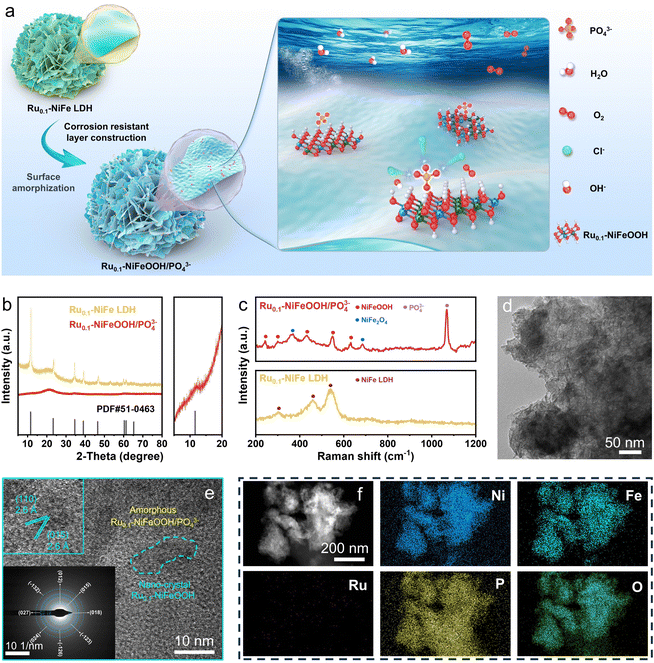
The Ru0.1-NiFeOOH/PO43− catalyst was synthesized by an electrochemical activation strategy, while the compositional information of the pre-catalyst Ru0.1-NiFeP is shown in Fig. S1–S4 (ESI†). As illustrated in Fig. 1a, in situ generated PO43− adsorbed on the surface of Ru0.1-NiFeOOH, which can electrostatically repel Cl− from seawater and avoid the active sites being corroded. Fig. 1b and Fig. S5 (ESI†) exhibit a phase transition from crystallization to amorphization between Ru0.1-NiFe LDH and Ru0.1-NiFeOOH/PO43−. Although the characteristic peak of NiFeOOH near 12° can still be observed, its crystallinity is quite low. Fig. S6 (ESI†) shows no peaks for Ni2P and FeP, which confirms the absence of residual NiFeP. These findings show that the electrochemical activation strategy significantly destroys the NiFeOOH lattice, resulting in a high degree amorphization of the catalyst surface. In the Raman spectrum (Fig. 1c), the Ru0.1-NiFeOOH/PO43− exhibits two characteristic peaks located at 248 and 306 cm−1, corresponding to the Ni–O/Fe–O vibration modes in the NiFeOOH. The characteristic peaks at 430, 554, and 625 cm−1 are attributed to lattice vibrations of the NiFeOOH. Additionally, the characteristic peak at 1068 cm−1 corresponds to the PO43−.20 The literature indicates that the characteristic peaks at 365 and 699 cm−1 can be attributed to the NiFe2O4 spinel structure, which involves the evolution cycle of Ni2+/3+ and Fe2+/3+ active sites.21 These results reveal that the PO43− functionalized Ru0.1-NiFeOOH electrode was prepared well. The transmission electron microscopy (TEM) image (Fig. 1d) shows that an amorphous layer formed on Ru0.1-NiFeOOH/PO43−, further confirming its larger specific surface area compared to pre-activation. In contrast to the high crystallinity of Ru0.1-NiFe LDH (Fig. S7, ESI†), the high-resolution transmission electron microscopy (HR-TEM) image (Fig. 1e) shows the amorphization of Ru0.1-NiFeOOH/PO43−, with a few remaining NiFeOOH nanocrystals. The illustration in Fig. 1e shows the SAED pattern of Ru0.1-NiFeOOH/PO43−, displaying no diffraction spots. This indicates the absence of Ru metal particles or nanoclusters and suggests that Ru is incorporated as a dopant in the NiFeOOH structure. Energy dispersive spectroscopy (EDS) analysis indicates that Ni, Fe and Ru elements are homogeneously distributed over Ru0.1-NiFeOOH/PO43− (Fig. 1f and Table S1, ESI†).X-ray photoelectron spectroscopy (XPS) survey results indicate that the Ru0.1-NiFeOOH/PO43− contains Ni, Fe, P and O, as well as trace Ru elements (Fig. S8, ESI†). High resolution XPS spectra of Ni 2p and Fe 2p (Fig. 2a and b) indicate that the characteristic peaks of Ni–P and Fe–P disappeared, and the peak of phosphates was observed after electrochemical activation (Fig. 2c and Fig. S9, ESI†).22 This result indicates that the Ru0.1-NiFeOOH catalyst is functionalized by the phosphates. For Ru0.1-NiFeP, the peak at 129.5 eV is attributed to P–Ni/Fe, while the peak at 133.6 eV is attributed to the oxidized phosphate species.23 In Fig. 2d, a shift of the Ru 3d5/2 peak from 361.3 eV to 362.2 eV is observed, demonstrating the generation of high-valence Ru. This leads to a decrease of Ru–O bond length, which promotes lattice distortion and accelerates the amorphization of the NiFeOOH surface.24 Meanwhile, the content of oxygen vacancies on the Ru0.1-NiFeOOH/PO43− surface was significantly increased (Fig. S10, ESI†), which is a major factor leading to the amorphous structure on the Ru0.1-NiFeOOH/PO43− surface.25 The presence of oxygen vacancies reduces the charge transfer resistance and enhances the charge transfer capability of the catalyst.26 All of the results demonstrate the synthesis of surface amorphization and phosphate functionalization of the Ru0.1-NiFeOOH/PO43− electrocatalyst.
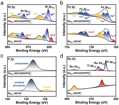 | ||
| Fig. 2 XPS spectra of (a) Ni 2p, (b) Fe 2p, (c) P 2p and (d) Ru 3d of Ru0.1-NiFeOOH/PO43− and Ru0.1-NiFeP. | ||
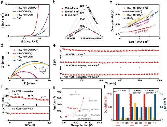
The OER performance of the optimized Ru content in Ru0.1-NiFeOOH/PO43− (normalized by the catalyst surface area) was first evaluated in a three-electrode cell system (Fig. S11, ESI†). Fig. 3a shows the linear sweep voltammetry (LSV) curves of Ru0.1-NiFeOOH/PO43−, NiFeOOH/PO43−, Ru0.1-NiFeOOH, and commercial RuO2 in 1 M KOH + seawater electrolyte. The results show that Ru0.1-NiFeOOH/PO43− requires only a low overpotential of 255 mV to achieve 10 mA cm−2, which is lower than that of NiFeOOH/PO43− (315 mV), Ru0.1-NiFeOOH (339 mV), and commercial RuO2 (343 mV). Fig. S12 (ESI†) shows that Ru doping shifts the oxidation–reduction peaks of Ru0.1-NiFeOOH/PO43− negatively and enlarges the peak area, indicating enhanced reaction kinetics and more active sites. Meanwhile, the LSV curves normalized by the electrochemical surface area (Fig. S13, ESI†) show that Ru0.1-NiFeOOH/PO43− has better intrinsic catalytic activity than the other three samples. Fig. 3b shows the catalytic performance of Ru0.1-NiFeOOH/PO43− in different electrolytes (1 M KOH, 1 M KOH + 0.5 M NaCl, and 1 M KOH + seawater) (Table S2, ESI†). The results indicate that Ru0.1-NiFeOOH/PO43− exhibits similar performance in both 1 M KOH and 1 M KOH + 0.5 M NaCl, and this suggests that the PO43− is effective in repelling Cl−. Furthermore, the faradaic efficiency of oxygen production for Ru0.1-NiFeOOH/PO43− is close to 100% in 1 M KOH + seawater electrolyte (Fig. S14, ESI†), implying that the electrical energy applied is predominantly dedicated to facilitating the OER. The Tafel slope of Ru0.1-NiFeOOH/PO43− is 47.5 mV dec−1 (Fig. 3c), which is lower than that of NiFeOOH/PO43− (77.9 mV dec−1), Ru0.1-NiFeOOH (105.4 mV dec−1), and RuO2 (111.9 mV dec−1), indicating the fast OER kinetics of the Ru0.1-NiFeOOH/PO43− catalyst. Additionally, electrochemical impedance spectroscopy (EIS) shows that Ru0.1-NiFeOOH/PO43− exhibits the smallest charge transfer resistance during the OER process (Fig. 3d, inset shows the equivalent circuit diagram and fitted data in Table S3, ESI†), proving its higher conductivity and faster charge transfer rate than contrasting samples.
Fig. 3e exhibits the superior stability of Ru0.1-NiFeOOH/PO43− in three different electrolytes, particularly under the harsh condition of 6 M KOH + seawater. In contrast, the Ru0.1-NiFeOOH electrode was broken and deactivated within no more than 2 h in the 6 M KOH + seawater electrolyte at 0.5 A cm−2 (Fig. S15, ESI†). Fig. 3f and Fig. S16 (ESI†) demonstrate that the Ru0.1-NiFeOOH/PO43− exhibits superior stability compared to Ru0.1-NiFeOOH at different operating temperatures and in a high chloride concentration electrolyte at 0.5 A cm−2. We have also investigated the Cl− oxidation of Ru0.1-NiFeOOH and Ru0.1-NiFeOOH/PO43− by the iodide titration method. Compared to the electrolyte of Ru0.1-NiFeOOH, which turned yellow after the stability test, the test electrolyte of Ru0.1-NiFeOOH/PO43− remained colorless, demonstrating that no oxidative chloride was generated during the stability test (Fig. S17 and S18, ESI†).27 These results reveal the effectiveness of the surface functionalization strategy of PO43− groups on the catalyst surface. Compared to most of the literature (Fig. 3g, h and Table S4, ESI†), the Ru0.1-NiFeOOH/PO43− has advantages in terms of overpotential, current density, and stability test time,18,27–31 which indicates the significant potential of Ru0.1-NiFeOOH/PO43− for industrial applications.
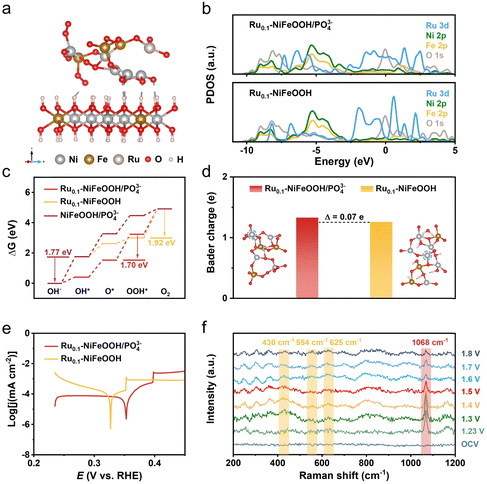
Density functional theory (DFT) calculations were conducted to obtain the free energy according to the typical adsorbate evolution mechanism proposed by Nørskov et al. (eqn (S1)–(S4) in the ESI†). As shown in Fig. 4a and Fig. S19 (ESI†), the Ru0.1-NiFeOOH/PO43− model was based on the hypothesis that an amorphous layer forms on the surface of Ru0.1-NiFeOOH after electrochemical activation, where the Ru0.1-NiFeOOH model was built on NiFeOOH, with Ru randomly substituting Ni and Fe atoms. The model of NiFeOOH/PO43− features PO43− adsorbed on the surface of the NiFeOOH (Fig. S20, ESI†). Density of states (DOS) plots (Fig. 4b) show that influenced by the hybridization effect, the formation of the amorphous layer on surface Ru0.1-NiFeOOH/PO43− leads to the PDOS transformation of the Ru 3d orbital from discrete peaks to continuous bands. This could potentially provide more adsorption sites and dissociation pathways, facilitating the adsorption and dissociation of intermediates. Consequently, it could enhance the reaction rate. According to the Sabatier principle, an ideal catalyst should exhibit moderate adsorption strength for intermediates. As depicted in Fig. 4c and Fig. S21 (ESI†), in the four-step proton-electron paired oxygen evolution reaction, the ideal barrier is 1.23 V. The amorphous Ru0.1-NiFeOOH/PO43− exhibits a lower Gibbs free energy compared to the Ru0.1-NiFeOOH and NiFeOOH/PO43−. Compared to the fourth rate-determining step (OOH* → O2) of Ru0.1-NiFeOOH, the amorphous Ru0.1-NiFeOOH/PO43− shifted the rate-determining step to the third step (O* → OOH*), accompanied by a significant barrier reduction (from 1.92 eV to 1.70 eV). Additionally, compared to NiFeOOH/PO43−, the rate-determining step for the Ru0.1-NiFeOOH/PO43− catalyst changes from OH− → OH* to O* → OOH*. This change may be due to the doping of Ru atoms, further resulting in lattice distortion. The distortion of the catalyst can alter the surface structure and provide more favorable adsorption sites for the reactants. This shift facilitated the effective progression of the OER. As shown in Fig. 4d, the amorphous Ru0.1-NiFeOOH/PO43− has more unsaturated or dangling bonds than Ru0.1-NiFeOOH, leading to an increase in surface charges. This modification in surface characteristics intensifies the electrostatic interactions between the catalyst's surface and various reaction intermediates such as OH−, O*, and OOH*.32Fig. 4e shows that the Ru0.1-NiFeOOH/PO43− exhibits a more positive corrosion potential than that of the Ru0.1-NiFeOOH. These findings indicate that the adsorption of PO43− on the Ru0.1-NiFeOOH surface can effectively repel Cl− from seawater, thereby enhancing the catalyst stability.
In situ Raman spectra are shown in Fig. 4f, no distinct characteristic peaks were detected at open-circuit voltage due to strong scattering from the electrolyte and weak signals from the sample itself. After applying 1.23 V for 25 minutes, a new peak emerged at 1068 cm−1, indicating the oxidation of P to PO43− in the Ru0.1-NiFeOOH/PO43− sample.33,34 Concurrently, a weaker peak at ∼248 cm−1 corresponding to the Ni–O/Fe–O vibration mode in the NiFeOOH appeared, suggesting that the oxidation of P atoms caused some PO43− to dissolve in the electrolyte, creating a favorable environment for the bonding of Ni and Fe sites with OH−.35,36 As the voltage increased further (from 1.30 to 1.80 V vs. RHE), more emerging characteristic peaks located at 306, 365, 430, 554, 625, 699, 800, and 988 cm−1 were detected in the Raman spectra. The peaks at 430, 554, and 625 cm−1 correspond to lattice vibrations of NiFeOOH,37,38 and the peaks at 306 and 699 cm−1 correspond to various Ni–O/Fe–O bond vibrations of Ni(Fe)(OH)2.39,40 Meanwhile, the intensity of the peak at 1068 cm−1 continuously decreased with rising voltage, indicating the gradual dissolution of PO43− into the electrolyte, further suggesting the transformation of PO43− sites into hydroxide/hydroxide oxide structures occupied by OH− or OOH−.20 The literature indicates that vibrational signals at 365 and 699 cm−1 can be attributed to the NiFe2O4 spinel structure, present in the evolution cycle of Ni2+/3+ and Fe2+/3+ active sites.21 Additionally, the characteristic peaks at 800 and 990 cm−1, similar to many in situ spectra reported in the literature,41,42 are attributed to the fluorescence background of the alkaline solution and the P–O bond stretching vibrations of dissolved phosphate.43,44 Compared to NiFeOOH/PO43− (Fig. S22, ESI†), the Ru0.1-NiFeOOH/PO43− catalyst exhibits a lower onset potential and a larger peak area for the NiFeOOH phase. This may be attributed to the Ru doping, which could induce lattice distortion and promote the structural evolution towards NiFeOOH, thereby accelerating the OER process. In summary, the in situ Raman spectra confirm the evolution of Ru0.1-NiFeOOH/PO43− into corresponding hydroxide and hydroxide oxide active species during the OER process.
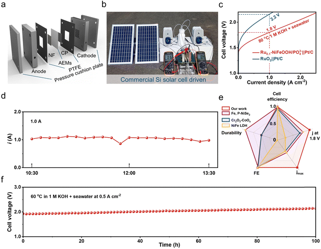
To evaluate the practical use of the Ru0.1-NiFeOOH/PO43− catalyst, we assembled it in an AEM electrolyzer and powered the electrolyzer by solar energy. The results show that the electrolyzer required only 1.6 V to achieve 0.5 A cm−2 in 6 M KOH + seawater electrolyte (Fig. 5a and b), demonstrating the best performance among most of the literature (Table S5 and Fig. S23, ESI†). The electrolyzer only needs 1.8 V to achieve 1.0 A cm−2, superior to that of the commercial RuO2-based AEM electrolyzer (2.2 V). During the stability test of the Ru0.1-NiFeOOH/PO43− catalyst assembled electrolyzer (Fig. 5c), the working current is maintained at 1.0 A using a regulator, and the electrolyzer could operate stably at 1.0 A for a long time (Fig. 5d). Compared with the reported literature (Fig. 5e, f and Table S6, ESI†),15,45,46 The Ru0.1-NiFeOOH/PO43− exhibits the advantages of low-applied voltage and superior stability at high current density, despite a certain increase in potential due to temperature loss. These results show the promise of Ru0.1-NiFeOOH/PO43− as an efficient and stable catalyst for industrial seawater electrolysis.
Conclusion
We have developed a dual-optimized function Ru0.1-NiFeOOH/PO43− catalyst for robust seawater electrolysis. First, we employed a trace Ru doping strategy to accelerate the amorphization of the NiFeOOH surface, potentially enhancing the active site availability and thereby improving the catalytic performance of Ru0.1-NiFeOOH/PO43−. Second, we introduced PO43− to resist Cl− corrosion on the Ru0.1-NiFeOOH surface, acting as an anion protective layer and achieving long-lasting seawater oxidation at high current density. Notably, the Ru0.1-NiFeOOH/PO43− electrode remains stable up to 1000 h at 1.0, 0.5, and 0.5 A cm−2 in 1 M KOH, 1 M KOH + seawater, and 6 M KOH + seawater electrolytes, respectively. We assembled the Ru0.1-NiFeOOH/PO43− in an AEM electrolyzer, which requires only 1.8 V to achieve 1.0 A cm−2 under industrial conditions. When the AEM electrolyzer is powered by solar energy, this system only needs 1.6 V to achieve 0.5 A cm−2, promising for the production of green H2 from renewable energy. Taken together, we believe that the surface synthetic strategy developed in this work will have a significant impact on seawater electrolysis technology and make a substantial contribution to global H2 energy development and sustainable energy utilization.Author contributions
H. W.: data curation, formal analysis, investigation, methodology, visualization, writing – original draft; N. N. J. and B. H.: writing – review & editing, methodology; Q. M. Y. and L. H. G.: resources, supervision, writing – review & editing. All authors read and commented on the manuscript.Data availability
The data that support the findings of this study are available from the corresponding author, upon reasonable request.Conflicts of interest
There are no conflicts to declare.Acknowledgements
We acknowledge financial support from the National Natural Science Foundation of China (no. 22171266 and 52303375) and the Shenzhen Basic Research Project (no. WDZC20220812141108001).References
- D. Shindell and C. J. Smith, Nature, 2019, 573, 408 CrossRef CAS PubMed.
- Y. J. Wang, R. Wang, K. Tanaka, P. Ciais, J. Penuelas, Y. Balkanski, J. Sardans, D. Hauglustaine, W. Liu, X. Xing, J. Li, S. Xu, Y. Xiong, R. Yang, J. Cao, J. Chen, L. Wang, X. Tang and R. Zhang, Nature, 2023, 619, 761 CrossRef CAS PubMed.
- J. A. Turner, Science, 2004, 305, 972 CrossRef CAS PubMed.
- S. van Renssen, Nat. Clim. Change, 2020, 10, 799 CrossRef.
- A. J. Shih, M. C. O. Monteiro, F. Dattila, D. Pavesi, M. Philips, A. H. M. da Silva, R. E. Vos, K. Ojha, S. Park, O. van der Heijden, G. Marcandalli, A. Goyal, M. Villalba, X. Chen, G. T. K. K. Gunasooriya, I. McCrum, R. Mom, N. López and M. T. M. Koper, Nat. Rev. Methods Primers, 2022, 2, 84 CrossRef CAS.
- H. Liu, X. Kang, T. Zhao, Z. Zhang, S. Ge, S. Hu, Y. Luo, F. Yang, S. H. Li, C. Sun, Q. Yu, H. M. Cheng and B. Liu, Sci. China Mater., 2022, 65, 3243 CrossRef CAS.
- M. A. Khan, T. Al-Attas, S. Roy, M. M. Rahman, N. Ghaffour, V. Thangadurai, S. Larter, J. Hu, P. M. Ajayan and M. G. Kibria, Energy Environ. Sci., 2021, 14, 4831 RSC.
- Y. Kuang, M. J. Kenney, Y. Meng, W.-H. Hung, Y. Liu, J. E. Huang, R. Prasanna, P. Li, Y. Li, L. Wang, M.-C. Lin, M. D. McGehee, X. Sun and H. Dai, Proc. Natl. Acad. Sci. U. S. A., 2019, 116, 6624 CrossRef CAS.
- M. Al-Abri, B. Al-Ghafri, T. Bora, S. Dobretsov, J. Dutta, S. Castelletto, L. Rosa and A. Boretti, npj Clean Water, 2019, 2, 2 CrossRef CAS.
- S. Ge, R. Xie, B. Huang, Z. Zhang, H. Liu, X. Kang, S. Hu, S. Li, Y. Luo, Q. Yu, J. Wang, G. Chai, L. Guan, H. M. Cheng and B. Liu, Energy Environ. Sci., 2023, 16, 3734 RSC.
- S. Hu, S. Ge, H. Liu, X. Kang, Q. Yu and B. Liu, Adv. Funct. Mater., 2022, 32, 2201726 CrossRef CAS.
- H. Xie, Z. Zhao, T. Liu, Y. Wu, C. Lan, W. Jiang, L. Zhu, Y. Wang, D. Yang and Z. Shao, Nature, 2022, 612, 673 CrossRef CAS PubMed.
- X. Kang, F. Yang, Z. Zhang, H. Liu, S. Ge, S. Hu, S. Li, Y. Luo, Q. Yu, Z. Liu, Q. Wang, W. Ren, C. Sun, H.-M. Cheng and B. Liu, Nat. Commun., 2023, 14, 3607 CrossRef CAS PubMed.
- H. Liu, W. Shen, H. Jin, J. Xu, P. Xi, J. Dong, Y. Zheng and S. Z. Qiao, Angew. Chem., Int. Ed., 2023, 62, e202311674 CrossRef CAS PubMed.
- S. Dresp, T. Ngo Thanh, M. Klingenhof, S. Brückner, P. Hauke and P. Strasser, Energy Environ. Sci., 2020, 13, 1725 RSC.
- L. Tan, J. Yu, C. Wang, H. Wang, X. Liu, H. Gao, L. Xin, D. Liu, W. Hou and T. Zhan, Adv. Funct. Mater., 2022, 32, 2200951 CrossRef CAS.
- Y. Yang, W. H. Lie, R. R. Unocic, J. A. Yuwono, M. Klingenhof, T. Merzdorf, P. W. Buchheister, M. Kroschel, A. Walker, L. C. Gallington, L. Thomsen, P. V. Kumar, P. Strasser, J. A. Scott and N. M. Bedford, Adv. Mater., 2023, 35, 2305573 CrossRef CAS PubMed.
- L. Yu, J. Y. Xiao, C. Q. Huang, J. Q. Zhou, M. Qiu, Y. Yu, Z. F. Ren, C. W. Chu and J. C. Yu, Proc. Natl. Acad. Sci. U. S. A., 2022, 119, e2202382119 CrossRef CAS PubMed.
- L. Shao, X. Han, L. Shi, T. Wang, Y. Zhang, Z. Jiang, Z. Yin, X. Zheng, J. Li, X. Han and Y. Deng, Adv. Energy Mater., 2023, 14, 2303261 CrossRef.
- P. Yan, Q. Liu, H. Zhang, L. Qiu, H. B. Wu and X.-Y. Yu, J. Mater. Chem. A, 2021, 9, 15586 RSC.
- Y. Li, Y. Wu, H. Hao, M. Yuan, Z. Lv, L. Xu and B. Wei, Appl. Catal., B, 2022, 305, 121033 CrossRef CAS.
- F. Hu, S. L. Zhu, S. M. Chen, Y. Li, L. Ma, T. P. Wu, Y. Zhang, C. M. Wang, C. C. Liu, X. J. Yang, L. Song, X. W. Yang and Y. J. Xiong, Adv. Mater., 2017, 29, 1606570 CrossRef PubMed.
- A. P. Grosvenor, S. D. Wik, R. G. Cavell and A. Mar, Inorg. Chem., 2005, 44, 8988 CrossRef CAS PubMed.
- Z. Y. He, J. Zhang, Z. H. Gong, H. Lei, D. Zhou, N. Zhang, W. J. Mai, S. J. Zhao and Y. Chen, Nat. Commun., 2022, 13, 2191 CrossRef CAS PubMed.
- J. S. Qu, W. Liu, R. Z. Liu, J. D. He, D. D. Liu, Z. C. Feng, Z. D. Feng, R. G. Li and C. Li, Chem Catal., 2023, 3, 100759 CrossRef CAS.
- H. Y. Zhang, L. L. Wu, R. H. Feng, S. H. Wang, C.-S. Hsu, Y. M. Ni, A. Ahmad, C. R. Zhang, H. F. Wu, H.-M. Chen, W. Zhang, Y. Li, P. Liu and F. Song, ACS Catal., 2023, 13, 6000–6012 CrossRef CAS.
- H. You, D. Wu, D. Si, M. Cao, F. Sun, H. Zhang, H. Wang, T. F. Liu and R. Cao, J. Am. Chem. Soc., 2022, 144, 9254 CrossRef CAS PubMed.
- L. Wu, F. Zhang, S. Song, M. Ning, Q. Zhu, J. Zhou, G. Gao, Z. Chen, Q. Zhou, X. Xing, T. Tong, Y. Yao, J. Bao, L. Yu, S. Chen and Z. Ren, Adv. Mater., 2022, 34, 2201774 CrossRef CAS PubMed.
- L. Yu, L. Wu, B. McElhenny, S. Song, D. Luo, F. Zhang, Y. Yu, S. Chen and Z. Ren, Energy Environ. Sci., 2020, 13, 3439 RSC.
- L. Wu, L. Yu, Q. Zhu, B. McElhenny, F. Zhang, C. Wu, X. Xing, J. Bao, S. Chen and Z. Ren, Nano Energy, 2021, 83, 105838 CrossRef CAS.
- X. Wang, X. Liu, S. Wu, K. Liu, X. Meng, B. Li, J. Lai, L. Wang and S. Feng, Nano Energy, 2023, 109, 108292 CrossRef CAS.
- S. Li, R. Ma, J. Hu, Z. Li, L. Liu, X. Wang, Y. Lu, G. E. Sterbinsky, S. Liu, L. Zheng, J. Liu, D. Liu and J. Wang, Nat. Commun., 2022, 13, 2916 CrossRef CAS PubMed.
- X. Chen, K. Xu, J. Li, X. Wang, T. Zhao, F. Liu, M. Yu and F. Cheng, Chin. Chem. Lett., 2023, 34, 108713 CrossRef CAS.
- X. Liu, J. Huang, T. Li, W. Chen, G. Chen, L. Han and K. Ostrikov, J. Mater. Chem. A, 2022, 10, 13448 RSC.
- L. Wei, M. Du, R. Zhao, F. Lv, L. Li, L. Zhang, D. Zhou and J. Su, J. Mater. Chem. A, 2022, 10, 23790 RSC.
- P. Zhou, S. Chen, H. Bai, C. Liu, J. Feng, D. Liu, L. Qiao, S. Wang and H. Pan, J. Colloid Interface Sci., 2023, 647, 65 CrossRef CAS PubMed.
- Q. Li, Q. Chen, S. Lei, M. Zhai, G. Lv, M. Cheng, L. Xu, H. Xu, Y. Deng and J. Bao, J. Colloid Interface Sci., 2023, 631, 56 CrossRef CAS.
- Y. Wu, Z. Xie, Y. Li, Z. Lv, L. Xu and B. Wei, Int. J. Hydrogen Energy, 2021, 46, 25070 CrossRef CAS.
- J. Xu, B.-X. Wang, D. Lyu, T. Wang and Z. Wang, Int. J. Hydrogen Energy, 2023, 48, 10724 CrossRef CAS.
- F. Tang, T. Liu, W. Jiang and L. Gan, J. Electroanal. Chem., 2020, 871, 114282 CrossRef CAS.
- O. Diaz-Morales, D. Ferrus-Suspedra and M. T. M. Koper, Chem. Sci., 2016, 7, 2639 RSC.
- Z. Qiu, Y. Ma and T. Edvinsson, Nano Energy, 2019, 66, 104118 CrossRef CAS.
- R. I. Bickley, H. G. M. Edwards, R. E. Gustarb and J. K. F. Tait, Mol. Struct., 1992, 273, 61 CrossRef CAS.
- C. A. Melendres, N. Camillone III and T. Tipton, Electrochim. Acta, 1989, 34, 281 CrossRef CAS.
- J.-F. Chang, G.-Z. Wang, Z.-Z. Yang, B.-Y. Li, Q. Wang, R. Kuliiev, N. Orlovskaya, M. Gu, Y.-G. Du, G.-F. Wang and Y. Yang, Adv. Mater., 2021, 33, 2101425 CrossRef CAS PubMed.
- J. Guo, Y. Zheng, Z. Hu, C. Zheng, J. Mao, K. Du, M. Jaroniec, S.-Z. Qiao and T. Ling, Nat. Energy, 2023, 8, 264 CAS.
Footnote |
| † Electronic supplementary information (ESI) available. See DOI: https://doi.org/10.1039/d4ey00106k |
| This journal is © The Royal Society of Chemistry 2024 |

