 Open Access Article
Creative Commons Attribution 3.0 Unported Licence
Climate change performance of hydrogen production based on life cycle assessment†
Gulam Husain
Patel
 *,
Jouni
Havukainen
,
Mika
Horttanainen
,
Risto
Soukka
and
Mari
Tuomaala
Department of Sustainability Science, LUT University, FI-53851, Lappeenranta, Finland. E-mail: Husain.Patel@lut.fi
First published on 2nd January 2024
Abstract
Hydrogen has the potential to revolutionize how we power our lives, from transportation to energy production. This study aims to compare the climate change impacts and the main factors affecting them for different categories of hydrogen production, including grey hydrogen (SMR), blue hydrogen (SMR-CCS), turquoise hydrogen (TDM), and green hydrogen (PEM electrolysis). Grey hydrogen, blue hydrogen, and turquoise hydrogen, which are derived from fossil sources, are produced using natural gas and green hydrogen is produced from water and renewable electricity sources. When considering natural gas as a feedstock, it is sourced from the pipeline route connected to Russia and through the liquefied natural gas (LNG) route from the USA. The life cycle assessment (LCA) result showed that grey hydrogen had the highest emissions, with the LNG route showing higher emissions, 13.9 kg CO2 eq. per kg H2, compared to the pipeline route, 12.3 kg CO2 eq. per kg H2. Blue hydrogen had lower emissions due to the implementation of carbon capture technology (7.6 kg CO2 eq. per kg H2 for the pipeline route and 9.3 kg CO2 eq. per kg H2 for the LNG route), while turquoise hydrogen had the lowest emissions (6.1 kg CO2 eq. per kg H2 for the pipeline route and 8.3 kg CO2 eq. per kg H2 for the LNG route). The climate change impact showed a 12–25% increase for GWP20 compared to GWP100 for grey, blue, and turquoise hydrogen. The production of green hydrogen using wind energy resulted in the lowest emissions (0.6 kg CO2 eq. per kg H2), while solar energy resulted in higher emissions (2.5 kg CO2 eq. per kg H2). This article emphasizes the need to consider upstream emissions associated with natural gas and LNG extraction, compression, liquefaction, transmission, and regasification in assessing the sustainability of blue and turquoise hydrogen compared to green hydrogen.
1. Introduction
The use of hydrogen as a clean energy transition fuel is receiving increasing attention both in industry and in academic research.1 Hydrogen has the potential to revolutionize how we power our lives in many areas, from steel production and transportation to heating and energy production. Moreover, it is a clean source of energy that can be used in many different ways, making it an attractive option for those looking for alternatives to fossil fuel.Hydrogen can be produced from a variety of resources, including fossil feedstock, biomass, and renewable energy sources, and it is a versatile energy carrier that can be used to store electricity generated from fluctuating renewable sources such as wind and solar, as well as being produced from fossil fuels. These characteristics make hydrogen an ideal transition fuel in the move towards carbon neutral energy and net zero economy. Consequently, hydrogen and its derivative chemicals and fuels are becoming increasingly popular due to their ability to provide clean and efficient power with minimal environmental impact. Furthermore, the use of hydrogen-based technologies could help reduce reliance on traditional fossil fuel sources for energy production while still allowing access to reliable forms of power generation.
The development of an infrastructure for hydrogen production from fossil fuels in the near term and the conversion of hydrogen into a 100% renewable source in the longer term can play a crucial role in reaching net zero. Currently, 42% of all hydrogen produced is used in oil refineries, 35% in ammonia production, and 15% in methanol production,2 which represents only a small part of hydrogen's potential. Hydrogen can also be used to produce synthetic fuels such as methanol, biomethane and ammonia on an industrial scale, and in addition, it can be used in hydrogen fuel cell electric vehicles, which emit only water vapor and hot air with no harmful downstream emissions.3 To contribute significantly to clean energy transitions, hydrogen should be adopted in sectors where it is currently almost absent, such as transportation, buildings, and in particular cement production and energy production.4
The environmental sustainability and energy efficiency of hydrogen depend on its source and how it is produced, and hydrogen is commonly classified with different colors indicating its origin, as shown in Fig. 1. This paper focuses on grey, blue, turquoise, and green hydrogen. Most of the hydrogen to date is produced by steam methane reforming (SMR),5 a high-temperature process in which steam reacts with a hydrocarbon to produce hydrogen with carbon dioxide as a by-product, and the product is referred to as grey hydrogen. Hydrogen produced by SMR with carbon capture and storage (SMR-CCS) to reduce emissions is called blue hydrogen. An additional category is turquoise hydrogen which is produced by thermal decomposition of methane (TDM) leading to hydrogen and solid carbon.6 Another common method for producing hydrogen is electrolysis of water, which involves decomposition of the H2O molecule into hydrogen and oxygen, and the product is referred to as green hydrogen. Electrolysis takes place in an electrolyzer, which works in a similar way to a fuel cell but in reverse, that is, instead of using the energy of a hydrogen molecule to produce electricity, an electrolyzer produces hydrogen from water molecules using electricity.7 Polymer electrolyte membrane (PEM) electrolyzers are the most common and widely used electrolyzers. Other types of electrolyzers include alkaline electrolyzers (AE) and solid oxide electrolyzer cells (SOEC).8
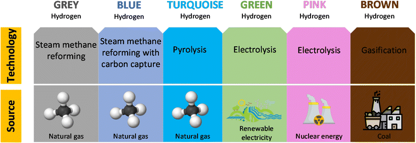 | ||
| Fig. 1 The spectral colors of hydrogen based on the production method (modified from Renewable Energy Agency, 2020).9 | ||
Life cycle assessment (LCA) is a powerful tool used to evaluate the environmental impact potential of a product or system throughout its life cycle. This assessment encompasses all stages, starting from the extraction of raw materials in the upstream processes, through the manufacturing, distribution, and use of the product, and finally to its end-of-life phase in the downstream processes. By conducting an LCA, we can obtain comprehensive results that quantify the emissions released into the air, water, and soil, originating from significant inputs from the environment.10
A number of studies have used LCA to examine the environmental impact of hydrogen. Howarth & Jacobson (2021) conducted a life cycle assessment (LCA) of blue hydrogen, although they did not include the environmental impact of natural gas extraction and transportation from the source because the aim of the study was to compare blue hydrogen to grey hydrogen.11 Osman et al. (2021) compared blue hydrogen to green hydrogen. In their LCA, they assumed that carbon captured from blue hydrogen is 100% from the process and did not consider emissions from the transportation of fossil feedstock (natural gas).12 Hermesmann & Müller (2022) conducted an LCA for grey, blue, turquoise, and green hydrogen.13 This work considered upstream emissions of natural gas from the natural gas grid for the respective countries similar to Howarth & Jacobson (2021).11
The present work contributes to the field in three main ways. Firstly, it conducts an LCA of hydrogen production using the LNG route for grey and blue hydrogen, which encompasses all stages of the LNG supply chain, including liquefaction, compression, and regasification. Secondly, it performs an LCA of turquoise hydrogen, comparing the natural gas input from both pipeline and LNG routes to the conventional method of hydrogen production. Finally, it calculates the global warming potential of blue and turquoise hydrogen over 20 and 100 years to compare it with grey hydrogen.
2. Materials and methods
The environmental impact of hydrogen production technologies is assessed in this work using the LCA method. LCA is defined as the systematic analysis of the potential environmental impacts of a product or service throughout its life cycle (ISO standard 14040-14044:2006), including production, distribution, use, storage, recycling, and end-of-life.14 The guidelines and requirements provided in ISO 14040 and ISO 14044 ensure that the LCA approach is comprehensive, compatible, and clear.15 Moreover, the use of ISO standards ensures that studies by different research groups are comparable. The LCA procedure is divided into four phases: goal and scope, life cycle inventory (LCI) analysis, life cycle impact assessment (LCIA) and interpretation.15 This procedure creates a rational basis for decision-making, which confirms the comparability of different processes through quantified environmental impacts and serves to identify potential areas for improvement.The LCA in this study is modelled using Sphera Gabi software version 10.5.1.124, and the inventory in the Gabi software has the database from 1992 to 2021. The electricity usage for grey, blue, and turquoise hydrogen production is from the Finnish 2030 electricity mix and green hydrogen production uses solely solar and wind electricity from Finland. The 2030 electricity mix was chosen for this study because Finland's National Energy and Climate Plan 2021–2030 foresees a 50% share of energy from renewable sources and the complete phasing out of coal usage as a source of energy along with a 39% emission reduction target.16
2.1. Goal and scope
The aim of this study is to assess and compare the environmental impacts of hydrogen production, specifically examining scenarios where natural gas is sourced from Russia via pipelines and LNG is sourced from the USA. This study examines four different processes of hydrogen production: (1) SMR (grey hydrogen), (2) SMR-CCS (blue hydrogen), (3) TDM (turquoise hydrogen) and (4) PEM electrolysis (green hydrogen). The assessment of green hydrogen is for the same output as the other forms of hydrogen. It is assumed that the required electricity is the 2030 electricity mix grid power. The current research builds on findings of a previous study conducted as part of a master's thesis.17 The scope of the LCA is from “cradle to gate”, that is, from the extraction of raw materials to the factory gate. The remaining phases of the life cycle, such as the transport, storage and utilization of hydrogen, and the associated environmental impacts are excluded since they do not depend on the hydrogen production technology used.The outcome of the product systems under consideration is quantified using a functional unit, which enables the comparison between scenarios. The selected functional unit is 1 kg of hydrogen available at the gate of the production site. All input and output data for each product system are normalized in the mathematical sense to this reference.
Climate change has been chosen as the impact category of interest as done in previous studies by Howarth & Jacobson (2021) and Bauer et al. (2022) because hydrogen is believed to play a crucial role in achieving a low-carbon energy system.11,18 To demonstrate short-term and long-term climate impacts, both the 100-year horizon global warming potential and the 20-year horizon global warming potential, GWP100 and GWP20, respectively, have been included and the unit for calculation is taken as kg CO2 eq. per kg H2.
2.2. System boundaries
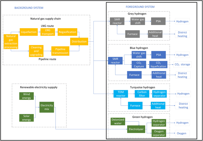
The studied system boundary for the LCA of hydrogen production from natural gas for the SMR, SMR-CCS and TDM processes and from renewable electricity in the case of the electrolysis process is shown in Fig. 2. Natural gas extraction and processing, transport, and emissions are included in the system boundary. Two possibilities for natural gas input are studied, namely, the pipeline route from Russia and the LNG route from the USA. Fugitive emissions from natural gas transmission as results of leaks are included in this study, but emissions resulting from accidental explosions or maintenance work on natural gas pipelines are not included. Heat and energy to liquefy natural gas and regasification for use are considered for the LNG route, which provides more realistic results in the case of grey hydrogen.In life cycle assessment, it is possible to apply multiple functions to a system so that the valuable by-product of the system can be used to reduce the burden of another system. For example, the additional heat generated by an SMR plant can be used to generate steam and used in district heating, and oxygen from PEM electrolysis can be used as a valuable product. Therefore, it is rational to design the LCA model in such a way that the valuable by-products are exploited, and some burdens of other systems are avoided, thus reducing the total environmental impact.
2.3. Scenario analysis
This study evaluates four different scenarios for hydrogen production: grey hydrogen; blue hydrogen; turquoise hydrogen; and green hydrogen. Within grey, blue, and turquoise hydrogen, there are sub-scenarios referring to the natural gas being supplied either via pipelines or LNG, respectively.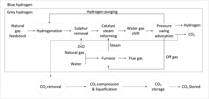 | ||
| Fig. 3 Grey hydrogen (SMR) and blue hydrogen (SMR-CCS) production (modified from Petrescu et al., 2014).19 | ||
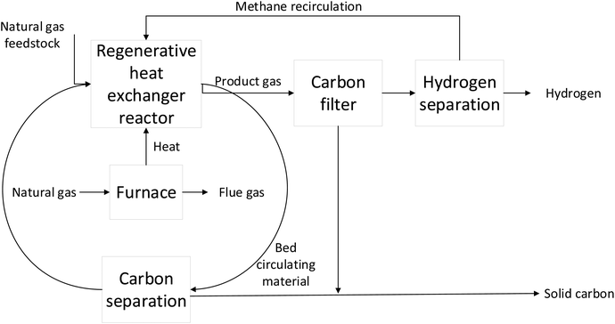 | ||
| Fig. 4 Turquoise hydrogen (TDM) production (modified from Keipi et al., 2018).25 | ||
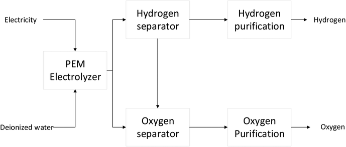 | ||
| Fig. 5 Overview of green hydrogen (PEM electrolyzer) production (modified from Hermesmann & Müller, 2022).13,28 | ||
2.4. Inventory analysis
All material and energy flows within and across the boundaries of the examined product system are quantified in the inventory analysis phase. The resulting data set is called the Life Cycle Inventory (LCI). In this study, data from the GaBi inventory were used in the first instance, and if the data were not present in the GaBi database, then the data from scientific articles were used. The inventory database for Gabi can be found in the ESI in background data Table S6† and is also available on the Sphera website.29 The infrastructure material and energy flows such as manufacturing of equipment were considered for grey, blue, and green hydrogen. Infrastructure emissions were not considered for turquoise hydrogen due to a lack of data. The existing infrastructure for pipelines and the LNG route was used in the analysis. The LCI data for the hydrogen production processes examined are provided in the ESI.†2.5. Sensitivity analysis
The LCA outcome may be affected by modelling assumption and choices, particularly the system boundaries and the input parameters which can be uncertain.30 Therefore sensitivity analysis should be used to assess the assumptions and choices of the model as well as the robustness of the outcome and its sensitivity to various factors.31In this work, perturbation analysis was used to identify the effects that changes in parameters have on the overall net result. Perturbation analysis shows the most sensitive parameters on the basis of the sensitivity ratio (SR).32 The impact of variations in each SR value on the overall result can be determined through the following equation:  .33 According to Heijungs & Kleijn (2001), parameters with SR values (as an absolute value) greater than 0.8 are important, that is, the parameter has a significant effect on the LCA outcome.34 If the absolute value of the SR value is higher than 1.0, the parameter is seen as particularly important. However, if the SR value of a parameter is less than 0.2, it has minimal influence on the overall results.
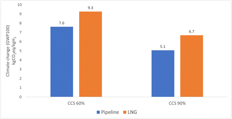
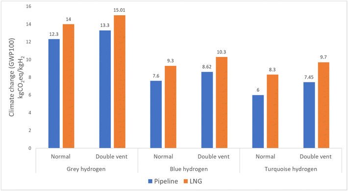
Besides the perturbation analysis, the impact of selected modelling choices on the net results was also analyzed. In the first analysis of modelling choices, electricity, which was assumed to be supplied by the 2030 electricity grid mix for grey, blue, and turquoise hydrogen, was changed to 100% wind power. The electricity consumption includes consumption for natural gas extraction, natural gas transmission through both routes, the hydrogen production process, the carbon capture process in the case of blue hydrogen, and hydrogen storage. In the second analysis of modelling, the capture rate of carbon dioxide from the SMR process in blue hydrogen production is 99%. However, since natural gas is burned in the combustion chamber to generate high temperature steam for the SMR process and carbon dioxide is not currently captured from this stage, the overall capture rate is 60%. A sensitivity analysis was conducted to consider the capture of carbon dioxide also from the combustion chamber, which would increase the overall carbon dioxide capture rate to 90%. The third sensitivity analysis involved examination of the transmission emissions. The assumption in the LCA is that 1% of the produced and transmitted natural gas is vented during the transmission of natural gas through the pipeline route. In this sensitivity analysis, we assumed that the venting of natural gas is twice the assumed data. In the case of the LNG route, we assumed 1% natural gas venting during the regasification process for sensitivity analysis.
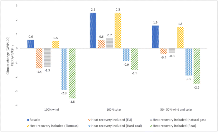
In sensitivity analysis for green hydrogen, the first sensitivity analysis involves changing the emission factor of solar and wind power production for a 1 kW h output. According to De Wild-Scholten (2013), solar energy emits 20–81 g CO2 eq. per kW h.35 However, Kamal et al. (2020) presented lower emissions of 35–40 g CO2 eq. per kW h for solar energy, and only 11 g CO2 eq. per kW h for wind energy.36 Meanwhile, Prakash & Krishnan Bhat (2009) reported emissions of 16–40 g CO2 eq. per kW h from wind turbines for 1 kW h of energy.37 The second sensitivity analysis considered the utilization of waste heat from the electrolyzer to avoid the impact of heat production for district heating purposes from different fuels. The third sensitivity analysis included the utilisation of oxygen in the combustion process to avoid the impact of oxygen production.
3. Results and discussion
3.1. Life cycle impact assessment results
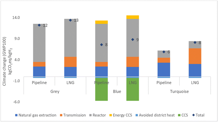
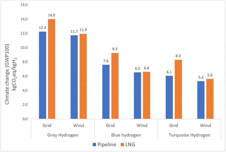
The LCIA results of the studied hydrogen production methods are presented in Fig. 6. Detailed results can be found in the ESI† in the Results section. Fig. 7 displays the outcome for green hydrogen, which is derived from renewable energy sources. In contrast, the outcomes for grey, blue, and turquoise hydrogen depend on fossil fuels, and therefore their results are presented individually.The results for grey, blue, and turquoise hydrogen differ for the pipeline route and the LNG route, with the LNG route showing higher emissions for all three types of hydrogen. Specifically, grey hydrogen yields 13% higher emissions for the LNG route of 13.9 kg CO2 eq. per kg H2 compared to 12.3 kg CO2 eq. per kg H2 for the pipeline route. Blue hydrogen yields lower emission than grey hydrogen due to the use of carbon capture technology, with a result of 7.6 kg CO2 eq. per kg H2 for the pipeline route and 9.3 kg CO2 eq. per kg H2 for the LNG route. Turquoise hydrogen, which requires more heat energy from burning natural gas in the combustion chamber of the TDM reactor but produces lower CO2 emission from the reactor due to the production of solid carbon, yields the lowest results of 6.1 kg CO2 eq. per kg H2 for the pipeline route and 8.3 kg CO2 eq. per kg H2 for the LNG route. The reduction in emissions from blue and turquoise hydrogen is significant, with blue hydrogen emission being around 25–38% and turquoise hydrogen emission being 35–54% lower than that of grey hydrogen. The detailed breakdown of emission results for grey, blue, turquoise, and green hydrogen can be found in the ESI in the Results section (Table S8†). Furthermore, the carbon product from TDM could replace carbon black. Global demand for carbon black is 15 Mt a−1 globally and producing this by TDM would at the same time produce 4.6 Mt a−1 hydrogen, which is roughly 13% of the hydrogen produced to date from natural gas (47% of 75 Mt a−1). It can be seen in the ESI in the carbon black section (Tables S17–19†).
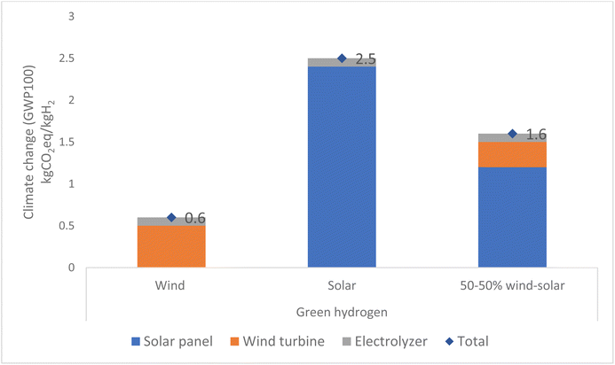
Results for the production of green hydrogen demonstrate that connecting the electricity grid solely to wind energy results in a total emission of 0.6 kg CO2 eq. per kg H2. Conversely, connecting the electricity grid only to solar energy results in a higher total emission of 2.5 kg CO2 eq. per kg H2. When the electricity grid is connected to both solar and wind energy in a 50![[thin space (1/6-em)]](https://www.rsc.org/images/entities/char_2009.gif) :
:![[thin space (1/6-em)]](https://www.rsc.org/images/entities/char_2009.gif) 50 ratio, most emissions come from solar energy, which emits 1.2 kg CO2 eq. per kg H2. Emissions from wind energy are lower, of 0.3 kg CO2 eq. per kg H2, and only a small amount comes from manufacturing of the electrolyser. The total emission for this is 1.5 kg CO2 eq. per kg H2, as illustrated in Fig. 7. Green hydrogen provides emission reduction of 80–95% compared to grey hydrogen.
50 ratio, most emissions come from solar energy, which emits 1.2 kg CO2 eq. per kg H2. Emissions from wind energy are lower, of 0.3 kg CO2 eq. per kg H2, and only a small amount comes from manufacturing of the electrolyser. The total emission for this is 1.5 kg CO2 eq. per kg H2, as illustrated in Fig. 7. Green hydrogen provides emission reduction of 80–95% compared to grey hydrogen.
As per the renewable energy directive (RED) II, the production of hydrogen as a renewable fuel of non-biological origin (RFNBO) should have production emissions lower than 3.38 kg CO2 eq. per kg H2 or achieve a 70% reduction compared to fossil fuels. According to the results, green hydrogen can meet this requirement, whereas blue hydrogen and turquoise hydrogen cannot meet this requirement unless the carbon produced is sequestered.
3.2. Comparison of 100-year GWP and 20-year GWP
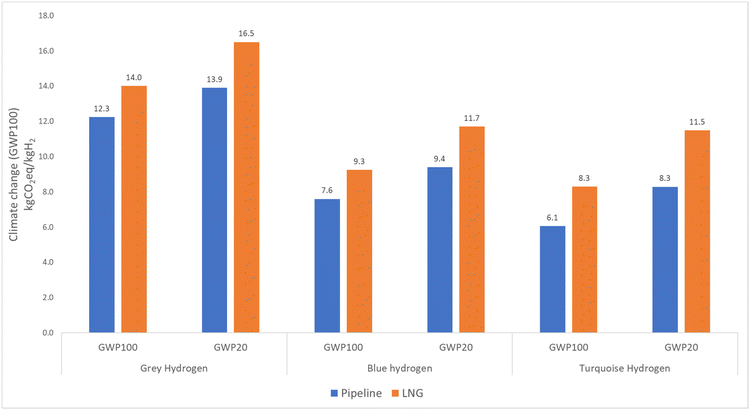
Since the study focuses on climate impact, it was necessary to select an appropriate time frame. Traditionally, studies on climate impact have used a time span of 100 years. However, in this instance, it is sensible to consider the impact over a 20-year period to highlight the role of methane in hydrogen production over a shorter time period.11 It is important to note that the Intergovernmental Panel on Climate Change (IPCC) has identified methane as a greenhouse gas that has 86 times more global warming impact than CO2 over a 20-year time span. To prevent a significant global temperature increase and its damaging consequences, it is essential to address climate change mitigation within the next few decades.38GWP20 shows a 12–25% higher value than GWP100 for grey, blue, and turquoise hydrogen, as shown in Fig. 8. This result is attributable to methane leaks that occur during natural gas extraction and transmission. Specifically, in the case of pipeline routes, methane is often emitted through vents from the pipeline, whereas in the case of LNG routes, leaks occur during the transportation, liquefaction, and regasification processes. The LNG route has about 18% more climate impact for GWP100 and 23% more climate impact for GWP20 than the natural gas pipeline route for all hydrogen production technologies. The difference between GWP100 and GWP20 is about 16–28% for the LNG route.
The use of GWP20 does not have a significant impact on the result for green hydrogen because its production does not involve the intake of natural gas as it is solely reliant on renewable energy sources.
3.3. Sensitivity analysis
The sensitivity ratio (SR) values of the sensitivity analyses are compiled in Table 1. In the case of grey hydrogen, compressing and transmitting natural gas through pipelines has a minor impact (SR 0.05–0.16 and SR 0.01–0.09, respectively), while the liquefaction and regasification stages of the LNG route have a moderate impact (SR 0.56–0.74 and 0.44–0.66, respectively). For the SMR reactor, the carbon dioxide output has the most impact when natural gas is sourced through the pipeline route (SR 0.64), while the heat output has the most impact when LNG is used (SR 0.68). None of the SR values show that there is an individual parameter that had a major impact on the overall results (SR > 1). The total detailed results of the sensitivity analysis are included in the ESI.†| Grey hydrogen | Blue hydrogen | Turquoise hydrogen | |
|---|---|---|---|
| Compression | |||
| Natural gas input | 0.06 | 0.11 | 0.16 |
| Electricity output | 0.16 | 0.25 | 0.1 |
| CO2 output | 0.05 | 0.13 | 0.18 |
| Natural gas pipeline | |||
| Electricity input | 0.03 | 0.4 | 0.19 |
| Natural gas input | 0.07 | 0.19 | 0.52 |
| Natural gas output | 0.09 | 0.15 | 0.08 |
| Natural gas vent | 0.01 | 0.01 | 0.08 |
| Liquefication | |||
| Electricity input | 0.56 | 1.01 | 1.14 |
| Natural gas input | 0.56 | 1.02 | 1.18 |
| LNG output | 0.74 | 1.3 | 1.6 |
| Regasification | |||
| Heat input | 0.61 | 1.1 | 1.29 |
| Natural gas input | 0.44 | 1.17 | 1.4 |
| Natural gas output | 0.66 | 0.87 | 0.92 |
| CO 2 captured | |||
| CO2 input | — | 1.59 | — |
| Electricity input | — | 1.13 | — |
| CO2 captured | — | 1.14 | — |
| CO2 emission | — | 0.79 | — |
| CO 2 liquefied | |||
| CO2 input | — | 1.2 | — |
| CO2 output | — | 1.16 | — |
| Electricity input | — | 1.15 | — |
| CO 2 injection | |||
| CO2 input | — | 1.14 | — |
| Electricity input | — | 1.17 | — |
| SMR reactor (pipeline) | |||
| CO2 output | 0.64 | 0.42 | — |
| Heat output | 0.11 | 0.18 | — |
| Natural gas input (pipe) | 0.18 | 0.11 | — |
| SMR reactor (LNG) | |||
| CO2 output | 0.07 | 0.67 | — |
| Heat output | 0.68 | 1.18 | — |
| Natural gas input (LNG) | 0.36 | 0.961 | — |
| TDM reactor pipeline | |||
| CO2 emission | — | — | 0.21 |
| CO2 output (solid) | — | — | 0.25 |
| Heat output | — | — | 0.43 |
| Natural gas input pipeline | — | — | 0.21 |
| TDM reactor LNG | |||
| CO2 emission | — | — | 1.02 |
| CO2 output | — | — | 1.64 |
| Heat output | — | — | 1.61 |
In the case of blue hydrogen, the SR values vary depending on the natural gas process. For natural gas compression, the impact is relatively low (SR 0.1–0.25), while for natural gas pipeline transmission, the impact is moderate (SR up to 0.4). However, for the LNG route, the liquefaction and regasification processes have a higher impact (SR > 1). The most sensitive parameter is related to carbon dioxide capture, compression, and storage. These processes have the highest SR values of all the processes considered. The impact of the SMR reactor also varies depending on the route. When connected to the pipeline route, the impact is relatively lower (SR 0.01–0.42), while when connected to the LNG route, the impact is major (SR 0.67–1.18).
For turquoise hydrogen, the data for SR value indicate that connecting the TDM reactor to the pipeline route results in a lower impact (SR 0.21–0.43). Additionally, the natural gas pipeline and compressor have a lower impact as well (SR 0.08–0.52 and 0.1–0.18, respectively). However, when the TDM reactor is connected to the LNG route, the impacts are major (SR 1.0–1.64) because the LNG route, which involves liquefaction and regasification, has a higher impact as well (SR 1.1–1.6 and SR 0.9–1.4, respectively).
Besides perturbation analysis, the impact of main modelling choices was included in the sensitivity analysis. Modelling choices selected for sensitivity analysis included electricity source, carbon dioxide capture rate and the venting of natural gas. In the case of grey, blue, and turquoise hydrogen, the change of electricity source from the 2030 electricity grid to 100% wind energy leads to a reduction in GWP100 of around 12% for the pipeline route and 26% for the LNG route, as shown in Fig. 9. Detailed results can been in the ESI.† The impact of capturing carbon dioxide from the combustion chamber as well as the reactor in the case of blue hydrogen can be observed from Fig. 10. The results show 33% reduction in emissions for the pipeline route and 28% reduction for the LNG route. The results in Fig. 11 show that when venting is doubled compared to the actual assumption (1% of produced natural gas), the results increase from 8% to 20% for the pipeline route and from 7% to 15% for the LNG route for grey, blue, and turquoise hydrogen.
In the case of green hydrogen, the emission factor of solar and wind electricity and the utilization of excess heat and oxygen from electrolysis were included in the sensitivity analysis. Fig. 12 presents a comparison of climate change results for green hydrogen production including the results of the present study and results utilizing the average or maximum emission factor found from the literature for solar and wind electricity production. Interestingly, our results for solar energy-based hydrogen production are consistent with the average value found in the literature. However, there are notable discrepancies between our results and the literature values for wind energy, indicating significant variability in emission data.
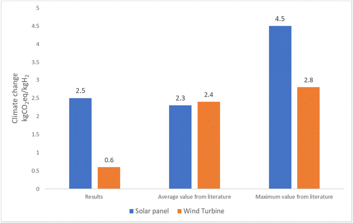 | ||
| Fig. 12 Comparison of green hydrogen result of GABI data with previous studies of solar and wind energy emission. | ||
Taking into account the utilization of excess heat from the electrolyzer and the oxygen produced reduces the net climate change impact. Fig. 13 summarizes the impact on net climate change results when considering utilization of waste heat from an electrolyzer to substitute for district heating from various fuels. Based on the results, it is possible to achieve even a negative carbon footprint. The most favorable outcome is observed when green hydrogen production is powered entirely by wind turbines and the waste heat is utilized for district heating sourced from peat thermal energy. Fig. 14, it can be seen that for green hydrogen, the utilization of oxygen from the electrolyzer results in a 30% decrease in impact when powered by solar energy and a significant 60% reduction when powered by wind energy.
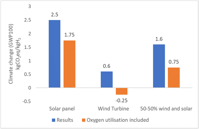 | ||
| Fig. 14 Comparison of green hydrogen results of GABI data with oxygen utilization from the electrolyzer. | ||
3.4. Comparison to earlier studies
In previous studies by Hermesmann & Müller (2022),13 Collodi et al. (2017),39 Al-Qahtani et al. (2021),40 Salkuyeh et al. (2017),41 Bauer et al. (2022),18 Cetinkaya et al. (2012),42 and Soltani et al. (2014),43 it was found that GHG emissions from grey hydrogen plants ranged from 7 to 11 kg CO2 eq. per kg H2. In the current study, the results were higher due to the inclusion of natural gas extraction and transmission emissions. When transporting natural gas via pipelines, there are two types of emissions to consider: those resulting from compressing and transporting the gas and those resulting from unintended events such as leaks or maintenance. Taking both types of emissions into account provides a more accurate assessment.In the study by Howarth & Jacobson (2021),11 it was found that for blue hydrogen, the total carbon dioxide emissions were only 9–12% lower than for grey hydrogen for GWP20 years. In the current study, however, when natural gas came from the pipeline route, the total carbon dioxide emissions for blue hydrogen were found to be 32% lower than those for grey hydrogen for GWP20 years. The lower emission values are because 60% of the carbon dioxide is captured from the SMR process, and fugitive emissions resulting from methane leaks are negligible in the SMR process.
The study conducted by Cetinkaya et al. (2012)42 revealed that the production of hydrogen through wind energy resulted in emissions of 0.9 kg CO2 eq. per kg H2, while solar energy resulted in emissions of 2.4 kg CO2 eq. per kg H2, which aligns closely with our findings. A study conducted by Ji & Wang (2021)44 revealed that hydrogen produced through wind energy had greenhouse gas emissions of 1.8 kg CO2 eq. per kg H2, while solar energy resulted in emissions of 1.82 kg CO2 eq. per kg H2. Similarly, a study by Aydin & Dincer (2022)45 reported emissions from renewable energy sources such as wind and solar energy to be around 1.6 kg CO2 eq. per kg H2. These results are in line with our study's findings on green hydrogen.
4. Conclusion
Despite the use of hydrogen having a zero-carbon footprint, the production of hydrogen generates a significant amount of CO2 emission when derived from fossil fuels. The LCA in this study was performed for four different hydrogen production methods to identify the environmental impact of the most approachable and common forms of hydrogen production, namely, steam methane reforming (SMR), steam methane reforming coupled with carbon capture and storage (SMR-CCS), thermal methane decomposition (TDM) and water electrolysis with polymer electrolyte membrane (PEM) electrolysers.In order to accurately assess the sustainability of blue and turquoise hydrogen in comparison with green hydrogen, it is crucial to consider the upstream emissions associated with natural gas and liquefied natural gas (LNG) extraction, compression, liquefaction, transmission, and regasification. These upstream emissions alone can surpass the overall environmental impact of green hydrogen production. Even utilizing a grid mix electricity with an emission limit of 105 g CO2 eq. per kW h, Finland's average specific emission of grid electricity from 2019 to 2021 was only 77 g CO2 eq. per kW h,46 making green hydrogen production with a small percentage of fossil fuel-based electricity still more environmentally friendly than blue or turquoise hydrogen.
The natural gas pipeline transportation distance had only minor impact in the case of production of grey, blue, and turquoise hydrogen. The LNG route has greater environmental impacts than the natural gas pipeline route for grey, blue, and turquoise hydrogen. Hydrogen production through the TDM (turquoise hydrogen) process has less climate impact than that through the traditional SMR (grey hydrogen) and SMR-CCS (blue hydrogen) processes. The impact will be lower if the carbon by-product is sequestrated. However, this technology is in the early stages of development, and the use of solid carbon has not yet been fully explored. Additionally, emissions of turquoise hydrogen production can also be reduced if a renewable methane source is used, for example, biogas or methane produced from biomass.
While the green hydrogen path seems preferable in the future, there might be a need for bridging technology or a backup plan for future fluctuating renewable energy. Blue and turquoise hydrogen production could be a middle-term solution until the long-term solution is achieved, that is, the production of 100 percent green sustainable hydrogen. Existing SMR plants could be retrofitted to add CCS to produce blue hydrogen, which would result in a reduction in climate change impact of 25–40% compared to grey hydrogen. Besides the CCS technology, storage locations that are suitable for the captured CO2 are necessary. Ultimately, the outcomes suggest that only green hydrogen aligns with the RED II climate impact limit for hydrogen production.
Conflicts of interest
There are no conflicts to declare.Acknowledgements
The research was partially funded by the Hygcel project co-financed by the Business Finland.References
- The Future of Hydrogen – Analysis – IEA. https://www.iea.org/reports/the-future-of-hydrogen (accessed 2023-06-13).
- Intenrational Energy Agency, Hydrogen - Fuels & Technologies - IEA, IEA, Hydrogen, Paris, 2021, https://www.iea.org/fuels-and-technologies/hydrogen (accessed 2022-11-15) Search PubMed.
- A. Kovač, M. Paranos and D. Marciuš, Hydrogen in Energy Transition: A Review, Int. J. Hydrogen Energy, 2021, 46(16), 10016–10035, DOI:10.1016/J.IJHYDENE.2020.11.256.
- T. Van de Graaf, I. Overland, D. Scholten and K. Westphaal, The New Oil? The Geopolitics and International Governance of Hydrogen, Energy Res. Soc. Sci., 2020, 70, 101667, DOI:10.1016/j.erss.2020.101667.
- M. Noussan, P. P. Raimondi, R. Scita and M. Hafner, The Role of Green and Blue Hydrogen in the Energy Transition—A Technological and Geopolitical Perspective, Sustainability, 2020, 13(1), 298, DOI:10.3390/SU13010298.
- J. Diab, L. Fulcheri, V. Hessel, V. Rohani and M. Frenklach, Why Turquoise Hydrogen Will Be a Game Changer for the Energy Transition, Int. J. Hydrogen Energy, 2022, 47(61), 25831–25848, DOI:10.1016/J.IJHYDENE.2022.05.299.
- A. M. Oliveira, R. R. Beswick and Y. Yan, A Green Hydrogen Economy for a Renewable Energy Society, Curr. Opin. Chem. Eng., 2021, 33, 100701, DOI:10.1016/J.COCHE.2021.100701.
- S. Sebbahi, N. Nabil, A. Alaoui-Belghiti, S. Laasri, S. Rachidi and A. Hajjaji, Assessment of the Three Most Developed Water Electrolysis Technologies: Alkaline Water Electrolysis, Proton Exchange Membrane and Solid-Oxide Electrolysis, Mater. Today: Proc., 2022, 66, 140–145, DOI:10.1016/J.MATPR.2022.04.264.
- Renewable Energy Agency, I., Green Hydrogen: A Guide to Policy Making, 2020 Search PubMed.
- What is Life Cycle Assessment (LCA)? | Sphera. https://sphera.com/glossary/what-is-a-life-cycle-assessment-lca/ (accessed 2023-06-13).
- R. W. Howarth and M. Z. Jacobson, How Green Is Blue Hydrogen?, Energy Sci. Eng., 2021, 9(10), 1676–1687, DOI:10.1002/ESE3.956.
- A. I. Osman, N. Mehta, A. M. Elgarahy, M. Hefny, A. Al-Hinai, A. H. Al-Muhtaseb and D. W. Rooney, Hydrogen Production, Storage, Utilisation and Environmental Impacts: A Review, Environ. Chem. Lett., 2021, 20(1), 153–188, DOI:10.1007/S10311-021-01322-8.
- M. Hermesmann and T. E. Müller, Green, Turquoise, Blue, or Grey? Environmentally Friendly Hydrogen Production in Transforming Energy Systems, Prog. Energy Combust. Sci., 2022, 90, 100996, DOI:10.1016/J.PECS.2022.100996.
- Life Cycle Assessment (LCA): A Guide to Best Practice - Walter Klöpffer, Birgit Grahl - Google Books. https://books.google.fi/books?hl=en&lr=&id=NkRsAwAAQBAJ&oi=fnd&pg=PT9&ots=HgAGx2yatm&sig=uBIZP7lcg09PgxwfNbC0juEPEeY&redir_esc=y#v=onepage&q&f=false (accessed 2022-04-26).
- ISO - ISO 14044:2006 - Environmental management—Life cycle assessment—Requirements and guidelines. https://www.iso.org/standard/38498.html (accessed 2022-04-26).
- P. Toivanen, P. Lehtonen, P. Aalto, T. Björkqvist, P. Jãrventausta, S. Kilpelãinen, M. Kojo and F. Myllãri, Finland’s Energy System for 2030 as Envisaged by Expert Stakeholders, Energy Strategy Rev., 2017, 18, 150–156, DOI:10.1016/j.esr.2017.09.007.
- G. H. Patel, Comparision of the Climate Impacts of Different Hydrogen Production Routes in Finland, 2022 Search PubMed.
- C. Bauer, K. Treyer, C. Antonini, J. Bergerson, M. Gazzani, E. Gencer, J. Gibbins, M. Mazzotti, S. T. McCoy, R. McKenna, R. Pietzcker, A. P. Ravikumar, M. C. Romano, F. Ueckerdt, J. Vente and M. van der Spek, On the Climate Impacts of Blue Hydrogen Production, Sustainable Energy Fuels, 2022, 6(1), 66–75, 10.1039/d1se01508g.
- L. Petrescu, C. R. Müller and C. C. Cormos, Life Cycle Assessment of Natural Gas-Based Chemical Looping for Hydrogen Production, in Energy Procedia, Elsevier Ltd, 2014, vol. 63, pp. 7408–7420. DOI:10.1016/j.egypro.2014.11.777.
- J. C. Molburg and R. D. Doctor, Hydrogen from Steam-Methane Reforming with CO2 Capture, 20th Annual International Pittsburgh Coal Conference, 2003 Search PubMed.
- Y. A. Alhamdani, M. H. Hassim, R. T. L. Ng and M. Hurme, The Estimation of Fugitive Gas Emissions from Hydrogen Production by Natural Gas Steam Reforming, Int. J. Hydrogen Energy, 2017, 42(14), 9342–9351, DOI:10.1016/j.ijhydene.2016.07.274.
- J. Dufour, D. P. Serrano, J. L. Gálvez, J. Moreno and C. García, Life Cycle Assessment of Processes for Hydrogen Production. Environmental Feasibility and Reduction of Greenhouse Gases Emissions, Int. J. Hydrogen Energy, 2009, 34(3), 1370–1376, DOI:10.1016/J.IJHYDENE.2008.11.053.
- E. Välimäki, L. Yli-Varo, H. Romar and U. Lassi, Carbons Formed in Methane Thermal and Thermocatalytic Decomposition Processes: Properties and Applications, 2021, 750, DOI:10.3390/c7030050.
- N. Sánchez-Bastardo, R. Schlögl and H. Ruland, Methane Pyrolysis for Zero-Emission Hydrogen Production: A Potential Bridge Technology from Fossil Fuels to a Renewable and Sustainable Hydrogen Economy, Ind. Eng. Chem. Res., 2021, 60(32), 11855–11881, DOI:10.1021/ACS.IECR.1C01679/ASSET/IMAGES/LARGE/IE1C01679_0008.JPEG.
- T. Keipi, H. Tolvanen and J. Konttinen, Economic Analysis of Hydrogen Production by Methane Thermal Decomposition: Comparison to Competing Technologies, Energy Convers. Manage., 2018, 159, 264–273, DOI:10.1016/j.enconman.2017.12.063.
- Department of Energy. https://www.energy.gov/eere/articles/hydrogen-clean-flexible-energy-https://www.nationalgrid.com/stories/energy-explained/hydrogen-colour-spectrum (accessed 2022-04-14).
- K. K. Wu, Y. C. Chang, C. H. Chen and Y. D. Chen, High-Efficiency Combustion of Natural Gas with 21–30% Oxygen-Enriched Air, Fuel, 2010, 89(9), 2455–2462, DOI:10.1016/J.FUEL.2010.02.002.
- M. Hermesmann and T. E. Müller, Green, Turquoise, Blue, or Grey? Environmentally Friendly Hydrogen Production in Transforming Energy Systems, in Progress in Energy and Combustion Science, Elsevier Ltd, 2022. DOI:10.1016/j.pecs.2022.100996.
- Product Sustainability Data Search | Sphera (GaBi). https://sphera.com/product-sustainability-gabi-data-search/ (accessed 2023-11-10).
- M. M. H. Khan, J. Havukainen, A. Niini, V. Leminen and M. Horttanainen, Consequential Life-Cycle Assessment of Treatment Options for Repulping Reject from Liquid Packaging Board Waste Treatment, Waste Manage., 2023, 155, 348–356, DOI:10.1016/J.WASMAN.2022.10.026.
- M. Abdulkareem, J. Havukainen, J. Nuortila-Jokinen and M. Horttanainen, Life Cycle Assessment of a Low-Height Noise Barrier for Railway Traffic Noise, J. Cleaner Prod., 2021, 323, 129169, DOI:10.1016/J.JCLEPRO.2021.129169.
- J. Clavreul, D. Guyonnet and T. H. Christensen, Quantifying Uncertainty in LCA-Modelling of Waste Management Systems, Waste Manage., 2012, 32(12), 2482–2495, DOI:10.1016/J.WASMAN.2012.07.008.
- M. Liikanen, J. Havukainen, M. Hupponen and M. Horttanainen, Influence of Different Factors in the Life Cycle Assessment of Mixed Municipal Solid Waste Management Systems – A Comparison of Case Studies in Finland and China, J. Cleaner Prod., 2017, 154, 389–400, DOI:10.1016/J.JCLEPRO.2017.04.023.
- R. Heijungs and R. Kleijn, Numerical Approaches towards Life Cycle Interpretation Five Examples, Int. J. Life Cycle Assess., 2001, 6(3), 141–148, DOI:10.1007/BF02978732/METRICS.
- M. J. De Wild-Scholten, Energy Payback Time and Carbon Footprint of Commercial Photovoltaic Systems, Sol. Energy Mater. Sol. Cells, 2013, 119, 296–305, DOI:10.1016/J.SOLMAT.2013.08.037.
- M. Kamal, H. Rabaia, M. A. Abdelkareem, E. T. Sayed, K. Elsaid, K.-J. Chae, T. Wilberforce and A. G. Olabi, Environmental Impacts of Solar Energy Systems: A Review, 2020. DOI:10.1016/j.scitotenv.2020.141989.
- Varun, R. Prakash and I. Krishnan Bhat, Energy, Economics and Environmental Impacts of Renewable Energy Systems, Renewable Sustainable Energy Rev., 2009, 13, 2716–2721, DOI:10.1016/j.rser.2009.05.007.
- P. Balcombe, J. F. Speirs, N. P. Brandon and A. D. Hawkes, Methane Emissions: Choosing the Right Climate Metric and Time Horizon, Environ. Sci.: Processes Impacts, 2018, 20(10), 1323–1339, 10.1039/C8EM00414E.
- G. Collodi, G. Azzaro, N. Ferrari and S. Santos, Techno-Economic Evaluation of Deploying CCS in SMR Based Merchant H2 Production with NG as Feedstock and Fuel, in Energy Procedia, Elsevier Ltd, 2017, vol. 114, pp. 2690–2712. DOI:10.1016/j.egypro.2017.03.1533.
- A. Al-Qahtani, B. Parkinson, K. Hellgardt, N. Shah and G. Guillen-Gosalbez, Uncovering the True Cost of Hydrogen Production Routes Using Life Cycle Monetisation, Appl. Energy, 2021, 281, 115958, DOI:10.1016/J.APENERGY.2020.115958.
- Y. K. Salkuyeh, B. A. Saville and H. L. Maclean, Techno-Economic Analysis and Life Cycle Assessment of Hydrogen Production from Natural Gas Using Current and Emerging Technologies, 2017, DOI:10.1016/j.ijhydene.2017.05.219.
- E. Cetinkaya, I. Dincer and G. F. Naterer, Life Cycle Assessment of Various Hydrogen Production Methods, Int. J. Hydrogen Energy, 2012, 37(3), 2071–2080, DOI:10.1016/J.IJHYDENE.2011.10.064.
- R. Soltani, M. A. Rosen and I. Dincer, Assessment of CO2 Capture Options from Various Points in Steam Methane Reforming for Hydrogen Production, Int. J. Hydrogen Energy, 2014, 39(35), 20266–20275, DOI:10.1016/j.ijhydene.2014.09.161.
- M. Ji and J. Wang, Review and Comparison of Various Hydrogen Production Methods Based on Costs and Life Cycle Impact Assessment Indicators, Int. J. Hydrogen Energy, 2021, 46(78), 38612–38635, DOI:10.1016/J.IJHYDENE.2021.09.142.
- M. I. Aydin and I. Dincer, An Assessment Study on Various Clean Hydrogen Production Methods, Energy, 2022, 245, 123090, DOI:10.1016/J.ENERGY.2021.123090.
- Tilastokeskus - 12 Energia ja päästöt. https://pxhopea2.stat.fi/sahkoiset_julkaisut/energia2022/html/suom0011.htm (accessed 2023-04-17).
Footnote |
| † Electronic supplementary information (ESI) available. See DOI: https://doi.org/10.1039/d3gc02410e |
| This journal is © The Royal Society of Chemistry 2024 |

