 Open Access Article
Flexible strain sensors based on silver nanowires and UV-curable acrylate elastomers for wrist movement monitoring†
Shuhao
Li
a,
Wenjin
Wu
a,
Yu
Chang
a,
Weiquan
Chen
a,
Yijie
Liu
a,
Zifeng
He
a,
Yan
Pu
 a,
Ivan S.
Babichuk
 *ab,
Terry Tao
Ye
c,
Zhaoli
Gao
 de and
Jian
Yang
 *a
*a
aSchool of Mechanical and Automation Engineering, and Jiangmen Key Laboratory of Intelligent Manufacturing of Polymer Materials, Wuyi University, Jiangmen 529020, Guangdong, P.R. China. E-mail: jiany@szu.edu.cn
bV. Lashkaryov Institute of Semiconductor Physics, NAS of Ukraine, Kyiv 03680, Ukraine. E-mail: babichuk@isp. kiev.ua
cDepartment of Electrical and Electronic Engineering, and University Key Laboratory of Advanced Wireless Communications of Guangdong Province, Southern University of Science and Technology, Shenzhen, 518055, P.R. China
dBiomedical Engineering Department, The Chinese University of Hong Kong, Shatin, New Territories, Hong Kong 999077, P.R. China
eCUHK Shenzhen Research Institute, Nanshan, Shenzhen, 518060, P.R. China
First published on 30th May 2024
Abstract
Flexible strain sensors have a wide range of electronic skin and health monitoring applications. In this paper, flexible strain sensors with unique direction designs were prepared using silver nanowires (AgNWs) and UV-curable acrylate elastomer films. They show an extensive strain range (tensile strain >50%), sensitivity up to 97 of gauge factor, and good reproducibility of up to 10% strain under cyclic tensile tests. The parallel and perpendicular placement of the sensors to strain direction allows us to detect wrist movement in a 360-degree direction with high accuracy.
Flexible strain sensors have great potential for applications in personalized health monitoring,1 robotics,2 and pressure sensing.3 Sensitive, highly stretchable strain sensors can be attached to human skin to monitor pulse, heartbeat, blood pressure, muscle movement, vocalization, and facial expression.4 Flexible or stretchable sensors can be directly applied to the skin surface and combined with clothes,5 of which are highly adaptive. In addition, due to their simple preparation process and low cost, wearable sensors based on nanomaterials become one of the current research hotspots in the field of flexible electronics.6,7 Nanomaterials such as silver nanowires (AgNWs),8 carbon nanotubes,9 and graphene10 have been widely investigated in flexible strain sensors; the working principle originates from the variation of resistance R under deformation. Upon stretching, the increase in resistance is ascribed to several aspects, including the breakup of the conductive pathway, the loss of contact between neighboring nanomaterials, and the increase in the distance. Current investigations are focused on the design of the sensors, as well as sensitivity (or gauge factor (GF)) and stretchability.11–14 The sensitivity/GF is quantified as the instant ratio of the relative change in electrical resistance to the applied strain.15–17 The GF value can significantly differ based on the active materials, assembled structures, and the piezoresistive mechanism used. It is beneficial to enable significant connection or structural modifications to achieve heightened sensitivity, even with minimal strain. Regarding this connection, studies in ref. 18 and 19 have focused on crack-assisted resistive strain sensors, along with the geometric modulation of the elastomer substrate.8
Elastic polymer is one of the effective materials utilized as a substrate20 or capsulation layer3,21 of flexible sensors. Compared to traditional polymers, including polyethylene terephthalate, polyethylene naphthalate, polyimide, polymethyl methacrylate, etc.,22 to improve the mechanical properties of wearable sensors, it is essential to use a flexible substrate that is also flexible and biocompatible.23,24 Meanwhile, AgNWs have been extensively utilized to create transparent, flexible, and stretchable strain sensors by embedding them in elastomeric substrates.25 Previous investigations have shown the importance of generating a uniform conductive layer of AgNWs with high density. This can be achieved by controlling the concentration and amount used during various coating processes, including spin coating, drop casting and ink-jet printing.26
Herein, we reported an alternative way for low-cost fabrication of flexible strain sensors using AgNWs with three UV-curable acrylate copolymer films. We expected that by controlling the features of a flexible substrate, an uneven extension of AgNWs would occur upon tension, leading to a significant effect on the GF. Scanning electron microscopy (SEM), and Raman and ATR-FTIR spectroscopy were used to examine the morphology and structure of a new light-cured acrylate elastomer. The piezoresistive characteristic of the sensors was determined by monitoring the output resistance at strain stretching. In addition, the application of the developed sensors for wrist movement monitoring was demonstrated.
Two acrylate monomers, dodecyl acrylate (LA) marked as L, and 4-hydroxybutyl acrylate (4-HBA) as B, were mixed in different volume ratios of 6![[thin space (1/6-em)]](https://www.rsc.org/images/entities/char_2009.gif) :
:![[thin space (1/6-em)]](https://www.rsc.org/images/entities/char_2009.gif) 4, 5
4, 5![[thin space (1/6-em)]](https://www.rsc.org/images/entities/char_2009.gif) :
:![[thin space (1/6-em)]](https://www.rsc.org/images/entities/char_2009.gif) 5, and 4
5, and 4![[thin space (1/6-em)]](https://www.rsc.org/images/entities/char_2009.gif) :
:![[thin space (1/6-em)]](https://www.rsc.org/images/entities/char_2009.gif) 6, then added 1.5% volume of photoinitiator 1173, respectively. According to the volume proportion of LA and 4-HBA in their respective solutions, they were named L4B6, L5B5, and L6B4. The mixed solution was injected into the mold with a silicone sheet and cured under 365 nm ultraviolet (UV) light (365 nm, Shenzhen, China) with a light intensity of 18.5 mW cm−2 for 30 s. After cooling, the film was taken, covered with FEP release films, and vacuumed for 12 h to obtain uniform acrylate copolymer elastomer films.
6, then added 1.5% volume of photoinitiator 1173, respectively. According to the volume proportion of LA and 4-HBA in their respective solutions, they were named L4B6, L5B5, and L6B4. The mixed solution was injected into the mold with a silicone sheet and cured under 365 nm ultraviolet (UV) light (365 nm, Shenzhen, China) with a light intensity of 18.5 mW cm−2 for 30 s. After cooling, the film was taken, covered with FEP release films, and vacuumed for 12 h to obtain uniform acrylate copolymer elastomer films.
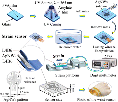
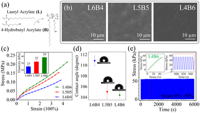
The preparation process of AgNWs@acrylate copolymer sensors is shown in Fig. 1 and described in the ESI† (material and methods). A transfer “printing” mask prepared the patterned AgNWs on acrylate flexible substrates. Methods of characterization and strain sensitivity of sensors were described in the ESI.† The chemical structures of two acrylate copolymers and their reaction are shown in Fig. 2(a). The SEM morphology of the flexible substrate L6B4, L5B5 and L4B6 films are shown in Fig. 2(b). The surface of the acrylate films had a cross-woven shape, which increased the contact area. Due to this form, there was increased interconnection between AgNWs and the substrate surface, which prevents the AgNWs from falling off easily during the stretching process.
The stress–strain curves and elastic modulus (inset) of the L6B4, L5B5, and L4B6 films are shown in Fig. 2(c). These acrylate films were stretched more than three times their length, and all have good linearity within 300% of the tensile strain. Compared with the conventional PDMS substrate, these three elastomer films were more flexible, with an elastic modulus of 25.2 kPa, 32.3 kPa, and 38.6 kPa, respectively (Fig. 2(c, inset)). Their elastic modulus is two orders of magnitude smaller than PDMS (which has an elastic modulus of about 1 MPa),27 and their mechanical flexibility is closer to human skin (Young's modulus of about 50 kPa).28 Meanwhile, these acrylate films are transparent and can be easily prepared in different shapes or sizes according to demand. Since flexible strain sensors should have good flexibility and stretchability and require a certain feedback force, the L4B6 film was more suitable as flexible sensor substrates. Fig. 2(d) shows the results of the three acrylate copolymer films' water contact angle tests. The contact angles of L6B4, L5B5 and L4B6 elastomer substrates were 110.86°, 105.33° and 104.43°, respectively, which indicates that changing the monomer ratio will cause the surface activation energy of acrylate copolymers to change. Those acrylate elastomers exhibit hydrophobic properties, similar to the water contact angle of PDMS (from 110–124° to ∼91°).29 A more hydrophobic surface means less roughness, which means better water resistance. These parameters of an elastomer film are crucial for the uniform coating of nanomaterials (in our case, AgNWs) and are directly related to the performance of the sensors. Fig. 2(e) shows the stretching/releasing cycling test near 50% strain and the tensile speed ∼0.1 mm s−1. The stress–strain hysteresis curve is shown for a representative L4B6 film. The results confirm high reproducibility for more than 1000 cycles.
Fig. S1† shows the investigation of the structure and functional groups of acrylate copolymer elastomers (ATR FTIR and Raman spectra). The influence of the different monomer ratios on side chains and functional groups was analyzed. The findings, as presented in Fig. S2,† are a supplement to the data in Fig. 2(c and d) and offer a systematic analysis of the mechanical properties associated with the sensor sensitivity (Fig. 3(a)).
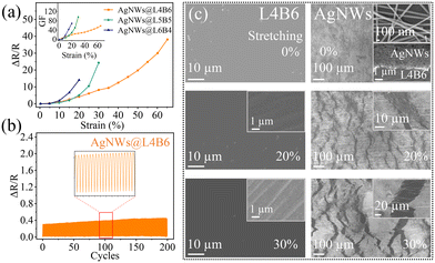
The tensile test was performed on AgNWs@L4B6, AgNWs@L5B5 and AgNWs@L6B4 strain sensors and the relationship curves between tensile strain and the rate of change of resistance ΔR/R0 are shown in Fig. 3(a). The value of the relative change of resistance increases and based on AgNWs@L4B6, the strain sensor sensing range can reach 50% or even greater. The other two AgNWs@L5B5 and AgNWs@L6B4 sensors showed sensitivity with increasing load in the range of up to 30% and 20%, respectively.
The sensitivity (GF) was expressed as the ratio between the relative change in resistance and the applied tensile strain:30
 | (1) |
Due to the cracks (breaks) in the conductive path shown in Fig. 3(c) and described in the ESI† (strain analysis of the L4B6 acrylate copolymer film and AgNWs, Fig. S3†),31 during the stretching process, the sensor's initial resistance value at each stage of the load and unload cycle does not match that value.32 So ΔR/R0 also drifted upward with the increase in the number of cycles. This increase in relative resistance is not significant in the short term, as shown in the insets for each sensor, but has an upward trend throughout the test.
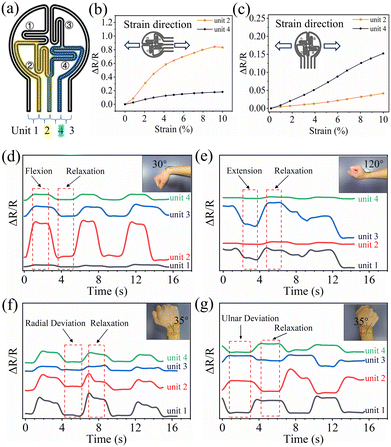
By designing the strain sensor as four grids with parallel and perpendicular placements relative to each other (Fig. 4(a)), the sensors are highly selective for the change of strain direction.33 According to the parameters of the stretching/releasing cycling test near 10% load and the tensile speed ∼0.1 mm s−1, the relative resistance ΔR/R0 of the representative AgNWs@L4B6 strain sensor was measured for different directions of the contact grid and strain directions. The measurement results show that the relative resistance change ΔR/R0 of the parallel grid element to the direction strain was higher than ΔR/R0 of the perpendicular grid element to the strain direction (Fig. 4(b) and (c)). For the sensor stretched along the direction parallel to the strain direction, the load led to a significant response ΔR/R0. On the other hand, the sensor showed a small response for strain in the perpendicular direction. This directional resistance variation originated from the fact that the resistance change was proportional to the length of the AgNW electrodes in the strain direction. The short length in the perpendicular direction means that the perpendicular strain had less impact on the total resistance of the sensor, whereas the parallel direction strain could cause large resistance to change quickly.33 The correlations between experimental data and simulation (Fig. S4) are further discussed in the ESI,† shedding light on the underlying mechanism. In this regard, Table S1† shows the relative values of the resistance of each section without stretching. A comparison of elongation at break and strength for the AgNWs@L4B6 strain sensor with different AgNW concentrations is shown in Fig. S5.†
To prove the feasibility of our development design, the AgNWs@L4B6 strain sensor was mounted for the human wrist to detect the uniaxial bending and multiaxial motions. First, the measurements were performed between pins 1 and 5 (Fig. S6†), which includes all the resistors (units 1–4 – Fig. 4(a)). The measurements demonstrated the sensitivity of the sensor to hand movement. However, the value of the change in resistance differed between the bending of the sensor (the hand moved up or down relative to the wrist) and the radial deviation (the hand moved left or right relative to the wrist). Second, the measurements were performed between everything in units 1–4 of the sensor. Fig. 4(d–g) shows these results, where unit 2 and unit 3 parallel to the direction of motion have higher resistance changes than unit 1 and unit 4 perpendicular to the direction of motion under the movements of wrist flexion and wrist extension, respectively. This way, the wrist's deviation and extension can be distinguished according to this change. Thus, the sensor is prominent in detecting wrist movements of flexion, extension, ulnar and radial degrees of freedom. It can be assumed that all 360° movements can be detected this way.
Conclusions
In this article, a flexible strain sensor with good flexibility and stretchability was prepared by using AgNWs and acrylate film. The flexible strain sensors based on AgNWs@L5B5 and AgNWs@L6B4 showed higher strain sensitivity factors GF = 97 and GF = 70, respectively. However, they have a limited stretch range of up to 25% and the lowest parameter of linearity R2, therefore wrist movement monitoring was shown for the AgNWs@L4B6 sensor with sensitivity GF = 58 at strain 68% and R2 ∼ 98. The four grids on the sensor are designed to detect wrist movements in various directions selectively. The sensor can also detect knee bending and finger tapping motion.Author contributions
Shuhao Li and Jian Yang: conceptualization, Wenjin Wu: methodology, Weiquan Chen: software, Shuhao Li and Yu Chang: validation, Yijie Liu and Zifeng He: formal analysis, Yan Pu and Wenjin Wu: investigation, Shuhao Li: writing – original draft preparation, Ivan S. Babichuk and Jian Yang: writing – review and editing, Shuhao Li visualization, Terry Tao Ye, Zhaoli Gao and Jian Yang: funding acquisition.Conflicts of interest
There are no conflicts to declare.Acknowledgements
This research was supported by the Key-Area Research and Development Program of Guangdong Province (2020B0101030002), and in part by Wuyi University-Hong Kong-Macao Joint Research Funds (2019WGALH19).Notes and references
- M. Ali, S. M. Hoseyni, R. Das, M. Awais, I. Basdogan and L. Beker, Adv. Mater. Technol., 2023, 8, 2300347 CrossRef CAS.
- L. Wang, F. Wei, Z. Zhai, R. Zhang, W. Liu and Z. Zhao, Sens. Actuators, A, 2024, 365, 114909 CrossRef CAS.
- C. Lin, W. Wu, H. Zhu, Y. Qiu, S. Cui, W. Chen, I. S. Babichuk, T. T. Ye, Z. Gao and J. Yang, Adv. Mater. Technol., 2023, 8, 2202142 CrossRef CAS.
- J. Chen, Y. Zhu, X. Chang, D. Pan, G. Song, Z. Guo and N. Naik, Adv. Funct. Mater., 2021, 31, 2104686 CrossRef CAS.
- J. Yang, Front. Bioeng. Biotechnol., 2022, 10, 849617 CrossRef PubMed.
- J. Gu, Y. Shen, S. Tian, Z. Xue and X. Meng, Biosensors, 2023, 13, 1025 CrossRef CAS PubMed.
- F. Basarir, Z. Madani and J. Vapaavuori, Adv. Mater. Interfaces, 2022, 9, 2200866 CrossRef CAS.
- Y. Heo, Y. Hwang, H. S. Jung, S. H. Choa and H. C. Ko, Small, 2017, 13, 1700070 CrossRef PubMed.
- H. Wang, M. Jian, S. Li, X. Liang, H. Lu, K. Xia, M. Zhu, Y. Wu and Y. Zhang, Adv. Mater., 2023, 35, 2306144 CrossRef CAS PubMed.
- Q. Liu, J. Chen, Y. Li and G. Shi, ACS Nano, 2016, 10, 7901–7906 CrossRef CAS PubMed.
- B. Chen, L. Zhang, H. Li, X. Lai and X. Zeng, J. Colloid Interface Sci., 2022, 617, 478–488 CrossRef CAS PubMed.
- A. K. Tareen, K. Khan, M. Iqbal, S. Golovynskyi, Y. Zhang, A. Mahmood, N. Mahmood, J. Long, A. Al-Ghamdi, C. Li and H. Zhang, Mater. Today Chem., 2022, 26, 101205 CrossRef CAS.
- K. K. Yeung, J. Li, T. Huang, I. I. Hosseini, R. Al Mahdi, M. M. Alam, H. Sun, S. Mahshid, J. Yang, T. T. Ye and Z. Gao, Nano Lett., 2022, 22, 6647–6654 CrossRef CAS PubMed.
- X. Yang, H. Yao, G. Zhao, G. A. Ameer, W. Sun, J. Yang and S. Mi, J. Mater. Sci., 2020, 55, 9551–9561 CrossRef CAS.
- T. Yang, D. Xie, Z. Li and H. Zhu, Mater. Sci. Eng., R, 2017, 115, 1–37 CrossRef.
- Z. Liu, D. Qi, P. Guo, Y. Liu, B. Zhu, H. Yang, Y. Liu, B. Li, C. Zhang, J. Yu, B. Liedberg and X. Chen, Adv. Mater., 2015, 27, 6230–6237 CrossRef CAS PubMed.
- J. Wang, H. Liu, X. Yue, D. Zhang, R. Yin, H. Sun, C. Liu and C. Shen, Mater. Today Nano, 2023, 24, 100427 CrossRef CAS.
- C. Wang, J. Zhao, C. Ma, J. Sun, L. Tian, X. Li, F. Li, X. Han, C. Liu, C. Shen, L. Dong, J. Yang and C. Pan, Nano Energy, 2017, 34, 578–585 CrossRef CAS.
- S. Chen, Y. Wei, S. Wei, Y. Lin and L. Liu, ACS Appl. Mater. Interfaces, 2016, 8, 25563–25570 CrossRef CAS PubMed.
- W. Chen, Y. Qiu, I. S. Babichuk, Y. Chang, R. Zhou, Z. He, Y. Liu, J. Zhang, I. V. Babichuk, A. Tiutiunnyk, D. Laroze, V. V. Brus and J. Yang, Adv. Eng. Mater., 2023, 26, 2301470 CrossRef.
- Z. He, Y. Liu, I. S. Babichuk, Z. Zhou, Z. Liu, X. Yang, R. Zhou, Y. Pu, S. Li, Y. Chang, T. T. Ye, Z. Gao and J. Yang, Adv. Mater. Technol., 2024, 2024, 2400386 CrossRef.
- S. Cichosz, A. Masek and M. Zaborski, Polym. Test., 2018, 67, 342–348 CrossRef CAS.
- J. Min, Y. Song and W. Gao, Nat. Electron., 2022, 5, 717–718 CrossRef.
- L. Fan, W. Zheng, J. Xu and G. Yin, Sens. Actuators, A, 2023, 364, 114823 CrossRef CAS.
- J. Huang, A. Chen, S. Han, Q. Wu, J. Zhu, J. Zhang, Y. Chen, J. Liu and L. Guan, Adv. Sci., 2023, 10, 2301116 CrossRef CAS PubMed.
- Y. J. Moon and K.-T. Kang, Flexible Printed Electron., 2022, 7, 024003 CrossRef CAS.
- R. Seghir and S. Arscott, Sens. Actuators, A, 2015, 230, 33–39 CrossRef CAS.
- A. Kalra, A. Lowe and A. M. Al-Jumaily, J. Mater. Sci. Eng., 2016, 5, 1000254 Search PubMed.
- M. Kanungo, S. Mettu, K.-Y. Law and S. Daniel, Langmuir, 2014, 30, 7358–7368 CrossRef CAS PubMed.
- X. Wang, H. Li, T. Wang, X. Niu, Y. Wang, S. Xu, Y. Jiang, L. Chen and H. Liu, RSC Adv., 2022, 12, 14190–14196 RSC.
- I. S. Babichuk, C. Lin, Y. Qiu, H. Zhu, T. T. Ye, Z. Gao and J. Yang, RSC Adv., 2022, 12, 27687–27697 RSC.
- Y. Bu, T. Shen, W. Yang, S. Yang, Y. Zhao, H. Liu, Y. Zheng, C. Liu and C. Shen, Sci. Bull., 2021, 66, 1849–1857 CrossRef CAS PubMed.
- H.-C. Lu and Y.-C. Liao, Nanomaterials, 2021, 11, 2583 CrossRef CAS PubMed.
Footnote |
| † Electronic supplementary information (ESI) available: Morphology, structure and strain investigations of acrylate substrates; wrist movement monitoring. See DOI: https://doi.org/10.1039/d4lf00081a |
| This journal is © The Royal Society of Chemistry 2024 |


