 Open Access Article
Creative Commons Attribution 3.0 Unported Licence
Synthesis of diverse stable MOFs and their electro catalytic capabilities towards desulfurization, water splitting and various nitrophenol reduction reactions†
Manivannan
Mahendran
ac,
Yazhmozhi
Mariappan
a,
Rahul
Thamizhselvan
*bc and
Suryanarayanan
Vembu
 *ac
*ac
aElectro Organic & Materials Electrochemistry Division, CSIR-Central Electrochemical Research Institute, Karaikudi-630003, Tamil Nadu, India. E-mail: vidhyasur@yahoo.co.in; surya@cecri.res.in
bElectrochemical Power Sources Division, CSIR-Central Electrochemical Research Institute, Karaikudi-630003, Tamil Nadu, India
cAcademy of Scientific and Innovative Research (AcSIR), Ghaziabad-201002, India
First published on 15th March 2024
Abstract
Metal–organic frameworks are a novel class of crystalline porous materials with enormous application potential, consisting of metal nodes and organic linkers. Because of their adjustable porosity, significant surface area and adaptability to various ligands and metal centers for functionalization, MOFs are considered to be highly promising electrocatalytic materials in different fields. This work explains the simple synthesis of carbonized MOFs (Al, Ni and Co–C MOFs) by a hydrothermal method, and their characterization for functional moieties and morphological structures by different surface analytical methods, followed by exploring them as model catalysts for water splitting, electrooxidation of thiophene (TP), benzothiophene (BT) and dibenzothiophene (DBT) and reduction of p-nitrophenol (p-NP), 2,4-dinitrophenol (DNP) and 2,4,6-trinitrophenol (TNP). Co–C MOF shows the lowest onset potential of 1.54, 1.52 and 1.55 V with a lower Tafel slope value of 69, 126 and 126 mV dec−1 with a charge transfer resistance value (Rct) of 4238, 4864 and 6327 Ω for the electrooxidation of TP, BT and DBT, respectively. Interestingly, the synthesized Ni–C MOF exhibits the best hydrogen evolution reaction (HER) activity when compared to Al and Co–C MOFs, bearing the lowest value of overpotential (225 mV), Tafel slope (114 mV dec−1) and charge transfer resistance (130 Ω). Furthermore, the synthesized Co–C MOF also provides the best oxygen evolution reaction (OER) activity and displays the lowermost overpotential, Tafel slope and charge transfer resistance values of 220 mV, 169 mV dec−1 and 149 Ω, respectively. In addition, all three nitro compounds were totally reduced by synthesized Ni–C MOF, providing excellent performance with minimum reduction time. The outstanding activity of the synthesized Co and Ni–C MOFs towards desulfurisation and OER activity as well as the HER and nitrophenol reduction, respectively, is associated with high electrochemical active surface area (ECSA) and enlarged pore volume leading to innumerable active sites, resulting in enhanced performance.
1. Introduction
Metal organic frameworks (MOFs) are innovative organic–inorganic hybrid materials with numerous potential applications in molecular recognition, gas storage, catalysis, sensing, optics, gas separation, batteries, etc.1,2 MOFs are a family of porous coordination polymers, consisting of coordination bonds formed by metal centers and organic ligands. Due to its vast surface area, tunable porosity and ability to adapt to various metal centers and ligands, MOFs are regarded as promising electrocatalytic materials.3,4 The distance that charge carriers must travel to reach the reactants can be greatly reduced when using MOFs with high porosity and accessible surface area in electrocatalysis. To increase both chemical and thermal stability, an organic ligand must covalently bind with different metal ions. These benefits have sparked intense interest in MOFs, which have also been investigated as potential electrocatalytic materials.5,6 To improve the catalytic activity of MOFs further, a few strategies are adopted, which include (i) enhancing the accessibility of the electrochemical catalytic active sites to modify the structure of the MOF materials, (ii) increasing the surface area of a substrate by lowering the size of the particles or growing MOFs in situ on surfaces with a large surface area and (iii) implementing multivariate or bimetallic MOFs. Despite these benefits, they are not frequently used in electrochemical processes due to their low electrical conductivity, insulating qualities and poor chemical stability in aqueous solution at ambient temperature.2,7 To overcome this and to achieve the optimal performance, conductive materials are commonly composited in the MOF derivatives/compositions.4,5,8 Another strategy is to carbonize the pristine MOFs at a temperature of 500 °C under an inert atmosphere in order to generate MOF-based carbon composites to produce heteroatom-doped porous carbons decorated with metal/metal oxide nanoparticles. In this aspect, it is expected that the carbonized MOFs perform better than the pristine MOF materials.9–12Regulations to lower the sulfur content of hydrocarbon fuels are essential because when they burn, sulfur compounds can be released into the atmosphere, damaging the environment and posing a health risk to humans.13,14 One of the most prevalent contaminants found in crude oil is sulfur-containing compounds. The sulfur content of liquid fuel oil directly contributes to the emission of SO2 and sulfate particulates, endangering public health and communal property.13 It also shortens the engine's life owing to corrosion. Traditional methods of removing sulfides, like catalytic combustion, thermal incineration, activated carbon adsorption and organic solvent absorption, involve costly secondary treatment, time-consuming procedures and risks of fire, explosion and secondary pollution.14–16 It is very easy and inexpensive to conduct electrochemical desulfurization (ECDS) by oxidizing sulfur compounds.17,18 The electrochemical anodic oxidation of sulfides is shown in eqn (R1).
| R-SH + 4OH− + 4e− → RH + SO2 + 2H2O | (R1) |
It has been extensively investigated how thiophene, one of the components in fossil fuels, can be electrochemically oxidized at platinum, lead/lead oxide, a dimensionally stable anode (DSA) electrode and a boron-doped diamond (BDD) electrode.19,20 A novel benzothiophene catalyst, namely 2-(4-(2-pentylbenzothiophen-3-yl)benzylidene)malononitrile, was reported by Ozak et al. showing excellent activity, good stability and potential as an anode for glucose fuel cells.21 Dibenzothiophene and its derivatives were either individually or collectively electrochemically oxidized on a BDD anode in an acetonitrile–water solution. Depending on the used anodic potential, the primary compounds found were the matching sulfoxides or sulfones, in which the potential oxidative pathways of the dibenzothiophene compounds are suggested.22 Although there isn't much research on the ECDS process using these anodes in the literature, the decomposition voltages in both organic and aqueous electrolytes are relatively high. Some metals or metal oxides cannot be widely commercialized because of their high cost and finite supply. Instead of using expensive materials and risking metal poisoning, MOFs are thought of as excellent catalysts for sulfide electrooxidation.23,24 In our previous work, binary and ternary MOFs containing Ni, Co and Al metal nodes were explored as excellent catalysts for efficient electrooxidation of thiophene.1
In recent years, the need for clean and sustainable energy solutions has increased in response to the deterioration of the environment. One of the promising techniques for producing hydrogen fuel from water in an environmentally friendly manner is electrochemical water splitting. The chemistry needed to actualize a hydrogen economy is efficient hydrogen production from water splitting. Recently Chen et al. reported pressure-induced bimetallic nitrogen/sulfur double-doped carbon nanotubes from MOFs as electrocatalysts for water splitting reactions.25 Water electrolyzers can produce hydrogen through an oxygen evolution reaction (OER) at the anode and a hydrogen evolution reaction (HER) at the cathode.26 Hydrogen adsorption occurs at the electrode surface during the HER, and as the adsorption energy varies depending on the kind of electrode material used, the HER kinetics are also influenced by the material type. There are two types of hydrogen adsorbed on surfaces. Underpotentially deposited hydrogen (UPD) is a strong hydrogen adsorption that occurs at several noble metals (Pt, Rh, Ru, Ir and Pd). Another type of adsorbed hydrogen is hydrogen that has been over-potentially deposited. Kai et al. created an improved electrocatalyst for the OER using a meso–macro hierarchical porous Ni3S4 architecture that is enriched in Ni3+ and exhibits high activity and stability.27 The OER is crucial to the conversion and storage of energy, especially in the electrolysis of water. Xue et al. reported Co and Fe MOF derived species on N-doped carbon networks as efficient oxygen electrocatalysts for Zn–Air batteries.28 K. Wan et al. reported a practical method for creating metal–carbon nanohybrid mesoporous nickel sulfides/nitrogen-doped mesoporous carbon electrocatalysts for inexpensive energy conversion and storage devices.29 Currently, precious metals and their oxide compounds (Ru, Ir, RuO2 and IrO2) are broadly used in the OER process as catalysts to minimize energy consumption and improve energy conversion efficiency.30–32 Kai et al. reported a sulfur-modified nickel selenide electrocatalyst that exhibits good stability at 50 mA cm−2 with a 7.5% increase of overpotential after 100 hours and another report by the same group involves the use of a simple cation regulation technique to pyrolyze the Ni–Co bimetallic MOF, leading to an increase of the OER activity of metal sulfides.33,34 Qi et al. used a nickel-terephthalic acid-based MOF (Ni MOF) and N2/H2 plasma activation strategy and developed a technique to implant multiple HER active species (Ni, Ni3N and MoNi4) in molybdenum-based polyoxometalate (POM)-encapsulated Ni MOF nanosheet arrays.35 A facile one-pot approach is reported by Chang et al. to synthesize RuO2-incorporated NiFe-MOFs (RuO2/NiFe-MOF) with unique nanobrick-nanosheet heterostructures as a precatalyst.36 However, large-scale manufacture of these catalysts is not possible due to their limited availability, high cost and short durability. To reduce their overpotentials and encourage the practical use of energy related devices, efficient electrocatalysts for these HER and OER processes are widely required. MOFs have recently emerged as electrocatalysts with high electrical conductivity and uniformly dispersed active sites. MOFs are types of materials with an open crystalline structure, remarkable porosity, structural flexibility and programmable functionality that are made by joining metal ions or clusters with organic linkers.37
Since nitrophenol derivatives such as p-nitrophenol (p-NP), 2,4-dinitrophenol (DNP) and 2,4,6-trinitrophenol (TNP) are regarded as poisonous compounds, produced by industrial waste and farming, finding a proper method of disposal is crucial.38 When p-NP, DNP and TNP are reduced by a metal catalyst in the presence of NaBH4, 4-aminophenol is produced. Paracetamol is a crucial intermediate, used in this synthesis and it is also used in the dye industry. Therefore, from an industrial perspective, it is crucial to develop innovative processes for reducing nitrophenol to the corresponding aminophenol.1
Herein, we report a one-pot synthesis of monometallic carbonized metal organic framework (C-MOF) using benzene tricarboxylic acid as linkers and Co, Ni and Al as metal precursors. The C-MOFs were characterized for functional groups, elemental analysis and surface morphology using a variety of analytical techniques and explored as catalysts for electrochemical water splitting and reduction of p-NP, DNP and TNP. Furthermore, for the first time, the synthesized C-MOFs were employed as catalysts for the electrooxidation of thiophene (TP), benzothiophene (BT) and dibenzothiophene (DBT), taken as model compounds, by coating the materials on a glassy carbon electrode (GCE) to study their electrochemical performance towards ECDS.
2. Experimental methods
2.1 Reagents
Cobalt, aluminium and nickel nitrate hexahydrate were purchased from Merck and used as a metal precursor. TCI chemicals provided the 1,3,5-benzene tricarboxylic acid. SRL chemicals supplied the N,N-dimethyl formamide (DMF). TP, BT, DBT, 4,4-bipyridine and triethyl amine were purchased from Sigma Aldrich. p-NP, DNP and TNP were obtained from TCI chemicals.2.2 Physical characterizations
The spectrum range of 400–2000 cm−1 was measured using a Fourier transform infrared spectrometer (FTIR) to define the functional groups of C MOFs (TENSOR 27, Bruker Optik GmbH, Germany). To examine the material's phase and crystal structures, an X-ray diffractometer was used (XRD, Bruker, Germany). The surface morphological images of the synthesized MOFs, element mapping and energy dispersive X-ray spectroscopy (EDAX) spectrum were depicted using FESEM (field emission scanning electron microscope) analysis (Supra 55VP, Carl Zeiss, Germany). X-Ray photoelectron spectroscopy [ESCALAB xi, Thermo scientific model] (XPS) was used to record the chemical composition of the active compounds. From TEM analysis (FEI TECNAI 20 G2) elemental mapping, morphological and lattice fringe analyses were performed. The surface area of the MOF materials was calculated using BET measurement (Quantachrome instruments 5.0, Autosorb iQ, chemisorption analyzer and advanced micropore size). Electrochemical studies such as chronoamperometry (CA), OER, HER and linear sweep voltammetry (LSV) were performed using a BioLogic electrochemical work station SP-150.2.3 Synthesis of monometallic carbonized MOFs
In a beaker containing DMF solvent (80 ml), 1,3,5-benzene tricarboxylic acid, 4,4′-bipyridine as a linker and aluminium nitrate hexahydrate were kept to synthesize a Al–C MOF. The mixture was then poured and transferred into an autoclave for 12 h at 120 °C and allowed to cool until it reaches room temperature. Using ethanol, the resultant product of Al-MOF was washed and filtered. Finally, the filtered Al-MOF product was dried at 60 °C for 12 h. Additionally, carbonization was performed at 500 °C in an inert atmosphere. The same procedure was used to synthesize the Co–C MOF and Ni–C MOF using cobalt nitrate hexahydrate and nickel nitrate hexahydrate as a metal precursor, respectively.2.4 Fabrication of electrode materials
Before electrochemical investigations, the GCE was polished with a 0.05 mM alumina suspension to remove any surface defects, then washed with double distilled water and left to air dry. First, 5 ml of ethanol was used to emulsify 10 mg of the modified MOF. The ultrasonic treatment produced a uniform black slurry after two hours. The solvent was eliminated by exposing the ethanol-based modifier to fresh air following its drop casting over the polished GCE surface. Additionally, DD water was used to clean the modified electrode prior to its use in electrochemical tests.2.5 Electrooxidation
The electrochemical studies of carbonized MOFs were investigated using LSV and EIS with a GCE (3 mm diameter), Hg/HgO and Pt wire serving as the working, reference and counter electrodes, respectively. LSV was performed at a scan rate of 50 mV s−1 in 0.5 M H2SO4 for both TP and BTP and 10% acetonitrile for DBT. The EIS was recorded in the range of 10 HZ to 100 mHZ. Charge transfer resistance (Rct) was obtained by EIS and Tafel slope values were obtained by LSV. The HER and OER investigations were conducted at a scan rate of 50 mV s−1 in 0.5 M H2SO4 and 1 M KOH solutions using a GCE (3 mm diameter), a calomel electrode and a graphite rod as the working, reference and counter electrodes, respectively.3. Results and discussion
3.1 Characterisation studies
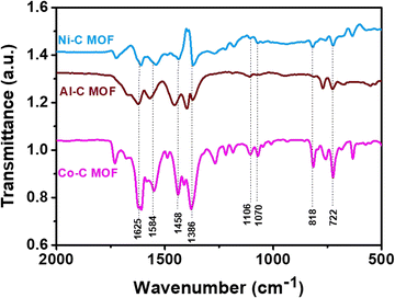
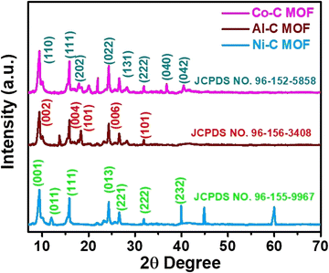
The recorded FT-IR spectra for the Co, Ni and Al–C MOF samples are shown in Fig. 1 in the spectral region of 400–2000 cm−1. The peaks detected at 1625 and 1584 cm−1 correspond to the stretching and anti-symmetric stretching vibrations of carboxylate groups, respectively. At 1386 cm−1, the C–O and O–H stretching are seen in a wide band. The peaks that emerged at 1106 and 1070 cm−1 represent the C–N and C–O stretching, respectively. The aromatic group out of plane vibrations and the M–O (M = Al, Co and Ni) peaks are found at 722 and 818 cm−1, respectively.The powder X-ray diffractometer (PXRD) pattern reveals that the synthesized Co, Al and Ni–C MOFs exhibit more crystallinity with sharp and strongly intense peaks. The Al–C MOF peaks are observed at 2θ values of 9.47°, 15.99°, 18.34°, 24.22° and 31.84°, which correspond to the planes (002), (004), (101), (006) and (101), respectively.39 Similarly, the Co–C MOF peaks are seen at 2θ values of 9.39°, 15.82°, 17.95°, 24.30°, 28.30°, 31.84°, 36.78° and 40.39°, related to the planes (110), (111), (202), (022), (131), (222), (040) and (042), respectively.40,41 Furthermore, the peaks of Ni–C MOF are noted at 9.39° (001), 11.98° (011), 15.82° (111), 24.30° (013), 26.58° (221), 31.91° (222) and 39.92° (232).42–44 The resultant XRD pattern does not show extra peaks, indicating the purity of the synthesised Co, Al and Ni–C MOFs (Fig. 2).
Field emission scanning electron microscopy (FE-SEM) was used to depict the surface morphological images of the synthesized Co, Al and Ni–C MOFs. Fig. 3 shows the crystalline square shape surface morphological images of the synthesized Co, Al and Ni–C MOFs, which indicates the more stable compact structure, leading to a large number of agglomerated particles with a size range of 200 nm and a shape that is virtually spherical over the crystal. The EDAX analysis also validates the existence of metal ions (Al, Co and Ni) in the synthesised Co, Al and Ni–C MOFs. Additionally, the elemental weight % of the metal ions in the C-MOFs is displayed in Table S1 and Fig. S1 (ESI†).
The physical properties of the carbonized MOFs were investigated using the Brunauer–Emmett–Teller (BET) and Barrett–Joyner–Halenda (BJH) techniques. The surface area was examined through N2 adsorption–desorption isotherms, as illustrated in Fig. 4 for the Al–C MOF (a and d), Co–C MOF (b and e) and Ni–C MOF (c and f). The mesoporous nature of the MOFs was indicated by the distinctive type IV isotherms with hysteresis loops that each catalyst displayed in the relative pressure range of 0.4–0.8. Additionally, at low P/Po, the N2 adsorption–desorption isotherms of Co, Ni and Al–C MOFs show a vertical rise, indicating the presence of numerous micropores. Surface area and pore volume data for the synthesized MOFs are displayed in Table S2 (ESI†). Co–C MOF demonstrates the highest surface area of 164![[thin space (1/6-em)]](https://www.rsc.org/images/entities/char_2009.gif) m2 g−1, followed by Ni–C MOF (147 m2 g−1) and Al–C MOF (123 m2 g−1) respectively. In a similar manner, Co–C MOF provides higher pore volume than that of Ni and Al C MOF (Table S2, ESI†).
m2 g−1, followed by Ni–C MOF (147 m2 g−1) and Al–C MOF (123 m2 g−1) respectively. In a similar manner, Co–C MOF provides higher pore volume than that of Ni and Al C MOF (Table S2, ESI†).
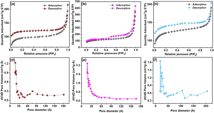 | ||
| Fig. 4 BET pore size distribution plot of (a and d) Al–C MOF, (b and e) Co–C MOF and (c and f) Ni–C MOF. | ||
Fig. 5 exhibits the HR-TEM images of the synthesised Co–C MOF, revealing particle sizes ranging from 200 to 500 nm with a wrinkled petal-like structure. In addition, energy-dispersive X-ray spectroscopy and HR-TEM were used to map the elemental distribution of the synthesised carbonized MOFs. The diffraction dots of the plane (020) and (040) from the SAED pattern are shown in Fig. 5c and the interplanar distance (dspacing) of 0.520 and 0.60 nm obtained from PXRD is displayed in Fig. 2. The elemental mapping of the selected area displays the distribution of HAADF, in addition to C, N, O and Co. It is evident that the distribution of C (yellow), N (blue), O (red) and Co (purple) on the framework is consistent, demonstrating the homogeneous dispersion of the synthesised Co–C MOF (Fig. 5e–h). In a similar manner, the HR-TEM images of Al and Ni–C MOFs are displayed in Fig. S2 (ESI†).
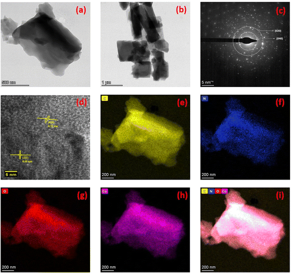 | ||
| Fig. 5 (a) and (b) HR-TEM images of Co–C MOF, (c) SAED pattern, (d) lattice fringes of Co–C MOF, (e–h) mapping results of C, N, O and Co, respectively; (i) mixed colour mapping results of Co–C MOF. | ||
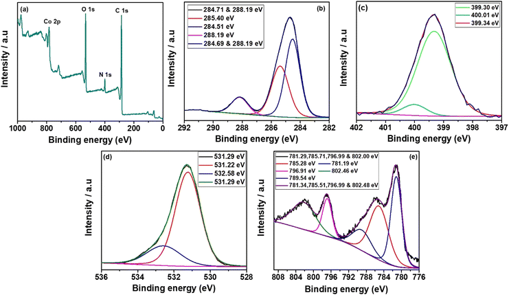
The synthesized Co, Al and Ni–C MOFs were subjected to XPS investigations to clarify the composition of elements present in synthesised C MOFs. Fig. 6(a–e) shows the XPS spectra of Co–C MOF. The entire Co–C MOF XPS survey spectrum is displayed in Fig. 6a and it indicates the existence of C 1s, N 1s, O 1s and Ni 2p. Fig. 6b displays the deconvoluted fitted curves with peaks, corresponding to C–C (284.69 eV), C–N (284.41 eV) and C–O (285.70 eV). Fig. 6c exhibits the detections of the graphite N, pyrrolidinic N and pyridinic N peaks that occurred at 400.01 eV, 300.34 eV and 399.30 eV, respectively.45,46 The Co–C MOF deconvoluted O1s spectrum is displayed in Fig. 6d. The O 1s spectrum provides peaks at 532.90 and 534.07 eV, which correspond to the C–O and C–O–H bonds, respectively. Furthermore, Co 2p peaks are detected at 780.14 eV (Co3+), 785.15 eV (Co2+), 788.41 eV, 795.88 eV (Co) and 802.06 eV.47 The XPS survey spectra of Al and Ni–C MOF, shown in Fig. S3 and S4 (ESI†), with their descriptions, once again confirm the presence of the respective metals and organic moieties in the MOF structure.
3.2 Electrochemical studies
For the electrocatalytic activities, the synthesized Al, Co and Ni carbonized MOF materials coated on the GCE electrode were investigated.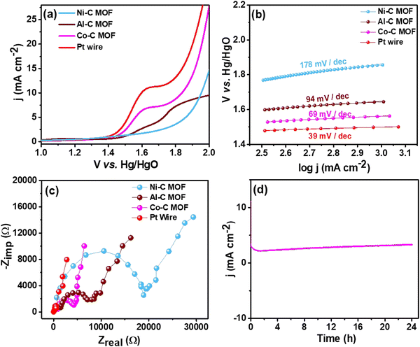 | ||
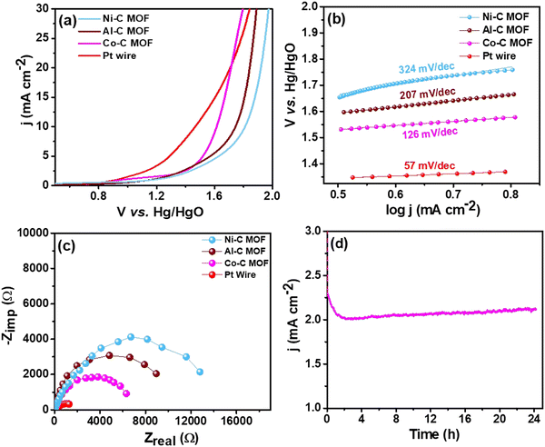
| Fig. 7 (a) LSV curves of the Pt wire electrocatalyst, Al, Co and Ni–C MOF in 0.5 M H2SO4 with 2 mM TP at a scan rate of 50 mV s−1, (b) & (c) Tafel slope & EIS spectra and (d) CA stability study. | ||
For better understanding of the oxidative kinetics, we measured the rate of electron transport at the electrode–electrolyte interfaces using the Tafel slope analysis by fitting the polarisation curve (overpotential η10vs. logaritham of the resultant current density) of the synthesized C MOF-modified GCE (Fig. 7b). Interestingly, the Al–C and Ni–C MOF provides higher values of 94 mV dec−1 and 178 mV dec−1, respectively, while the Co–C MOF shows the lowest Tafel slope of just 69 mV dec−1. Table S3 (ESI†) summarizes these materials and their electrocatalytic characteristics. The Pt wire has the lowest Tafel slope value of 39 mV dec−1 and lowest onset potential of 1.49 V when compared to the C MOF modified GCE.
Furthermore, EIS was used to analyze the Rct values, which are displayed in Fig. 7c. The Rct values of Al and Ni–C MOF are notably 18![[thin space (1/6-em)]](https://www.rsc.org/images/entities/char_2009.gif) 927 Ω and 8519 Ω, respectively, while the Co–C MOF has the lowest Rct value of 4238 Ω. These results show that the Co–C MOF has higher activity and more effective electron transport than the others. The benchmark catalyst Pt wire obviously exhibits the lowest Rct value of 547 Ω (Table S3, ESI†). The long-term stability of the ideal catalyst Co–C MOF was investigated for 24 hours using CA at the current density of 50 mA cm−2 (Fig. 7d).
927 Ω and 8519 Ω, respectively, while the Co–C MOF has the lowest Rct value of 4238 Ω. These results show that the Co–C MOF has higher activity and more effective electron transport than the others. The benchmark catalyst Pt wire obviously exhibits the lowest Rct value of 547 Ω (Table S3, ESI†). The long-term stability of the ideal catalyst Co–C MOF was investigated for 24 hours using CA at the current density of 50 mA cm−2 (Fig. 7d).
![[thin space (1/6-em)]](https://www.rsc.org/images/entities/char_2009.gif) 35 Ω, 14
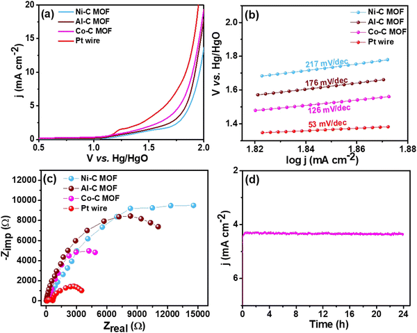
35 Ω, 14![[thin space (1/6-em)]](https://www.rsc.org/images/entities/char_2009.gif) 619 Ω and 4864 Ω, respectively (Fig. 8c). These values indicate that Co–C MOF has high activity and effective electron transport, when compared to Ni and Al–C MOFs. The benchmark catalyst Pt wire exhibits the lowest values of onset potential, Tafel slope and charge transfer resistance of 1.36 V, 53 mV dec−1 and 650 Ω, respectively. The detailed electrocatalytic characteristics are shown in Table S3 (ESI†). By using the CA technique, the long-term stability was investigated for the best catalyst Co–C MOF over 24 hours at the constant current density of 50 mA cm−2 (Fig. 8d).
619 Ω and 4864 Ω, respectively (Fig. 8c). These values indicate that Co–C MOF has high activity and effective electron transport, when compared to Ni and Al–C MOFs. The benchmark catalyst Pt wire exhibits the lowest values of onset potential, Tafel slope and charge transfer resistance of 1.36 V, 53 mV dec−1 and 650 Ω, respectively. The detailed electrocatalytic characteristics are shown in Table S3 (ESI†). By using the CA technique, the long-term stability was investigated for the best catalyst Co–C MOF over 24 hours at the constant current density of 50 mA cm−2 (Fig. 8d).
![[thin space (1/6-em)]](https://www.rsc.org/images/entities/char_2009.gif) 787 Ω and 6327 Ω, respectively (Fig. 9c, Table S3, ESI†). For Pt wire, the values of onset potential, Tafel slope and Rct values are 1.35 V, 83 mV dec−1 and 1287 Ω, respectively. Fig. 9d displays the long-term stability of Co–C MOF over 24 hours at a constant current density of 50 mA cm−2, using the CA method.
787 Ω and 6327 Ω, respectively (Fig. 9c, Table S3, ESI†). For Pt wire, the values of onset potential, Tafel slope and Rct values are 1.35 V, 83 mV dec−1 and 1287 Ω, respectively. Fig. 9d displays the long-term stability of Co–C MOF over 24 hours at a constant current density of 50 mA cm−2, using the CA method.
The electrochemical mechanistic pathway on the oxidation of sulfides has already been investigated in the previous literature. This includes the electrooxidation of sulfides to sulfoxide and sulfone and this follows extraction by a suitable solvent.48
3.3 Studies on water splitting
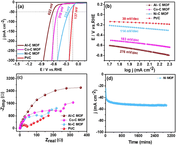
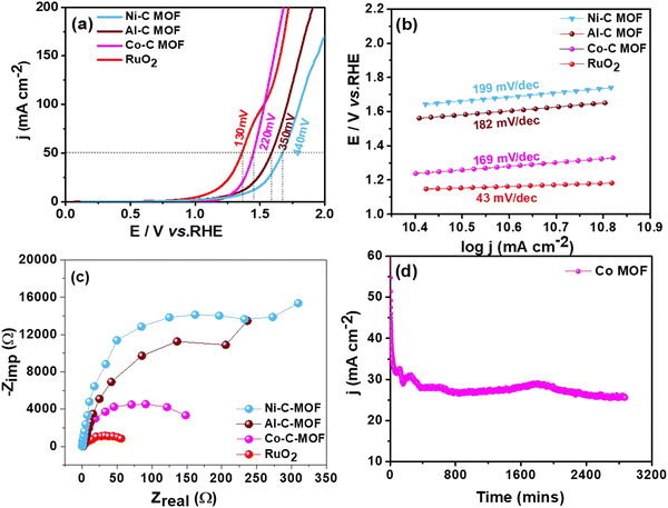
This section assesses the electrocatalytic activity of the synthetic C-MOF materials coated on a GCE towards HER and OER processes.3.4 Reduction of p-NP, DNP and TNP using Ni–C MOF
Among the typical processes for assessing the catalytic activity of noble metallic nanoparticles is the catalytic reduction of p-NP by borohydride ions, such as NaBH4 in the presence of a metal catalyst. The reaction is thermodynamically feasible but in the absence of a catalyst, its kinetics are restricted due to the very high kinetic barrier between the negatively charged ions p-NP and BH4−. The catalytic reduction of p-NP by metallic nanoparticles states that reactant molecules sticking to the metallic nanoparticle surface causes electron transfer from BH4− to p-NP. Amino compounds are widely used in the dye and pharmaceutical industries and exhibit less environmental risk than nitro compounds. Nitro compounds are extremely difficult to convert into their amine counterparts without the help of a catalyst because of the huge energy difference between their hydrogen 1s and nitrogen 2p orbitals. With a UV-Visible spectrophotometer, the catalytic activity of the synthesized Al, Co and Ni–C MOF in the reduction of p-NP was observed. The synthesized Ni–C MOF exhibits better performance compared to Al–C MOF and Co–C MOFs. At 400 nm, p-NP usually absorbs in the UV-vis absorption spectrum. The solution turned dark yellow instead of light yellow due to the formation of an intermediate 4-nitrophenolate ion and a new peak for Ni–C MOF for the p-aminophenol (p-AP) synthesis developed at 400 nm. The colour of the solution began to fade once the catalyst accumulated and this process took more time. The reduction of 4-NP to 4-AP by the synthesized Ni–C MOF took 10 min, indicating the improved catalytic activity of the compound. The rate constant values for the synthesized Ni–C MOFs with first-order kinetics are 20.60 × 10⁻² min−1, as noted from the kinetic graphs shown in Fig. 12a. A blank reaction without catalyst was also carried out in the presence of NaBH4 in order to have a better understanding of the catalyst function in these reduction reactions. Even after two hours in this reaction, there was no appreciable decrease in the intensity of absorbance, confirming that NaBH4 was unable to overcome the kinetic barrier.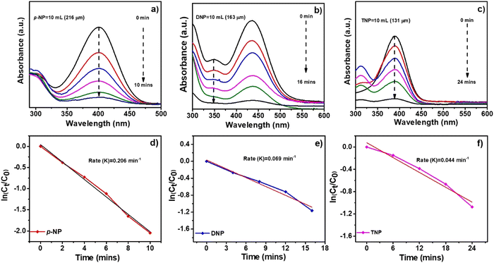 | ||
| Fig. 12 UV absorption spectra and kinetic plots for the reduction of (a and d) p-nitrophenol (p-NP), (b and e) dinitrophenol (DNP) and (c and f) trinitrophenol (TNP) by using Ni–C MOF. | ||
The reduction of other hazardous nitro compounds such as DNP and TNP was also examined to further broaden the application of Ni–C MOF reduction catalysis (Fig. 12b and c). In the UV-visible spectrum, the DNP and TNP typically absorb at 389 and 392 nm. The colour changes from light yellow to dark yellow and peaks appear at 349 and 390 nm, confirming the formation of 2,4-diaminophenol and 2,4,6-triaminophenol. The reduction of DNP to DAP and TNP to TAP by the synthesized Ni–C MOF took 16 and 24 min respectively. The rate constant values for DNP and TNP with first-order kinetics are 6.90 × 10⁻² and 4.40 × 10⁻² min−1 (Fig. 12). This above study once again confirms that Ni–C MOF shows superior catalytic activity. The reduction of p-NP, DNP and TNP using Al and Co–C MOFs is shown in Fig. 12. A description of the detailed comparison of the catalytic activity and the reduction times of p-NP, DNP and TNP using Al, Ni and Co–C MOFs are given in the ESI† (Fig. S6 and S7, Table S5).
In order to measure the active sites and comparable performance of the different carbonised materials, the electrochemical active surface area (ECSA) of all of the catalysts was investigated by the double layer capacitance (Cdl) method50 in the potential region of 0.1–0.2 V vs. Ag/AgCl with the increase of the scan rate; the corresponding plots are shown in Fig. S8 (ESI†). The ECSA values are calculated from the following equation:
| ECSA = j × Cs/Cdl | (1) |
From the above analysis, it is clearly understandable that the Co and Ni–C MOFs show greater activity and provide enhanced performance towards desulfurisation and OER activity as well as the HER and nitrophenol reduction, respectively, as evidenced from their higher ECSA values than that of Al–C-MOF. As we mentioned earlier, carbonisation of the MOFs leads to enhanced porosity, and large surface area and pore volume, which can improve the exposure of active sites and electron/mass transfer. Furthermore, the carbonization leads to high conductivity as a result of formation of oxide nanomaterials and improved stability, where the nanostructure can be synthesised in a variety of morphologies allowing effective electron transfer. Moreover, the organic linkers may help as the origin of N-doping, thus enabling the maximization of the conductivity of the carbon matrix. The higher activity of Co–C MOF towards the OER as well as on the electrochemical oxidation of sulfides is due to the fact that Co metal has an appropriate binding energy towards oxygen and sulfur atoms, when compared to Ni and Al.4 On the other hand, from the literature studies, it is understandable that as a single metal catalyst, Co is less active for the HER, when compared to Ni. The results prove that pure Ni-MOF has enormous catalytic active edge sites and follows the Volmer–Heyrovsky mechanism, leading to desorption of hydrogen as the rate determining step, favouring high activity towards the HER and chemical reduction of nitrophenol.5
In order to confirm the structure of Co–C MOF and Ni–C MOF even after carrying out long term polarisation for the OER and HER, the best carbonised MOF materials namely Co–C MOF and Ni–Co MOF were characterised by FE-SEM and XRD after performing a stability test in 1 M KOH for 48 hours. The FE-SEM images and XRD patterns of Co and Ni–C MOFs obtained after the long-term stability test are shown Fig. S9 and S10 (ESI†). The investigations clearly show that the materials are highly stable.
4. Conclusions
In summary, we used a hydrothermal method to synthesize carbonized MOFs using BTC and 4,4-bipyridine as linkers and Co, Ni and Al as metal sources, characterised their surface morphology, functional groups and elemental analysis using various analytical tools. The synthesized C MOFs catalysts were tested towards the electrooxidation of TP, BT and DBT as well as for HER and OER activity, followed by the chemical reduction of three different nitrophenols. The Co–C MOF has a higher surface area and pore volume size than the Ni and Al–C MOFs, as confirmed by their physical characteristics, where the results clearly confirm that the synthesized Co–C MOF exhibits the lowest onset potential of 1.54, 1.52 and 1.55 V with a lower Tafel slope value of 69, 126 and 126 mV dec−1 and a charge transfer resistance value (Rct) of 4238, 4864 and 6327 Ω for the electrooxidation of TP, BT and DBT, respectively. Furthermore, the synthesized C MOFs were tested for HER and OER activity under basic conditions. Interestingly, the Ni–C MOF shows the best catalytic performance towards the HER, exhibiting the lowest value of overpotential (217 mV), Tafel slope (114 mV dec−1) and charge transfer resistance (130 Ω). On the other hand, the synthesized Co–C MOF exhibits the best OER activity and shows the lowermost overpotential, Tafel slope and charge transfer resistance value of 270 mV, 169 mV dec−1 and 149 Ω, respectively. Moreover, the synthesised Ni–C MOF completely reduced all three nitro compounds, namely p-NP, DNP and TNP, demonstrating exceptional reduction activity.Data availability
CSIR-CECRI manuscript communication number: CECRI/PESVC/Pubs/2024-002.Author contributions
Manivannan Mahendran: experimentation, data curation and methodology. Yazhmozhi Mariappan: investigation. Rahul Thamizhselvan: visualisation and investigation. Suryanarayanan Vembu: conceptualization, writing & editing – original draft, investigation at all stage, funding acquisition and project administration.Conflicts of interest
The authors declare that they have no known competing financial interests or personal relationship that could have appeared to influence the work reported in this paper.Acknowledgements
The Director and staff support of the CSIR-CECRI are gratefully acknowledged for their constant encouragement and support. Vembu Suryanarayanan acknowledges the financial support from the DST-SERB, New Delhi (CRG/2021/000433).References
- M. Manivannan, V. Rajagopal, L. Krishnamoorthy, S. Dhanasurya, V. Suryanarayanan, M. Kathiresan, T. Raju and L. A. Jones, One Pot Synthesis and Characterization of Binary and Ternary Metal Organic Frameworks (MOFs) as Tri-Modal Catalysts for Thiophene Electrooxidation, Water Splitting and 4-Nitrophenol Reduction, New J. Chem., 2023, 47, 6330, 10.1039/d3nj00347g.
- S. Li, Y. Gao, N. Li, L. Ge, X. Bu and P. Feng, Transition Metal-Based Bimetallic MOFs and MOF-Derived Catalysts for Electrochemical Oxygen Evolution Reaction, Energy Environ. Sci., 2021, 14(4), 1897–1927, 10.1039/d0ee03697h.
- M. Díaz-García, Á. Mayoral, I. Díaz and M. Sánchez-Sánchez, Nanoscaled M-MOF-74 Materials Prepared at Room Temperature, Cryst. Growth Des., 2014, 14(5), 2479–2487, DOI:10.1021/cg500190h.
- L. Qin, J. L. Liu, X. Y. Zhou, Y. Q. Wang, X. Sun and M. D. Zhang, Improved the Electrocatalytic Hydrogen Evolution Performances of Co-MOF Derivatives Through Introducing Zinc Ions by Two Ways, Energy and Fuels, 2022, 36(11), 5843–5851, DOI:10.1021/acs.energyfuels.2c00912.
- H. Y. Chen, Y. Q. Huo, K. Z. Cai and Y. Teng, Controllable Preparation and Capacitance Performance of Bimetal Co/Ni-MOF, Synth. Met., 2021, 276, 116761, DOI:10.1016/j.synthmet.2021.116761.
- H. Yu, H. Xia, J. Zhang, J. He, S. Guo and Q. Xu, Fabrication of Fe-Doped Co-MOF with Mesoporous Structure for the Optimization of Supercapacitor Performances, Chin. Chem. Lett., 2018, 29(6), 834–836, DOI:10.1016/j.cclet.2018.04.008.
- L. Zhu, Z. Yao, T. Liu, C. Xu, D. Cai, B. Sa, Q. Chen and H. Zhan, A Lightweight and Low-Cost Electrode for Lithium-Ion Batteries Derived from Paper Towel Supported MOF Arrays, Chem. Commun., 2020, 56(43), 5847–5850, 10.1039/d0cc01599g.
- T. Sivam, N. S. K. Gowthaman, H. N. Lim, Y. Andou, P. Arul, E. Narayanamoorthi and S. A. John, Tunable Electrochemical Behavior of Dicarboxylic Acids Anchored Co-MOF: Sensitive Determination of Rutin in Pharmaceutical Samples, Colloids Surf., A, 2021, 622, 126667, DOI:10.1016/j.colsurfa.2021.126667.
- J. Zhang, Z. Li, L. Zhang, J. García Molleja and D. Y. Wang, Bimetallic Metal-Organic Framework and Graphene Oxide Nano-Hybrids Induced Carbonaceous Reinforcement towards Fire Retardant Epoxy: A Novel Alternative Carbonization Mechanism, Carbon, 2019, 153, 407–416, DOI:10.1016/j.carbon.2019.07.003.
- V. Saravanakumar, V. Rajagopal, K. Narayanan, N. Nesakumar, M. Kathiresan, V. Suryanarayanan and S. Anandan, Cu-MOF/Pd Derived Oxide Nanoparticles Based Carbon Composite – An Innovative Electrochemical Sensing Platform for Bisphenol A, J. Alloys Compd., 2023, 963, 171216, DOI:10.1016/j.jallcom.2023.171216.
- V. Saravanakumar, V. Rajagopal, M. Kathiresan, V. Suryanarayanan, S. Anandan and K. C. Ho, Cu-MOF Derived CuO Nanoparticle Decorated Amorphous Carbon as an Electrochemical Platform for the Sensing of Caffeine in Real Samples, J. Taiwan Inst. Chem. Eng., 2022, 133, 104248, DOI:10.1016/j.jtice.2022.104248.
- H. L. Cao, F. Y. Cai, K. Yu, Y. Q. Zhang, J. Lü and R. Cao, Photocatalytic Degradation of Tetracycline Antibiotics over CdS/Nitrogen-Doped-Carbon Composites Derived from in Situ Carbonization of Metal-Organic Frameworks. ACS Sustain, Chem. Eng., 2019, 7(12), 10847–10854, DOI:10.1021/acssuschemeng.9b01685.
- G. Barbarella, M. Melucci and G. Sotgiu, The Versatile Thiophene: An Overview of Recent Research on Thiophene-Based Materials, Adv. Mater., 2005, 17(13), 1581–1593, DOI:10.1002/adma.200402020.
- G. B. Brieva, J. M. Campos-Martin, M. P. De Frutos and J. L. G. Fierro, Some Insights on the Negative Effect Played by Silylation of Functionalized Commercial Silica in the Direct Synthesis of Hydrogen Peroxide, Catal. Today, 2010, 158(1–2), 97–102, DOI:10.1016/j.cattod.2010.04.028.
- S. B. Lalvani and A. Weston, Coal Cleaning in A Semi-continuous Flow Reactor: Galvanostatic Studies, Fuel Process. Technol., 1989, 21, 117–123 CrossRef CAS.
- M. Haghighi and S. Gooneh-Farahani, Insights to the Oxidative Desulfurization Process of Fossil Fuels over Organic and Inorganic Heterogeneous Catalysts: Advantages and Issues, Environ. Sci. Pollut. Res., 2020, 27(32), 39923–39945, DOI:10.1007/s11356-020-10310-4.
- V. Lam, G. Li, C. Song, J. Chen, C. Fairbridge, R. Hui and J. Zhang, A Review of Electrochemical Desulfurization Technologies for Fossil Fuels, Fuel Process. Technol., 2012, 98, 30–38, DOI:10.1016/j.fuproc.2012.01.022.
- W. Zhao, W.-J. Xu, S.-T. Zhong and Z.-M. Zong, Desulfurization of Coal by an Electrochemical-Reduction Flotation Technique, J. China Univ. Min. Technol., 2008, 18(4), 571–574, DOI:10.1016/S1006-1266(08)60296-5.
- V. Chandra Srivastava, An Evaluation of Desulfurization Technologies for Sulfur Removal from Liquid Fuels, RSC Adv., 2012, 2(3), 759–783, 10.1039/c1ra00309g.
- J. Wang, W. Liu, G. Luo, Z. Li, C. Zhao, H. Zhang, M. Zhu, Q. Xu, X. Wang, C. Zhao, Y. Qu, Z. Yang, T. Yao, Y. Li, Y. Lin, Y. Wu and Y. Li, Synergistic Effect of Well-Defined Dual Sites Boosting the Oxygen Reduction Reaction, Energy Environ. Sci., 2018, 11(12), 3375–3379, 10.1039/c8ee02656d.
- O. Ozok, E. Kavak, O. F. Er, H. Kivrak and A. Kivrak, Novel Benzothiophene Based Catalyst with Enhanced Activity for Glucose Electrooxidation, Int. J. Hydrogen Energy, 2020, 45(53), 28706–28715, DOI:10.1016/j.ijhydene.2020.07.195.
- O. Ornelas Dávila, L. Lacalle Bergeron, P. Ruiz Gutiérrez, M. M. Dávila Jiménez, I. Sirés, E. Brillas, A. F. Roig Navarro, J. Beltrán Arandes and J. V. Sancho Llopis, Electrochemical Oxidation of Dibenzothiophene Compounds on BDD Electrode in Acetonitrile–Water Medium, J. Electroanal. Chem., 2019, 847, 113172, DOI:10.1016/j.jelechem.2019.05.054.
- Y. Yang, S. Mandizadeh, H. Zhang and M. Salavati-Niasari, The Role of ZnO in Reactive Desulfurization of Diesel over ZnO@Zeolite Y: Classification, Preparation, and Evaluation, Sep. Purif. Technol., 2021, 256, 117784, DOI:10.1016/j.seppur.2020.117784.
- G. Blanco-Brieva, J. M. Campos-Martin, S. M. Al-Zahrani and J. L. G. Fierro, Thermal Regeneration of the Metal Organic Frameworks Used in the Adsorption of Refractory Organosulfur Compounds from Liquid Fuels, Fuel, 2013, 105, 459–465, DOI:10.1016/j.fuel.2012.08.003.
- H. X. Chen, H. Xu, Z. R. Song, Y. Liu, H. Cui and J. K. Gao, Pressure-Induced Bimetallic Carbon Nanotubes from Metal–Organic Frameworks as Optimized Bifunctional Electrocatalysts for Water Splitting, Rare Met., 2023, 42(1), 155–164, DOI:10.1007/s12598-022-02121-y.
- A. Lasia, Mechanism and Kinetics of the Hydrogen Evolution Reaction, Int. J. Hydrogen Energy, 2019, 44(36), 19484–19518, DOI:10.1016/j.ijhydene.2019.05.183.
- K. Wan, J. Luo, C. Zhou, T. Zhang, J. Arbiol, X. Lu, X. Zhang and J. Fransaer, Hierarchical Porous Ni3S4 with Enriched High-Valence Ni Sites as a Robust Electrocatalyst for Efficient Oxygen Evolution Reaction, Adv. Funct. Mater., 2019, 29, 1900315, DOI:10.1002/adfm.201900315.
- Y. Xue, Y. Guo, Q. Zhang, Z. Xie, J. Wei and Z. Zhou, MOF-Derived Co and Fe Species Loaded on N-Doped Carbon Networks as Efficient Oxygen Electrocatalysts for Zn-Air Batteries, Nano-Micro Lett., 2022, 14(1), 1–12, DOI:10.1007/s40820-022-00890-w.
- K. Wan, J. Luo, X. Zhang, C. Zhou, J. W. Seo, P. Subramanian, J. W. Yan and J. Fransaer, A Template-Directed Bifunctional NiS: X/Nitrogen-Doped Mesoporous Carbon Electrocatalyst for Rechargeable Zn-Air Batteries, J. Mater. Chem. A, 2019, 7(34), 19889–19897, 10.1039/c9ta06446j.
- T. Naito, T. Shinagawa, T. Nishimoto and K. Takanabe, Recent Advances in Understanding Oxygen Evolution Reaction Mechanisms over Iridium Oxide, Inorg. Chem. Front., 2021, 8(11), 2900–2917, 10.1039/d0qi01465f.
- B. H. R. Suryanto, Y. Wang, R. K. Hocking, W. Adamson and C. Zhao, Overall Electrochemical Splitting of Water at the Heterogeneous Interface of Nickel and Iron Oxide, Nat. Commun., 2019, 10(1), 1–10, DOI:10.1038/s41467-019-13415-8.
- H. F. Wang, L. Chen, H. Pang, S. Kaskel and Q. Xu, MOF-Derived Electrocatalysts for Oxygen Reduction, Oxygen Evolution and Hydrogen Evolution Reactions, Chem. Soc. Rev., 2020, 49(5), 1414–1448, 10.1039/c9cs00906j.
- K. Wan, J. Luo, W. Liu, T. Zhang, J. Arbiol, X. Zhang, P. Subramanian, Z. Fu and J. Fransaer, Metal-Organic Framework-Derived Cation Regulation of Metal Sulfides for Enhanced Oxygen Evolution Activity, Chin. J. Catal., 2023, 54, 290–297, DOI:10.1016/S1872-2067(23)64533-4.
- K. Wan, J. Luo, X. Zhang, P. Subramanian and J. Fransaer, Sulfur-Modified Nickel Selenide as an Efficient Electrocatalyst for the Oxygen Evolution Reaction, J. Energy Chem., 2021, 62, 198–203, DOI:10.1016/j.jechem.2021.03.013.
- Q. Qi, D. Shao, Y. Zhou, Q. Wang and X. Y. Yu, Plasma-Induced Implanting of Active Species in Metal-Organic Frameworks for Efficient Hydrogen Evolution Reaction, J. Mater. Chem. A, 2023, 11(29), 15663–15669, 10.1039/d3ta02610h.
- G. Chang, Y. Zhou, J. Wang, H. Zhang, P. Yan, H. B. Wu and X. Y. Yu, Dynamic Reconstructed RuO2/NiFeOOH with Coherent Interface for Efficient Seawater Oxidation, Small, 2023, 19(16), 1–9, DOI:10.1002/smll.202206768.
- N. Dubouis and A. Grimaud, The Hydrogen Evolution Reaction: From Material to Interfacial Descriptors, Chem. Sci., 2019, 10(40), 9165–9181, 10.1039/c9sc03831k.
- H. Shen, J. Gao and J. Wang, Assessment of Toxicity of Two Nitroaromatic Compounds in the Freshwater Fish Cyprinus Carpio, Front. Environ. Sci. Eng. China, 2012, 6(4), 518–523, DOI:10.1007/s11783-012-0427-6.
- L. Yang, G. L. Ruess and M. A. Carreon, Cu, Al and Ga Based Metal Organic Framework Catalysts for the Decarboxylation of Oleic Acid, Catal. Sci. Technol., 2015, 5(5), 2777–2782, 10.1039/c4cy01609b.
- X. Lu, Y. Liu, Y. He, A. N. Kuhn, P. C. Shih, C. J. Sun, X. Wen, C. Shi and H. Yang, Cobalt-Based Nonprecious Metal Catalysts Derived from Metal-Organic Frameworks for High-Rate Hydrogenation of Carbon Dioxide, ACS Appl. Mater. Interfaces, 2019, 11(31), 27717–27726, DOI:10.1021/acsami.9b05645.
- D. Lin, Y. Zheng, X. Feng, Y. You, E. Wu, Y. Luo, Q. Qian and Q. Chen, Highly Stable Co3O4 Nanoparticles-Assembled Microrods Derived from MOF for Efficient Total Propane Oxidation, J. Mater. Sci., 2020, 55(12), 5190–5202, DOI:10.1007/s10853-020-04368-1.
- F. Israr, D. Chun, Y. Kim and D. K. Kim, High Yield Synthesis of Ni-BTC Metal-Organic Framework with Ultrasonic Irradiation: Role of Polar Aprotic DMF Solvent, Ultrason. Sonochem., 2016, 31, 93–101, DOI:10.1016/j.ultsonch.2015.12.007.
- S. Gao, Y. Sui, F. Wei, J. Qi, Q. Meng and Y. He, Facile Synthesis of Cuboid Ni-MOF for High-Performance Supercapacitors, J. Mater. Sci., 2018, 53(9), 6807–6818, DOI:10.1007/s10853-018-2005-1.
- P. Liu, C. Chen, M. Zhou, J. Xu, H. Xia, S. Shang and J. Jiang, Metal-Organic Framework-Derived Ni-Based Catalyst for the Hydrotreatment of Triolein into Green Diesel. Sustain, Energy Fuels, 2021, 5(6), 1809–1820, 10.1039/d1se00104c.
- G. F. Long, X. H. Li, K. Wan, Z. X. Liang, J. H. Piao and P. Tsiakaras, Pt/CN-Doped Electrocatalysts: Superior Electrocatalytic Activity for Methanol Oxidation Reaction and Mechanistic Insight into Interfacial Enhancement, Appl. Catal., B, 2017, 203, 541–548, DOI:10.1016/j.apcatb.2016.10.055.
- K. Wan, G. F. Long, M. Y. Liu, L. Du, Z. X. Liang and P. Tsiakaras, Nitrogen-Doped Ordered Mesoporous Carbon: Synthesis and Active Sites for Electrocatalysis of Oxygen Reduction Reaction, Appl. Catal., B, 2015, 165, 566–571, DOI:10.1016/j.apcatb.2014.10.054.
- M. A. Ehsan, A. S. Hakeem and A. Rehman, Hierarchical Growth of CoO Nanoflower Thin Films Influencing the Electrocatalytic Oxygen Evolution Reaction, Electrocatalysis, 2020, 11(3), 282–291, DOI:10.1007/s12678-020-00585-z.
- Y. Tavan, M. Shahrokhi and F. Farhadi, Separation and Puri Fi Cation Technology Electrochemical Oxidative Desulfurization for High Sulfur Content Crude Gas- Oil, Sep. Purif. Technol., 2020, 248, 117117, DOI:10.1016/j.seppur.2020.117117.
- M. Jothi, P. Gnanasekar and J. Kulandaivel, NiCo-Metal Organic Frameworks for Highly Stable Electrocatalytic Water Splitting under Alkaline and Neutral PH Ranges, Energy and Fuels, 2022, 36(22), 13713–13721, DOI:10.1021/acs.energyfuels.2c02473.
- R. Madhu, S. S. Sankar, K. Karthick, A. Karmakar, S. Kumaravel and S. Kundu, Electrospun Cobalt-Incorporated MOF-5 Microfibers as a Promising Electrocatalyst for OER in Alkaline Media, Inorg. Chem., 2021, 60(13), 9899–9911, DOI:10.1021/acs.inorgchem.1c01151.
Footnote |
| † Electronic supplementary information (ESI) available. See DOI: https://doi.org/10.1039/d4ma00083h |
| This journal is © The Royal Society of Chemistry 2024 |

