 Open Access Article
Creative Commons Attribution 3.0 Unported Licence
Advancing neodymium permanent magnets with laser powder bed fusion technology: a comprehensive review of process–structure–property relationship
Yong Rong
Chan
 *ab,
Sankaranarayanan
Seetharaman
*a,
Jerry Ying Hsi
Fuh
b and
Lee Heow
Pueh
b
aAdvanced Remanufacturing and Technology Centre (ARTC), Agency for Science, Technology and Research (A*STAR), 3 Cleantech Loop, #01/01 Cleantech Two, 637143, Republic of Singapore. E-mail: chanyr@artc.a-star.edu.sg; sankar_seetharaman@artc.a-star.edu.sg
bCollege of Design and Engineering, National University of Singapore, 9 Engineering Drive Block EA #07-08, 117575, Singapore. E-mail: jerry.fuh@nus.edu.sg; mpeleehp@nus.edu.sg
First published on 23rd September 2024
Abstract
This comprehensive review delves into the critical relationship between process, structure, and properties in the context of manufacturing neodymium (NdFeB) permanent magnets using laser powder bed fusion (LPBF) technology. The article systematically explores how LPBF process parameters influence microstructural characteristics and, in turn, affect the magnetic performance of NdFeB magnets. Key areas of focus include the optimization of processing techniques, the selection and characteristics of material feedstock, and the microstructural features that are crucial to achieving desired magnetic properties. The review emphasizes how specific variations in LPBF processing can result in microstructures that either enhance or impair magnetic performance, providing valuable insights into the development of more efficient manufacturing strategies.
Mr Chan Yong Rong is a Development Engineer at the Advanced Remanufacturing Technology Centre in Singapore since January of 2016, where he focuses on additive manufacturing (AM) feedstock characterisation and investigation of AM process optimisation for metallic materials. He earned his BE in Mechanical Engineering from National University of Singapore (NUS), in 2020, and is currently pursuing a Doctor of Engineering (EngD) at NUS. |
Dr Sankaranarayanan Seetharaman is a Senior Scientist at the Advanced Remanufacturing Technology Centre in Singapore, where he focuses on investigating process–structure–property relationships in metallic materials. He earned his BE in Mechanical Engineering from Anna University, India, in 2007, and completed his PhD at the National University of Singapore (NUS) in 2014. Prior to joining ARTC, he was a Senior Application Engineer at ANSYS Inc., India, from 2018 to 2020 providing valuable technical support for additive manufacturing simulation activities. A professional member of The Minerals, Metals and Materials Society, Dr Seetharaman is an active contributor to the Light Metals Division. He has an extensive publication record with over 50 research articles in peer-reviewed journals and conference proceedings, amassing more than 1500 citations. His current h-index is 25, and i-10 index is 42. |
Prof. Jerry Fuh is a Professor at the Department of Mechanical Engineering, National University of Singapore (NUS) and the Founding Director and Advisor of NUS Centre for Additive Manufacturing (AM.NUS), Singapore. He is a Fellow of SME and ASME, USA and a PE from California, USA. Prof. Fuh has devoted himself to the research of Additive Manufacturing (AM) processes or 3D Printing (3DP) since 1995. He and his colleagues have established the NUS's cross-faculty R&D programme focusing on AM/3DP-enabled biomedical applications and set up SGD$20M+ advanced AM laboratories through several Singapore agencies’ and University grants. |
Dr Heow Pueh Lee is a Provost's Chair Professor at the Department of Mechanical Engineering, National University of Singapore. He obtained his Bachelor degree from the University of Cambridge, Master of Engineering from the National University of Singapore, Master of Science and PhD from Stanford University. His research interests include acoustic and vibration, modeling and simulations, and additive manufacturing. His is an Associate Editor for Applied Acoustics (Elsevier), and Member of Editorial Board for Acta Mechanica Sinica, International Journal of Applied Mechanics, and Scientific Reports. |
1. Introduction
The emerging field of AM for NdFeB permanent magnets (PM) has witnessed significant advancements. While research has focused on optimizing process parameters, investigations into the effects of heat treatment, melt pool stability, grain boundary diffusion, and powder loading fraction on printed components have yielded valuable insights.1–12 Despite existing reviews1,13–16 on AM of magnetic materials,1 there is a notable absence of a comprehensive review dedicated to LPBF-processed NdFeB PMs. This review focuses on the LPBF processing technique and NdFeB, by providing an in-depth analysis of microstructures and magnetic properties.Furthermore, this review also delves into the applications and prospects for LPBF-processed NdFeB magnets and emerging research topics like topology optimization. This comprehensive review hence aims to consolidate the recent advancements in LPBF processing of NdFeB magnets.
At present, there are no commercial magnet powder specifically marketed for LPBF application. However, literature has reported a few cases of successful use of a commercially available spherical magnet powder originally intended for the manufacture of bonded magnets, particularly by injection moulding, extrusion, and calendaring.2,3,17,18 The abovementioned powder is the “MQP-S-11-9-20001” (MQP-S) powder, manufactured by Neo Magnequench.4
In this review, the process–structure relationship of LPBF-processed NdFeB magnets is introduced with respect to how processing parameters influence microstructural properties and magnetic performance. First, this section introduces laser powder bed fusion (LPBF) as an additive manufacturing (AM) technique and discuss LPBF-processed NdFeB magnets for their properties and fabrication of complex components. Next, the interplay of process parameters in LPBF – such as laser power, scanning speed, and layer thickness – fundamentally shapes the microstructural characteristics of NdFeB magnets is explored. The influence of processing parameters and their impacts are discussed in detail. Then, the means of how these microstructural features, encompassing grain orientation, phase composition, and density, are pivotal in dictating the magnetic properties of the final product is discussed. The magnetic performance of the LPBF-processed NdFeB magnets is also discussed relative to the printed parts’ density, temperature dependence and magnets processed using other methods.
2. LPBF processing of NdFeB
LPBF is a manufacturing process that employs a high-powered laser to selectively fuse, or sinter powdered materials, typically metals or alloys, layer by layer. The process involves spreading a thin layer of powder evenly on the build platform and then selectively fusing the powder particles by applying laser energy in a specific pattern to form a solid layer. The build platform will then descend by one-layer thickness, and this process is iterated to progressively construct the final part.5LPBF stands out in fabricating magnets with high composition of target magnet material (NdFeB), when compared to injection moulding or spark plasma sintering, as it eliminates the need for a binding agent. Binding agents can be challenging to fully remove, and the residual products will then act as contaminants within the parent material.19 Despite the advantage, the fabrication of functional application parts using LPBF encounters significant hurdles. Currently, only one commercial powder (MQP-S powder) suited the size and shape needs of LPBF processing and several studies have explored their printability in various commercial LPBF printers including Renishaw AM125,6 Concept Laser Mlab Cusing,2,7 Model Realizer SLM 50,3,8 DMG Mori Bielefeld GmbH,9 Concept Laser M210,11 and Farsoon FS121M LPBF Machine.12
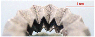
The key to disrupting conventional methods in producing PM components for various applications lies in achieving value-added complex components, such as the integration of cooling channels (shown in Fig. 1) to improve operational efficiency through topology optimization and material design.
Hence, there are ongoing studies to optimize the design of Interior PM (IPM) rotors.20–22 In this regard, spray forming, an alternate AM process has been successful in the fabrication of a design optimised motor with more than 40% higher power density and 15% lower losses.23 The same was achieved through the optimization of laser parameters, grain boundary infiltration, and laser exposure strategy.
In the operation of LPBF machines, several process parameters play pivotal roles, each significantly influencing powder behaviour during its spread and the properties of the final product. These parameters include laser power (P), measured in watts, scanning speed (ν) in mm s−1, hatch spacing (h) in mm, and layer thickness (t) in mm. These factors are critical in defining the geometry of the melt pool, shaping the thermal history, and affecting the energy distribution during the process. As a result, they have a direct impact on the microstructure, the residual stress levels, and the overall performance of additively manufactured NdFeB PMs.
3. Process parameters and printed part properties
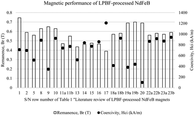
Process parameters in the literature where the LPBF of NdFeB magnets was studied are reported (Table 1) in attempt to enable reproducibility of research which is essential for scientific validation. Detailed parameter documentation can aid with the optimizing of the manufacturing process, enhancing the quality and properties of the magnets.The maximum remanence and coercivity values, which are crucial indicators of magnetic performance, from the studies listed in Table 1 are summarized in the Fig. 2.
| (A) Process parameters | ||||||||||||||
|---|---|---|---|---|---|---|---|---|---|---|---|---|---|---|
| S/N | Paper | Year | Ref. | Feedstock condition (MQP-S)/additive(s) used (pre/post-fabrication) | Processing parameters (w/optimised setting for magnetic performance italicized and in bold, if stated in paper), where some values are derived using eqn (1) and (2) or approximated from graphs in studies if values are not reported | |||||||||
| Laser power, P (W) | Scanning speed, v (mm s−1) | Hatch spacing, d (μm) | Layer thickness, t (μm) | Linear energy density, P/v (J mm−1) | Area energy density, P/(v × d) (J mm−2) | Volume Energy density, P/(v × d × t) (J mm−3) | Exposure time (μs) | Laser spot diameter (μm) | Exposure pattern | |||||
| Feedstock | ||||||||||||||
| 1 | Powder datasheet (feedstock MQP-S powder) | Not stated | 4 | As received | ||||||||||
| (a) Studies where final part composition is purely NdFeB | ||||||||||||||
| 2 | Net shape 3D Printed NdFeB permanent magnet | 2016 | 17 | — | — | — | 100 | 20–100, 20 | N.A. | N.A. | N.A. | 110 | 15–30, N.A. | — |
| (1700 mA w/laser focus and point distance of 30 μm) | ||||||||||||||
| 3 | Laser beam melting of NdFeB for the production of rare-Earth magnets | 2016 | 18 | Sieved <32 μm | 10–100 | 50–1400 | 15, 20, 25, 30, 35, 40, 50, 60, 70 | 20, 30, 70 | Stable window: 0.03–0.04 | — | — | — | 40 | — |
| 4 | Influences of process parameters on rare Earth magnets produced by laser beam melting | 2017 | 2 | Sieved <32 μm | 20 to 90, 75 | 200–3500, 2500 | 20, 70 | 20 | 0.03 | 1.50 | 75.00 | — | — | Meander |
| 5 | Influence of melt-pool stability in 3D printing of NdFeB magnets on density and magnetic properties | 2019 | 24 | — | 40, 60 | 160, 200 | 500 | 40, 60, 80, 100, 120 | 0.375 | 0.75 | 18.75 | — | 80 | — |
| 6 | Laser powder bed fusion of NdFeB and influence of heat treatment on microstructure and crack development | 2020 | 9 | — | 20, 30, 40, 50, 60 | 100, 150, 200, 300, 400, 500, 600 | 20, 30, 45, 60, 75, 100 | 30 | 0.20 | 6.67 | 222.22 | — | — | Cross hatch, with 67° rotation |
| 7 | Self-organized giant magnetic structures via additive manufacturing in NdFeB permanent magnets | 2020 | 8 | — | — | 270 | 100 | 20, 40, 60, 80, 100 | — | — | — | 110 | — | — |
| 8 | Laser powder bed fusion of Nd–Fe–B permanent magnets | 2020 | 11 | Sieved <40 μm | 50, 75, 100, 125, 150 (>200 not suitable) | 1000, 1500, 2000, 2500 | 35, 75 | 30 | — | 0.8–2.3 | — | — | 110 | — |
| 9 | Process–structure–property relationships in laser powder bed fusion of permanent magnetic Nd–Fe–B | 2021 | 6 | Sieved <75 μm | 100 (w/point distance of 65 μm) | — | 90, 100, 110, 120 | 30 | N.A. | N.A. | N.A. | 37, 44, 51, 58, 65, 72, 79, 86 | 40 | Meander |
| 10 | Microstructure and magnetic properties of Nd–Fe–B permanent magnets produced by laser powder bed fusion | 2021 | 10 | Sieved <40 μm | — | — | — | 30 | — | 0.5–2.4 | — | — | 110 | — |
| 11 | Fabrication of crack-free Nd–Fe–B magnets with laser powder bed fusion | 2022 | 25 | — | 26, 32, 39, 45 | 160 (focus laser), 200, 240 (defocus laser), 280 | 100 | 20 | — | 1.6 | 80 | — | — | Uni-directional with 90° rotation |
| (b) Studies where final part composition is not purely NdFeB (additives included pre/post-fabrication) | ||||||||||||||
| 12 | Additive Manufacturing of Bonded Nd–Fe–B—effect of Process parameters on magnetic properties | 2017 | 26 | Mixed with 34% volume of PA-12 (powder-form) pre-fabrication | 42, 52, 62 | — | 200, 300 | 50, 100, 150 | —0 | — | — | — | — | — |
| 13 | Coercivity enhancement of selective laser sintered NdFeB magnets by grain boundary infiltration | 2019 | 12 | — | 20–100 | 50–2000 | 100–140 | 20 | 0.03–0.07 | 0.0028–0.0042 (stable window for intact cubes) | 0.14–0.21 (stable window for intact cubes) | — | — | — |
| 14 | Coercivity enhancement of selective laser sintered NdFeB magnets by grain boundary infiltration | 2019 | 12 | Diffused with Nd70Cu30 post-fabrication | 20–100 | 50–2000 | 100–140 | 20 | 0.03–0.07 | 0.0028–0.0042 (stable window for intact cubes) | 0.14–0.21 (stable window for intact cubes) | — | — | — |
| 15 | Coercivity enhancement of selective laser sintered NdFeB magnets by grain boundary infiltration | 2019 | 12 | Diffused with Nd80Cu20 post-fabrication | 20–100 | 50–2000 | 100–140 | 20 | 0.03–0.07 | 0.0028–0.0042 (stable window for intact cubes) | 0.14–0.21 (stable window for intact cubes) | — | — | — |
| 16 | Coercivity enhancement of selective laser sintered NdFeB magnets by grain boundary infiltration | 2019 | 12 | Diffused with Nd60Al10Ni10Cu20 post-fabrication | 20–100 | 50–2000 | 100–140 | 20 | 0.03–0.07 | 0.0028–0.0042 (stable window for intact cubes) | 0.14–0.21 (stable window for intact cubes) | — | — | — |
| 17 | Coercivity enhancement of selective laser sintered NdFeB magnets by grain boundary infiltration | 2019 | 12 | Diffused with Nd50Tb20Cu20 post-fabrication | 20–100 | 50–2000 | 100–140 | 20 | 0.03–0.07 | 0.0028–0.0042 (stable window for intact cubes) | 0.14–0.21 (stable window for intact cubes) | — | — | — |
| 18 | Additive manufacturing of bulk nanocrystalline FeNdB based permanent magnets | 2021 | 27 | Sieved <63 μm, before mixed with Nd16.5–Pr1.5–Zr2.6–Ti2.5–Co2.2–Fe65.9–B8.8 (named P-RE-18) pre-fabrication | 200 | 2000 | 30 | 50 | 0.1 | 3.33 | 66.67 | — | 46 | Meander |
| 19 | Additive manufacturing of bulk nanocrystalline FeNdB based permanent magnets | 2021 | 27 | Sieved <63 μm, before mixed w/additives – Nd11.0–Pr1.0–Zr2.6–Ti2.5–Co2.4–Fe71.6–B8.8 (named P-RE-12) pre-fabrication | 200 | 2000 | 30 | 50 | 0.1 | 3.33 | 66.67 | — | 46 | Meander |
| 20 | Additive manufacturing of bulk nanocrystalline FeNdB based permanent magnets | 2021 | 27 | Sieved <63 μm, before mixed w/additives – Nd7.5–Pr0.7–Zr2.6–Ti2.5–Co2.5–Fe75.4–B8.8 (named P-RE-8) pre-fabrication | 200 | 2000 | 30 | 50 | 0.1 | 3.33 | 66.67 | — | 46 | Meander |
| 21 | Influence of powder loading fraction on properties of bonded permanent magnets prepared by selective laser sintering | 2021 | 28 | Mixed with polymer at 9 different loading fractions (between 10 to 90%) pre-fabrication | 1.01 | 29.17 | 110 | 100 | — | 0.255 | 2.55 | — | — | — |
| 22 | Fabrication of crack-free Nd–Fe–B magnets with laser powder bed fusion | 2022 | 25 | Mixed with 5% Pr–Nd–Cu (d50 = 10 μm) pre-fabrication | 26, 32, 39, 45 | 160, 200 (focus laser), 240, 280 (defocus laser) | 100 | 20 | — | 1.6 | 80 | — | — | Uni-directional with 90° rotation |
| 23 | Fabrication of crack-free Nd–Fe–B magnets with laser powder bed fusion | 2022 | 25 | Mixed with 5% Pr–Nd–Cu (d50 = 36 μm) pre-fabrication | 26, 32, 39, 45 | 160 (defocus laser), 200, 240, 280 (focus laser) | 100 | 20 | — | 1.6 | 80 | — | — | Uni-directional with 90° rotation |
| (B) Performance of printed parts | |||||||||||||
|---|---|---|---|---|---|---|---|---|---|---|---|---|---|
| S/N | Paper | Year | Ref. | Machine used | Build plate | Printed specimen shape and dimensions | Print performance (w/optimised result italicized and in bold) | ||||||
| Means of density measurement | Relative Density (%) w.r.t. NdFeB theoretical density of 7.6 g cm−3 | Magnet testing equipment | Remanence, Br (T) | Coercivity, Hci (kA m−1) | Max Energy Product, (BH)max (kJ m−3) | Polarization (mT) | |||||||
| Feedstock | |||||||||||||
| 1 | Powder datasheet (feedstock MQP-S powder) | Not stated | 4 | ≈98 (7.43 g cm−3) | 0.73–0.76 | 670–750 | 80–92 | ||||||
| (a) Studies where final part composition is purely NdFeB | |||||||||||||
| 2 | Net shape 3D printed NdFeB permanent magnet | 2016 | 17 | Model Realizer SLM 50 | Steel connected with a larger copper piece | 5 × 5 × 5 mm3 cube | Not stated | 92 | Pulsed field magnetometer (PFM) | 0.59 | 695 | 45 | N.A. |
| 3 | Laser beam melting of NdFeB for the production of rare-earth magnets | 2016 | 18 | Concept Laser Mlab Cusing | 1.4541 stainless steel | 5 × 5 × 5 mm3 cube | Dividing mass (in air) by known volume | 86 | Helmholtz coil w/fluxmeter | 0.51 | — | — | 513.6 |
| 4 | Influences of process parameters on rare Earth magnets produced by laser beam melting | 2017 | 2 | Concept Laser Mlab Cusing R | 1.4145 stainless steel | 5 × 5 × 5 mm3 cube | Dividing mass (in air) by known volume | 97 | Helmholtz coil w/fluxmeter | — | — | — | 550 |
| 5 | Influence of melt-pool stability in 3D printing of NdFeB magnets on density and magnetic properties | 2019 | 24 | Farsoon FS121M | 1.4301 stainless steel | 5 × 5 × 5 mm3 cube | Archimedes method (water displacement) | 90.9 | Brockhaus hystograph HG 200 w/measuring coil TJH 10 | 0.56 | 516 | 35.9 | — |
| 6 | Laser powder bed fusion of NdFeB and influence of heat treatment on microstructure and crack development | 2020 | 9 | DMG Mori Bielefeld GmbH | 1.4404 stainless steel | 5 × 5 × 5 mm3 cube | Image analysis | 96 | — | — | — | — | — |
| 7 | Self-organized giant magnetic structures via additive manufacturing in NdFeB permanent magnets | 2020 | 8 | Realizer SLM 50 | — | 7.5 × 7.5 × 7.5 mm3 cube and 35 mm OD torus | — | — | — | 0.45 | — | — | — |
| 8 | Laser powder bed fusion of Nd–Fe–B permanent magnets | 2020 | 11 | Concept Laser M2 | Steel substrate | 5 mm diameter × 5 mm height cylinder | Dividing mass (in air) by known volume | 90 | Permeagraph (magnetphysik GmbH) | 0.63 | 886 | 63 | — |
| 9 | Process–structure–property relationships in laser powder bed fusion of permanent magnetic Nd–Fe–B | 2021 | 6 | Renishaw AM125 | Mild steel | 10 mm diameter cylinder | Dividing mass (in air) by known volume | 91 | Permeagraph (magnetphysik GmbH) – post-magnetization in external 2T magnetic field | 0.65 | 346 | 62 | — |
| 10 | Microstructure and magnetic properties of Nd–Fe–B permanent magnets produced by laser powder bed fusion | 2021 | 10 | Concept Laser M2 | Steel substrate | Part | — | — | Permeagraph (Magnetphysik GmbH) | 0.63 | 921 | 63 | — |
| 11 | Fabrication of crack-free Nd–Fe–B magnets with laser powder bed fusion | 2022 | 25 | — | Aluminium alloy A6061 | 5 × 5 × 1.5 mm3 cuboid | Archimedes method (water displacement, with specimen coated with wax) | (i) 94.8 (defocus laser) (ii) 95.8 (focus laser) | Vibrating sample magnetometer (VSM, MS 1660) | (i) ≈0.47 (focus laser) (ii) ≈0.55 (defocus laser) | (i) ≈740 (focus laser) (ii) ≈770 (defocus laser) | (i) 41.0 (defocus laser) (ii) 43.0 (focus laser) | — |
| (b) Studies where final part composition is not purely NdFeB (additives included pre/post-fabrication) | |||||||||||||
| 12 | Additive manufacturing of bonded Nd–Fe–B—effect of process parameters on magnetic properties | 2017 | 26 | — | — | 10 mm diameter cylinder | — | 47 (3.6 g m−3) | — | — | — | — | — |
| 13 | Coercivity enhancement of selective laser sintered NdFeB magnets by grain boundary infiltration | 2019 | 12 | Farsoon FS121M LPBF Machine | Steel substrate | 5 × 5 × 5 mm3 cube | Dividing mass (in air) by known volume | 65 (pre-diffusion) | Superconducting quantum interface device vibrating sample magnetometer (SQUID-VSM) | 0.436 | ≈520 (0.653 T) | — | — |
| 14 | Coercivity enhancement of selective laser sintered NdFeB magnets by grain boundary infiltration | 2019 | 12 | Farsoon FS121M LPBF Machine | Steel substrate | 5 × 5 × 5 mm3 cube | Dividing mass (in air) by known volume | 100 (post-diffusion) | Superconducting quantum interface device vibrating sample magnetometer (SQUID-VSM) | 0.464 | ≈838 (1.053 T) | — | — |
| 15 | Coercivity enhancement of selective laser sintered NdFeB magnets by grain boundary infiltration | 2019 | 12 | Farsoon FS121M LPBF Machine | Steel substrate | 5 × 5 × 5 mm3 cube | Dividing mass (in air) by known volume | 65 (pre-diffusion) | Superconducting quantum interface device vibrating sample magnetometer (SQUID-VSM) | 0.475 | ≈774 (0.973 T) | — | — |
| 16 | Coercivity enhancement of selective laser sintered NdFeB magnets by grain boundary infiltration | 2019 | 12 | Farsoon FS121M LPBF Machine | Steel substrate | 5 × 5 × 5 mm3 cube | Dividing mass (in air) by known volume | 100 (post-diffusion) | Superconducting quantum interface device vibrating sample magnetometer (SQUID-VSM) | 0.466 | ≈858 (1.078 T) | — | — |
| 17 | Coercivity enhancement of selective laser sintered NdFeB magnets by grain boundary infiltration | 2019 | 12 | Farsoon FS121M LPBF Machine | Steel substrate | 5 × 5 × 5 mm3 cube | Dividing mass (in air) by known volume | 100 (post-diffusion) | Superconducting quantum interface device vibrating sample magnetometer (SQUID-VSM) | 0.39 | ≈1208 (1.518 T) | — | — |
| 18 | Additive manufacturing of bulk nanocrystalline FeNdB based permanent magnets | 2021 | 27 | — | — | 4 × 4 × 2 mm3 cuboid | — | — | PPMS-9T, quantum design, darmstadt, Germany | (i) 0.57 [as built] (ii) 0.58 [annealed 600 °C, 10 min] | (i) ≈414 (0.52 T) [as built] (ii) ≈923 (1.16 T) [annealed 600 °C, 10 min; 500 °C, 60 min] | (i) 48 [as built] (ii) 62.3 [annealed 600 °C, 10 min] | — |
| 19 | Additive manufacturing of bulk nanocrystalline FeNdB based permanent magnets | 2021 | 27 | — | — | 4 × 4 × 2 mm3 cuboid | — | — | PPMS-9T, quantum design, darmstadt, Germany | (i) 0.69 [as built] (ii) 0.70 [annealed 600 °C, 10 min] | (i) ≈382 (0.48 T) [as built] (ii) ≈438 (0.55 T) [annealed 600 °C, 10 min] | (i) 64.3 [as built] (ii) 68.1 [annealed 600 °C, 10 min] | — |
| 20 | Additive manufacturing of bulk nanocrystalline FeNdB based permanent magnets | 2021 | 27 | — | — | 4 × 4 × 2 mm3 cuboid | — | — | PPMS-9T, quantum design, darmstadt, Germany | ≈0.69 [as built] | ≈99 (0.125 T) [as built] | ≈30.4 [as built] | — |
| 21 | Influence of powder loading fraction on properties of bonded permanent magnets prepared by selective laser sintering | 2021 | 28 | Custom SLS machine | — | 14 mm diameter × 4 mm height cylinder | Dividing mass (in air) by known volume | Not reported (maximum achieved at 70 vol% loading fraction) | Hall effect-based measurement device in a field of 3.5 T | Not reported (maximum achieved at 70 vol% loading fraction) | — | — | — |
| 22 | Fabrication of crack-free Nd–Fe–B magnets with laser powder bed fusion | 2022 | 25 | — | Aluminium Alloy A6061 | 5 × 5 × 1.5 mm3 cuboid | Archimedes method (water displacement, with specimen coated with wax) | (i) 95.8 (defocus laser) (ii) 98.0 (focus laser) | Vibrating sample magnetometer (VSM, MS 1660) | (i) ≈0.56 (focus laser) (ii) ≈0.58 (defocus laser) | (i) ≈865 (focus laser) (ii) ≈915 (defocus laser) | (i) 55.7 (defocus laser) (ii) 49.0 (focus laser) | — |
| 23 | Fabrication of crack-free Nd–Fe–B magnets with laser powder bed fusion | 2022 | 25 | — | Aluminium Alloy A6061 | 5 × 5 × 1.5 mm3 cuboid | Archimedes method (water displacement, with specimen coated with wax) | (i) ≈96.6 (defocus laser) (ii) ≈97.2 (focus laser) | Vibrating sample magnetometer (VSM, MS 1660) | (i) ≈0.57 (focus laser) (ii) ≈0.59 (defocus laser) | (i) ≈870 (focus laser) (ii) ≈940 (defocus laser) | — | — |
This summary was created to aid in selecting an appropriate reference study for further investigation based on specific magnetic performance criteria. Notably, Fig. 2 reveals that high remanence in a printed part does not necessarily correlate with high coercivity, underscoring the complex relationship between these magnetic properties in LPBF-fabricated NdFeB magnets. However, it is worthwhile to note that a variety of magnetic measurement methods were used among the several studies summarised in Table 1, such as pulsed field magnetometer (PFM), Helmholtz coil w/fluxmeter, Brockhaus Hystograph, Permeagraph (Magnetphysik GmbH) and different models of vibrating sample magnetometers (VSM).
With regards to printed part characteristics, density is one of the critical properties to assess NdFeB magnets, owing to its direct influence on the magnet's polarization. This relationship stems from the proportion of NdFeB present within the volume, where a higher density typically indicates a greater concentration of this magnetic phase. The density of LPBF-processed NdFeB magnets (with minimally 0.85% relative density) is summarised in Fig. 3.
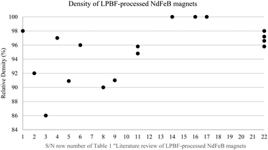 | ||
| Fig. 3 Density of LPBF-processed NdFeB magnets (multiple data points exist for some Row No. due to several parts in different conditions being reported). | ||
It was observed that the highest relative density (of 100%) LPBF-processed magnets is from a study which investigated coercivity enhancement through grain boundary infiltration (Rows No. 14, 16 and 17 of Table 1) The second ranked highest density value (of 98%) similarly came from a study which did not have a pure NdFeB composition, where they premixed the feedstock NdFeB powder with additives (Row No. 22 of Table 1). It was then shown in a separate study that high density (of 97%) without additives could also be achieved just through process optimisation and the use of feedstock powder sieved under 32 μm. However, it is important to note that the density for this and several other studies (as shown in Table 1) have used the straightforward division of weight by volume based on design specifications, it may not always reflect the true physical characteristics of the manufactured object, particularly if there are manufacturing defects or porosities. On the other hand, the Archimedes' principle is likely to provide a more direct measurement of the actual volume, leading to potentially more accurate density measurements for irregular or porous objects. Using Archimedes’ principle, a relatively lower density of 90.9% was reported (Row No. 5 of Table 1). However, in a separate study also using the Archimedes’ principle, a density of 95.8% was reported.
Precise control and optimization of various considerations can significantly influence the magnetic properties of the final product and the means of doing so is examined. The focus will be on effectively discussing process parameters for the influence of individual set processing parameters and resultant processing characteristics, namely the rate of solidification and resultant energy input from the combination of set processing parameters; laser power, scan speed, hatch spacing, layer thickness, exposure pattern and build orientation.
Energy density and rate of solidification are attributed by a combination of the different processing parameters and is discussed in the following section. In addition, the influence of processing parameters on the printed part's relative density and magnetic performance is discussed. Reference to the specific rows of Table 1 will be made in the following subsections to aid with discussion of several points on the topic of LPBF processing of NdFeB magnet.
In LPBF processing, the energy inputs can be represented in different ways such as liner energy density (EL), area energy density (EA) or volumetric energy density (EV) which can be calculated from the process variables using the following equations.10,29
 | (1) |
 | (2) |
 | (3) |
As a result of the use of different combinations of process parameters, there are two resultant variables namely, area energy density (EA) and volumetric energy density (EV). While EA is determined entirely by laser-specific parameters as shown in eqn (1), the EV as shown in eqn (2) also considers the non-laser parameter of the set layer thickness. On the other hand, line energy density (LED) does not consider both hatch spacing and set layer thickness, as it only considers that of one line. Upcominsubsections will briefly introduce the effects of these process variables on the LPBF processing of NdFeB PM. To give a broader perspective on the influence of process variables, literature references pertaining to common AM materials like Inconel 718 and AlSi10Mg are also summarized and cited when such studies are not widely ailable on NdFeB.
With reference to Row No. 8 of Table 1, Bittner et al.11 have found that the excessively large energy input for the material before part defects occur was at when area energy input went above 2.3 J mm−2. In their study, they have claimed that a laser power of 200 W or more was generally unsuitable for LPBF of NdFeB. However, it is noteworthy that the final applied energy density is not solely dependent on energy density alone and it is more meaningful to consider boundary conditions when determining maximum thresholds of a singular process parameters. In the same study, delamination within the sample itself is increasingly observed as energy input is raised, which can be seen in Fig. 4.11
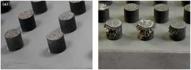 | ||
| Fig. 4 Examples of LPBF fabricated Nd–Fe–B samples; (a) cylindrical sample with suitable parameters between 0.8 and 2.3 J mm−2, (b) delamination caused by too high energy input above 2.3 J mm−2.11 | ||
With reference to Row No. 9 of Table 1, in a study by Wu et al.,6 they have explored the process–structure–property relationships in LPBF of NdFeB and have found that delamination could be minimized through use larger hatch spacing, but at the expense of the part's relative density. In their study, they have also found that exposure time (which directly influences resultant energy input) is closely relation to the final achieved density and whether processing defects such as fragmentation and delamination could occur when energy input outside the stable processing window is used. Fig. 56 depicts samples specimens produced with different processing parameters (exposure times and hatching distance).
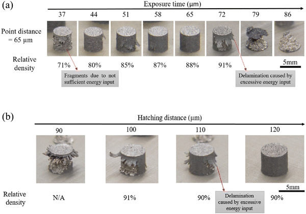 | ||
| Fig. 5 Density and form of samples produced with different process parameters which influence resultant energy input (a) exposure time (b) hatch spacing.6 | ||
In a process optimisation study on LPBF of NdFeB (screened to a smaller size range at sieve size of 40 μm) by Bittner et al.11 (Row No. 8 of Table 1), investigated the process window for NdFeB magnets. Here, an EA less than 0.6–0.8 J mm−2 resulted in the sintering of powder particles yielding a high porosity. On the other hand, a stable build was reported for EA between 0.8 and 2.3 J mm−2. Finally, they concluded that the risk of delamination tends to increase beyond the above-mentioned EA threshold.
The stable processing window guided primarily by energy density was also understood in a study by Kolb et al.18 (Row No. 3 of Table 1), where they have found that two primary factors restrict the window. These two factors are low line energies and wide hatch distances which result in incomplete cubes due to inadequate energy for fully remelting the powder. As line energies increase and hatch distances decrease, enhancing the energy input, the cubes' density improves. However, similar to the study by Bittner et al.10 and Kolb et al.18 (Rows No. 10 and 3 of Table 1 respectively), have found that beyond a certain point, the specimens begin to crack and their stability progressively diminishes as illustrated in Fig. 6.
 | ||
| Fig. 6 Specimens fabricated with different levels of energy density inputs (a) insufficient (b) suitable (c) excessive.18 | ||
Moreover, in a study by Wu et al.6 (Row No. 9 of Table 1), they have revealed that printing parts with diameters or widths of 10 mm or larger was more feasible without experiencing delamination compared to parts measuring 5 mm, as illustrated in Fig. 7(a) and (e).6 Within this 10 mm size category, it was achievable to produce samples of diverse shapes, including cubes, columns, rings, and cylinders, as depicted in Fig. 7(a)–(d).6 Among these, cubic samples exhibited more defects, like cracking and delamination, than cylindrical samples, as highlighted in Fig. 7(d) and (f).6
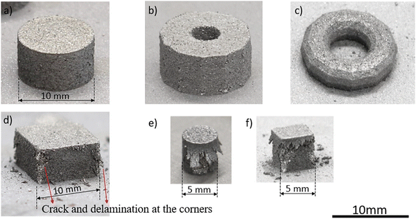 | ||
| Fig. 7 A range of geometrically shaped samples fabricated using an optimized parameter combination in L-PBF: (a) a cylindrical sample measuring 10 mm in diameter; (b) a hollow cylindrical sample with an external diameter of 13 mm and an internal diameter of 4 mm; (c) a ring-shaped sample with an external diameter of 14 mm and an internal diameter of 6 mm; (d) a cubic sample 10 mm wide; (e) a cylindrical sample with a 5 mm diameter; and (f) a cubic sample 5 mm wide.6 | ||
Wu et al.6 have attributed the observations to the fact that in larger components, the neighbouring tracks have more time to cool, leading to a lower temperature in the scanned area. Conversely, the periphery of smaller parts is subjected to higher temperatures and increased tensile stresses, which often result in larger cracks. Larger-volume samples have a more efficient energy distribution and transfer from the melt pool to the substrate plate compared to smaller ones. Consequently, the residual stresses in re-solidified samples with smaller dimensions are greater.
In the study by Wu et al.,6 they have found through the XRD patterns of both the initial feedstock powder and the material after processing that they primarily show an amorphous phase, peaks for Nd2Fe14B, and various precipitated phases as illustrated in Fig. 8.
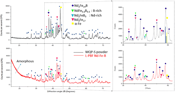 | ||
| Fig. 8 XRD patterns of LPBF-processed NdFeB samples – (top) initial feedstock powder (bottom) sample processed with optimized process parameters, showing crystalline phases.6 | ||
These precipitated phases are likely to be α-Fe, NdFe5.5B5.5 (boron-rich), Nd2–FeB3 (neodymium-rich), and Nd2Fe17, as identified by matching their XRD peaks. The primary phase, Nd2Fe14B, remains stable during laser processing.
Studies by Jacimovic et al.,17 Bittner et al.10 and Wu et al.6 (Rows No. 2, 10 and 9 of Table 1 respectively) have agreement in discovery that the initial powder's peaks correspond predominantly to Nd2Fe14B, except for a prominent peak at around 44.5°.3,6,10,17 The selective melting of powder particles completely alters the microstructure and results in the formation of soft magnetic α-Fe phases due to the excessive Fe content.12 This hence contributes to the deterioration in the hard magnetic properties.30 In this regard, recent research works highlighted the stabilization of Nd2Fe14B phase with minimal α-Fe segregation by fine-tuning the laser parameters for high cooling rates.8,11,30,31 While shallow laser melt pool (depth <50 μm) favours the rapid solidification and coercivities of up to 695 kA m−1 (0.87 T), 825 kA m−1 (1.04 T), and 886 kA m−1 (1.11 T),31 deeper melt pool (∼100 μm) resulted in slow solidification and a coarse microstructure with poor magnetic properties.30
The emergence and simultaneous presence of various phases in the Nd–Fe–B system can be understood through the equilibrium phase diagram depicted in Fig. 9.32
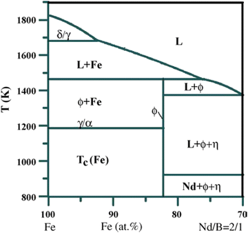 | ||
| Fig. 9 Schematic representation of the quasi-binary phase diagram of the Nd–Fe–B system, highlighting the crucial phase formations near the peritectic point.32 | ||
The MQP-S powder utilized in this process is composed of roughly 8% rare earth elements by atomic percentage, positioning it on the left side of the Nd2Fe14B boundary. In this section of the phase diagram, the desired hard magnetic phase F, Nd2Fe14B, does not form exclusively at any given temperature range. Instead, iron (Fe) is the predominant element in this scenario. As the system cools, Fe begins to solidify from the liquid phase, initiating its growth at temperatures higher than the peritectic point of 1181 °C. It is only when the temperature drops below this peritectic temperature that the formation of Nd2Fe14B phase commences. Both these phases then proceed to solidify and remain stable down to room temperature, ensuring the structural integrity of the material.
In a study by Bittner et al.10 on LPBF-processed NdFeB, they have understood by means of EDX that no distinct change in chemical composition is observed after LPBF when they compare that of the powder and the specimens printed at different area energy densities. The chemical composition of the powder and the printed specimen is shown in Table 2.
| Condition | Fe | Nd | Zr | Co | Ti | Pr |
|---|---|---|---|---|---|---|
| Powder | 70.8 | 18.2 | 4.3 | 2.4 | 2.2 | 2.1 |
| E A = 0.9 J mm−2 | 70.7 | 17.1 | 5.2 | 2.7 | 2.4 | 1.9 |
| E A = 1.9 J mm−2 | 70.6 | 17.0 | 5.3 | 2.7 | 2.5 | 1.9 |
Using area energy density (EA) as the key resultant output of set process parameter, Bittner et al.10 have also established the relationship between EA and magnetic performance, using the metric of magnetic polarization and magnetic field (measured using a Permeagraph – Magnetphysik GmbH, which uses fluxmeters and computer-aided measurement). It was observed that a higher applied EA results in an elevated magnetic performance as illustrated in Fig. 10.10
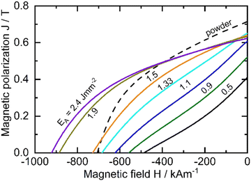 | ||
| Fig. 10 Established correlation between area energy density and magnetic property.10 | ||
Fig. 11 10 displays the XRD patterns of the original powder and two distinct LPBF-processed bulk magnets. The initial powder's peaks correspond predominantly to Nd2Fe14B, except for the prominent peak at 44.5°, which is attributed to α-Fe and overlaps with the 314 and 331 peaks of Nd2Fe14B. Post-LPBF, the notable α-Fe peak is absent, suggesting its elimination during consolidation. Additionally, the intensity of various Nd2Fe14B peaks is diminished post-LPBF, with some peaks poorly resolved, particularly in the 2θ range of 48° to 50°.
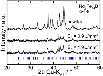 | ||
| Fig. 11 XRD patterns of LPBF-processed NdFeB samples – initial feedstock powder and samples processed at different area energy densities of 0.9 J mm−2 and 1.9 J mm−2.10 | ||
Bittner et al.10 (Row 10 of Table 1) discovered that the level of area energy input significantly impacts powder consolidation and melting. At lower energy inputs (as depicted in Fig. 9(a)10), the material exhibits only partial consolidation, characterized by a combination of melted regions, un-melted powder, and porosity, along with noticeable short cracks in the melted zones. In contrast, higher energy input results in enhanced density, as shown in Fig. 9(b).10 In this scenario, the sample displays no un-melted powder, yet the microstructure still contains cracks and pores. Notably, these cracks predominantly form in alignment with the build direction. Fig. 1210 presents the cross-sectional view of two different LPBF samples, illustrating these differences.
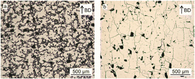 | ||
| Fig. 12 Cross-sectional images of samples printed at different area energy densities; (a) 0.9 J mm−2 (b) 1.9 J mm−2.10 | ||
Through a study by Jacimovic et al.17 (Row 2 of Table 1), which represented the first use of LPBF to fabricate NdFeB magnets, it was found that when EV increased by 5 times (as a result of LT decreasing from 100 to 20 μm as per eqn (3)), magnetic performance rose from a (BH)max of 15 to 45 kJ m−3. It was further ascertained that the fine-tuning of the processing parameters was the key enabler to produce dense magnets with fine grain sizes of approximately 1 μm.
Fine grain size in materials like NdFeB significantly enhances magnetic performance. Smaller grains allow for a higher degree of magnetic domain alignment, increasing remanence (residual magnetism). They also improve coercivity, the material's resistance to demagnetization, due to the increased grain boundary area, which impedes the movement of magnetic domains. Additionally, fine grains lead to more uniform magnetic fields, reduce eddy current losses in alternating magnetic fields, and offer better thermal stability.
Pelevin et al.33 have similarly found the correlation between EV and relative density of LPBF-processed NdFeB, where a larger EV is associated with achieving a higher relative density even when they have used a non-conventional double scan strategy. The dependence of relative density on EV is illustrated in Fig. 13.33
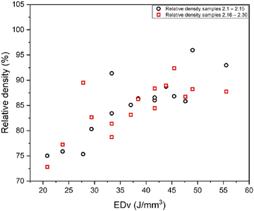 | ||
| Fig. 13 Influence of volumetric energy density (EDv) on relative density with proposed novel double scan strategy.33 | ||
With reference to Rows 4, 5, 6 and 11 where the highest printed specimen relative density was reported along with applied energy density,2,9,24,25 attempt was made to compare the correlation between energy density and printed part density across these four studies as shown in Fig. 14.
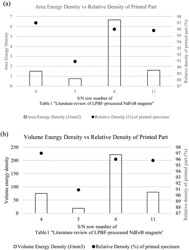 | ||
| Fig. 14 Comparison of correlation between energy density and printed part density across various studies with respect to (a) area energy density, (b) volumetric energy density. | ||
As depicted in Fig. 14, looking at these four studies, it was observed that the study from Row 4 with the highest applied EV did not yield the highest printed part density but the study from Row 5 with the lowest EV did indeed yield the lowest printed part density. On a separate note, however, similar applied energy has yielded very different reported printed part density when comparing that of the studies from Row 6 and 11 of Table 1. This would suggest that differences in the magnitude of the contributing individual processing (laser power, scan speed, hatch spacing and layer thickness) are likely to have influenced this result, therefore prompting the optimisation of these parameters for optimal density. In the case of studies from Row 6 and 11, although similar resultant EV was applied, different height of printed specimen and different sets of processing parameters were used, including scanning speed, hatch spacing and layer thickness. Nevertheless, when comparing Figures Fig. 14(a) and (b), they present similar trends with regards to the correlation between energy density and printed part density in each individual study.
In the scenario of slow solidification in a study by Jacimovic et al.17 (Row 2 of Table 1), the specimen exhibited poor magnetic properties, with coercivity (Hc) at 10 kA m−1, remanence (Br) at 0.05 T, and a maximum energy product ((BH)max) of just 0.1 kJ m−3. This performance is markedly inferior to the results observed in the case of rapid solidification, which achieved much higher values: Hc at 695 kA m−1, Br at 0.59 T, and (BH)max at 45 kJ m−3.
The microstructural outcome from slow and fast solidification where they are defined by the time taken for laser to move away from liquid pool in each scenario is more than 1 second and 100 μs respectively. As shown in Fig. 15, the contrast in microstructure resulting from slow and rapid solidification can be observed, with scanning electron microscope (SEM) images of the printed component produced under different process parameter sets.
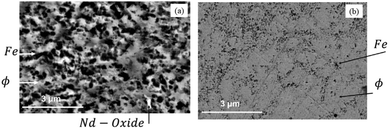 | ||
| Fig. 15 SEM images of samples printed at different rates of solidification; (a) slow solidification (b) fast solidification.17 | ||
Research has established that the microstructure and magnetic properties of 3D printed NdFeB parts are significantly impacted by the process parameters. These parameters play a crucial role in dictating how the molten powder solidifies, ultimately shaping the microstructure and influencing the magnetic characteristics of the final printed NdFeB parts.2,17,19,34 In samples printed where slow solidification occurred, three phases were identified using EDX mapping and XRD analysis, as shown in Fig. 16: Neodymium oxide, Fe and Nd2Fe14B (Φ).17
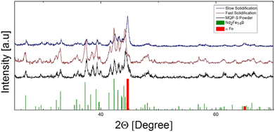 | ||
| Fig. 16 XRD patterns of LPBF-processed NdFeB samples – initial feedstock powder, samples processed at different rates of solidification, theoretical spectra of Nd2Fe14B and α iron (added as guidance).17 | ||
During slow solidification, the prolonged laser interaction, lasting over a second, leads to the formation of a deep liquid pool, roughly 100 mm deep. In this environment, small white regions indicative of neodymium oxide formation is observed. This oxide formation is likely due to the interaction between residual oxygen in the printing chamber (below 500 ppm) and the reactive rare earth metal.17
Neodymium oxide, being non-magnetic, facilitates easier reversal of magnetic domains, thereby reducing the coercivity. It also marginally lowers the remanence, correlating with the volume percentage of the hard magnetic phase in the specimen. Fe was identified in the cross section appearing in dark grey. The Fe precipitates, often dendritic and a few microns in size (up to 30 μm), contrast with the irregularly shaped Nd2Fe14B (Φ) phases which was identified in light grey. An abundance of Fe precipitates distributed across the sample volume implies that the actual density of the hard magnetic phase is considerably less than what is indicated by the measured volumetric density.20
In contrast, with rapid solidification, the laser exposure is brief, around 100 ms, resulting in a shallow liquid pool estimated at 20–30 μm deep. The correct laser power settings and the thin layer of powder deposition (20 μm) contribute to this shallow pool formation. Direct contact with the previously solidified material leads to rapid cooling, creating non-equilibrium conditions and significant undercooling of the melt.21
This process facilitates the formation of the peritectic Nd2Fe14B (Φ) intermetallic phase and effectively suppresses unwanted Fe precipitation. The inferior magnetic performance was found to be due to the material composition which differed when different rates of solidification was applied to the printed specimens.22,23
In contrast to samples that underwent rapid solidification, those processed with slow solidification exhibit a notably higher iron content in the Nd2Fe14B matrix. This increased iron presence detrimentally impacts the magnetic properties of the printed specimens in two primary ways. First, it lowers the total volume fraction of the hard magnetic phase, resulting in decreased remanence. The low Br value correlates with the noticeable presence of Fe. In addition, this would indicate that the actual density of the hard magnetic phase is considerably less than the measured volumetric density. Secondly, and more critically, coercivity is reduced, as the soft magnetic iron can promote the reversal of the magnetic domains of the hard magnetic phase.20
To facilitate rapid cooling rates and favourable melt pool dynamics in practical applications, heat sinks are required since the surrounding powder bed has a comparatively low thermal conductivity relative to bulk material. This can be achieved using supports, where surfaces with an angle greater than the critical angle δ (generally usually around 45° for most materials) would require support, as illustrated in Fig. 17.
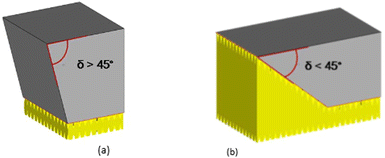 | ||
| Fig. 17 Use of supports depending on generally known critical angle of 45°.2 | ||
Support structures are essential for anchoring the workpiece to the building platform. They mechanically secure the workpiece, preventing displacement by the powder recoater during mechanical contact. To find the critical angle δ, where supports are needed for overhangs, Urban et al.2 built specimens with angles from δ = 20° to 60° using settings of 20 W and 400 mm s−1. This low energy input made it possible to build all specimens successfully without any support. However, this phenomenon may differ if a higher laser powder is applied.
In a study by Urban et al.,2 they have identified two support designs that enable rapid construction of support structures and allow for easy removal without damaging the part: block supports and tree supports. Block supports are constructed through single laser scan tracks to form slender walls, while tree supports are composed of slender cylinders arranged to create a structure resembling a tree. Limitations were found to exist with feasible choice of support geometry, particularly in the construction of thin walls, as evidenced in a study by Urban et al.2 This research indicated that building thin walls composed solely of single melt tracks was unfeasible, primarily due to their lack of sufficient mechanical strength to counteract internal tensions.
On the other hand, experiments conducted on hatched walls with thicknesses ranging from 0.2 to 1 mm and cylindrical structures with diameters from 0.5 to 2 mm, using low power density, were successful (with a relative density of between 55% and 65%). Interestingly, within a certain range, mechanical stability improved as density decreased. This phenomenon is attributed to crack formation within the material; specimens with higher overall density tended to exhibit larger cracks, thereby reducing mechanical stability.2
4. Conclusion
This study has thoroughly examined the effects of diverse process parameters on the LPBF of NdFeB alloys, emphasizing the critical importance of maintaining appropriate laser energy density to produce defect-free, high-density parts. The mapping of process windows has been instrumental in identifying parameter combinations that lead to optimal results, with recommended processing parameters and state-of-the-art magnetic performance metrics for LPBF-printed NdFeB alloys being summarized. The relationship between magnetic performance and material density, which is closely linked to microstructure, was highlighted. The study identified that the rate of solidification, influenced by parameters such as laser power, scan speed, hatch spacing, and layer thickness, plays a pivotal role in determining the microstructure. Specifically, two key factors—applied energy density of the laser and scan speed—were found to critically influence the rate of solidification and, consequently, the microstructure. It was further noted that achieving high-density, defect-free materials requires careful control of the applied area and volumetric energy densities. While increasing volumetric energy density by reducing layer thickness can improve density, it also introduces a trade-off: excessive energy density can lead to cracks that degrade magnetic performance, despite higher overall density. This underscores the complexity and precision required in LPBF processing for NdFeB magnets.5. Future perspectives
LPBF offers unmatched design flexibility and the ability to fabricate complex geometries, which are difficult to achieve with traditional manufacturing methods such as sintering or injection moulding. Moreover, LPBF allows for the customization of material properties at the microstructural level, offering a level of control that conventional techniques cannot easily replicate. However, the unique characteristics and complexities of the LPBF process mean that direct comparisons with traditional manufacturing methods are challenging, as standardized benchmarks for such comparisons are still evolving.The ability of LPBF to produce complex, lightweight, and robust components directly from powders aligns with the manufacturing industry's goals, positioning it as a key technology for the future of NdFeB magnet production.
• By overcoming current challenges through ongoing research and technological advancements, LPBF has the potential to revolutionize the design and manufacturing of high-performance NdFeB magnets, driving innovation and efficiency across various high-tech industries.
• Continued research is essential to enhance our understanding of the intricate interactions among the various LPBF process parameters, aiming to improve defect reduction, optimize mechanical properties, and expand industrial applications of LPBF-printed NdFeB alloys.
• Future studies will explore further prospects of LPBF, including topology optimization, near-net shape multi-material printing, and the development of novel alloys, which could further extend the capabilities and applications of LPBF in the production of NdFeB magnets.
Author contributions
Chan Yong Rong: writing – original draft preparation. Sankaranarayanan Seetharaman: conceptualisation, outlining, reviewing and editing second draft of manuscript. Jerry Ying Hsi Fuh and Lee Heow Pueh: reviewing of manuscript.Data availability
No primary research results, software or code have been included and no new data were generated or analysed as part of this review.Conflicts of interest
The authors declare that they have no known competing financial interests or personal relationships that could have appeared to influence the work reported in this paper.Acknowledgements
The authors gratefully acknowledge the funding support from Advanced Remanufacturing Technology Centre (ARTC), Singapore and National University Singapore (NUS). Yong Rong acknowledges the financial support from A*STAR Graduate Academy (AGA) Singapore, in the form of the A*STAR Graduate Scholarship (AGS), which supports his candidature for the Engineering Doctorate (EngD) offered by NUS.References
- V. Chaudhary, S. Mantri, R. Ramanujan and R. Banerjee, Additive manufacturing of magnetic materials, Prog. Mater. Sci., 2020, 114, 100688 CrossRef CAS.
- N. Urban, F. Huber and J. Franke, Influences of process parameters on Rare Earth Magnets produced by Laser Beam Melting, in 7th International Electric Drives Production Conference (EDPC), Wuerzburg, GERMANY, 2017, NEW YORK, IEEE, in International Electric Drives Production Conference, 2017, pp. 58–62. [Online]. Available: <Go to ISI >://WOS:000463734900009. [Online]. Available: <Go to ISI >://WOS:000463734900009.
- J. Jaćimović, F. Binda, L. G. Herrmann, F. Greuter, J. Genta, M. Calvo, T. Tomše and R. A. Simon, Net Shape 3D Printed NdFeB Permanent Magnet, Adv. Eng. Mater., 2017, 19, 1700098 CrossRef.
- Magnequench, MQP-S-11-9-20001 Powder Datasheet, https://mqitechnology.com/product/mqp-s-11-9-20001/, (accessed).
- H. Shipley, et al., Optimisation of process parameters to address fundamental challenges during selective laser melting of Ti-6Al-4V: A review, Int. J. Mach. Tools Manuf., 2018, 128, 1–20 CrossRef.
- J. L. Wu, N. T. Aboulkhair, M. Degano, I. Ashcroft and R. J. M. Hague, Process-structure-property relationships in laser powder bed fusion of permanent magnetic Nd–Fe–B, Mater. Des., 2021, 209, 11, DOI:10.1016/j.matdes.2021.109992 109992.
- T. K. Franke, et al. Laser Beam Melting of NdFeB for the production of rare-earth magnets, IEEE, 2016. [Online]. Available: https://ieeexplore.ieee.org/document/7851311.
- J. Jacimovic, T. Christen and E. Denervaud, Self-organized giant magnetic structures via additive manufacturing in NdFeB permanent magnets, Addit. Manuf., 2020, 34, 7, DOI:10.1016/j.addma.2020.101288 101288.
- N. Emminghaus, C. Hoff, J. Hermsdorf and S. Kaierle, Laser Powder Bed Fusion of NdFeB and influence of heat treatment on microstructure and crack development, Procedia CIRP, 2020, 94, 211–216 CrossRef.
- F. Bittner, J. Thielsch and W.-G. Drossel, Microstructure and magnetic properties of Nd–Fe–B permanent magnets produced by laser powder bed fusion, Scr. Mater., 2021, 201, 113921 CrossRef CAS.
- F. Bittner, J. Thielsch and W.-G. Drossel, Laser powder bed fusion of Nd–Fe–B permanent magnets, Prog. Addit. Manuf., 2020, 5(1), 3–9 CrossRef.
- C. Huber, et al., Coercivity enhancement of selective laser sintered NdFeB magnets by grain boundary infiltration, Acta Mater., 2019, 172, 66–71 CrossRef CAS.
- H. Wang, T. Lamichhane and M. Paranthaman, Review of additive manufacturing of permanent magnets for electrical machines: A prospective on wind turbine, Mater. Today Phys., 2022, 24, 100675 CrossRef CAS.
- R. Wrobel and B. Mecrow, A comprehensive review of additive manufacturing in construction of electrical machines, IEEE Trans. Energy Convers., 2020, 35(2), 1054–1064 Search PubMed.
- V. Popov, A. Koptyug, I. Radulov, F. Maccari and G. Muller, Prospects of additive manufacturing of rare-earth and non-rare-earth permanent magnets, Procedia Manuf., 2018, 21, 100–108 CrossRef.
- T. Pham, P. Kwon and S. Foster, Additive manufacturing and topology optimization of magnetic materials for electrical machines—A review, Energies, 2021, 14(2), 283 CrossRef CAS.
- J. Jacimovic, et al., Net Shape 3D Printed NdFeB Permanent Magnet, Adv. Eng. Mater., 2017, 19(8), 7, DOI:10.1002/adem.201700098 1700098.
- T. Kolb, et al., Laser Beam Melting of NdFeB for the production of rare-earth magnets, in 2016 6th International Electric Drives Production Conference (EDPC), IEEE, 2016,pp. 34–40.
- D. Goll, et al., Refining the Microstructure of Fe–Nd–B by Selective Laser Melting, Phys. Status Solidi RRL, 2019, 13(3), 1800536 CrossRef.
- D. Tsai, T. Chin, S. Hsu and M. Hung, The phase diagrams of the pseudobinary Nd-(Fe 14 B) and the Fe–Nd–B ternary system, IEEE Trans. Magn., 1987, 23(5), 3607–3609 CrossRef.
- D. Branagan and R. McCallum, Altering the cooling rate dependence of phase formation during rapid solidification in the Nd2Fe14B system, J. Magn. Magn. Mater., 1995, 146(1–2), 89–102 CrossRef CAS.
- Q.-Z. Jiang, M.-L. Zhong, Q.-C. Quan, J.-S. Zhang and Z.-C. Zhong, Striking effect of Hf addition on magnetic properties and thermal stability of Nd13Fe81− xB6Hfx (x= 0–1.0) alloys, J. Alloys Compd., 2016, 688, 363–367 CrossRef CAS.
- M. Jurczyk, Nd1.9M0.1Fe12Co2B, M= Ti or Hf as a material for permanent magnets, J. Magn. Magn. Mater., 1987, 67(2), 187–189 CrossRef CAS.
- M. Skalon, et al., Influence of Melt-Pool Stability in 3D Printing of NdFeB Magnets on Density and Magnetic Properties, Materials, 2020, 13(1), 14, DOI:10.3390/ma13010139 139.
- W.-Y. J. Jian, et al., Fabrication of crack-free Nd–Fe–B magnets with laser powder bed fusion, Materialia, 2022, 21, 101351 CrossRef CAS.
- A. Baldissera, P. Pavez, P. Wendhausen, C. Ahrens and J. Mascheroni, Additive manufacturing of bonded Nd–Fe–B—Effect of process parameters on magnetic properties, IEEE Trans. Magn., 2017, 53(11), 1–4 Search PubMed.
- D. Goll, F. Trauter, T. Bernthaler, J. Schanz, H. Riegel and G. Schneider, Additive Manufacturing of Bulk Nanocrystalline FeNdB Based Permanent Magnets, Micromachines, 2021, 12(5), 14, DOI:10.3390/mi12050538 538.
- M. Mapley, S. D. Gregory, J. P. Pauls, G. Tansley and A. Busch, Influence of Powder Loading Fraction on Properties of Bonded Permanent Magnets Prepared By Selective Laser Sintering, 3D Print. Addit. Manuf., 2021, 8(3), 168–175, DOI:10.1089/3dp.2020.0297.
- M. A. Buhairi, et al., Review on volumetric energy density: influence on morphology and mechanical properties of Ti6Al4V manufactured via laser powder bed fusion, Prog. Addit. Manuf., 2022, 1–19 Search PubMed.
- H. Kanekiyo, T. Miyoshi and S. Hirosawa, Nanocomposite magnet and method for producing same, ed: Google Patents, 2004.
- N. Urban, A. Meyer, S. Kreitlein, F. Leicht and J. Franke, Efficient near net-shape production of high energy rare earth magnets by laser beam melting, Appl. Mech. Mater., 2017, 871, 137–144 Search PubMed.
- O. Filip, R. Hermann, G. Gerbeth, J. Priede and K. Biswas, Controlling melt convection—an innovation potential for concerted microstructure evolution of Nd–Fe–B alloys, J. Mater. Sci. Eng. A, 2005, 413, 302–305 CrossRef.
- I. A. Pelevin, et al., New Scanning Strategy Approach for Laser Powder Bed Fusion of Nd–Fe–B Hard Magnetic Material, Metals, 2023, 13(6), 1084 CrossRef CAS.
- V. Chaudhary, S. A. Mantri, R. V. Ramanujan and R. Banerjee, Additive manufacturing of magnetic materials, Prog. Mater. Sci., 2020, 114, 38, DOI:10.1016/j.pmatsci.2020.100688 100688.
| This journal is © The Royal Society of Chemistry 2024 |

