
Dual strategies of mild C–F scissoring fluorination and local high-concentration electrolyte to enable reversible Li–Fe–F conversion batteries†
Yifan
Yu‡
abc,
Chuanzhong
Lai‡
abc,
Meng
Lei
abc,
Keyi
Chen
 ac and
Chilin
Li
*abc
ac and
Chilin
Li
*abc
aState Key Laboratory of High Performance Ceramics and Superfine Microstructure, Shanghai Institute of Ceramics, Chinese Academy of Sciences, 585 He Shuo Road, Shanghai 201899, China. E-mail: chilinli@mail.sic.ac.cn
bCenter of Materials Science and Optoelectronics Engineering, University of Chinese Academy of Sciences, Beijing 100049, China
cCAS Key Laboratory of Materials for Energy Conversion, Shanghai Institute of Ceramics, Chinese Academy of Sciences, Shanghai 201899, China
First published on 6th February 2024
Abstract
Batteries taking conversion-type iron fluorides as energy-dense cathodes provide the possibility for the power electrification of the transportation and aviation industries. However, a safe and low-toxicity synthesis method for fluorides and the design of a compatible electrolyte formula are still challenging. Here, we propose a dual strategy of mild C–F scissoring fluorination and a local high-concentration electrolyte (LHCE) to enable highly reversible Li–Fe–F conversion batteries. A facile and safe scissoring strategy at a low temperature (95 °C) enables the preparation of a carbon–iron fluoride composite with a porous cubic cage-like structure. CFx plays a double role as a solid fluorination agent and an in situ conductive network after defluorination. The as-prepared fluoride cathode delivers a reversible capacity as high as 300 mA h g−1 over 100 cycles. The further LHCE strategy not only enhances the oxidation stable voltage of the electrolyte (>5 V) and the transference number of Li+ (0.74), but also realizes dual protection of the fluoride cathode and Li metal anode by facilitating the construction of robust cathode– and anode–electrolyte interfaces, respectively. The LHCE-assisted fluoride battery releases a higher reversible capacity of 335 mA h g−1 after 130 cycles. This work provides a solution to high-performance carbon–fluoride conversion cathodes by a synergetic effect of tailored synthesis, electroactive particle texture and electrolyte formula.
New conceptsConventional lithium-ion batteries with oxide cathodes based on single-electron transfer are insufficient to meet the demand of high energy density. Iron-based fluoride, as a conversion-reaction-type cathode material, shows the merits of low cost and high energy density due to the multielectron transfer mechanism. However, the effective and safe synthesis strategy of iron fluoride and the design of the corresponding compatible electrolyte formulation are lacking. In this work, we firstly propose a facile and low-toxicity mild C–F scissoring strategy at a low synthesis temperature of 95 °C to prepare carbon–iron fluoride composites with a porous cubic cage-like morphology. In this synthesis, CFx plays a double role as a solid fluorination agent and in situ conductive network after defluorination. And benzylamine facilitates the hydrodefluorination of CFx apart from serving as the reaction medium. The low-toxicity FeCl3 not only serves as the iron source, but also promotes the ability of benzylamine to defluorinate CFx. To further alleviate the loss of active material, a strategy of local high-concentration electrolyte (LHCE) is proposed. The LHCE realizes dual protection of fluoride cathode and Li metal anode by facilitating the construction of a robust cathode electrolyte interface and SEI, respectively, leading to a high reversible capacity of 335 mA h g−1 after 130 cycles. |
Introduction
To achieve the goals of peak carbon and carbon neutrality as soon as possible, it is of great importance to reduce the emissions of greenhouse gases. The power electrification of vehicles and aircraft is an effective way to solve the emission of exhausts from transportation and aviation industries. However, conventional lithium-ion batteries based on Ni-rich layered oxide cathodes and graphite anodes only reach an energy density of 250–300 W h kg−1,1 which is insufficient to meet the demands of these applications. It is known that the power source of batteries stems from the cathodes. Compared with an intercalation cathode with limited capacity due to single-electron transfer, the conversion cathode FeF3 shows a theoretical capacity of 712 mA h g−1 benefitting from the characteristic three-electron transfer per Fe atom.2 Combined with the high theoretical voltage caused by the strong ionicity of the Fe–F bond, FeF3 enables a theoretical energy density as high as 1947 W h kg−1, making the material a potential cathode candidate for a high-specific-energy-density battery.3 Besides, the greater abundance of iron compared to nickel and cobalt makes FeF3 more competitive in terms of cost.4 However, the strong ionicity of the Fe–F bond is a double-edged sword. While endowing a high theoretical voltage, it also gives FeF3 electronic insulation. Therefore, the construction of electronically conductive networks is highly desirable to activate FeF3. However the development of a tailored synthesis strategy with compact conductive wiring is still a big challenge.Conductive carbon as a good electronic wire often participates in the construction of conductive networks. An initial attempt was made by the high-energy milling of ReO3-type FeF3 and conductive carbon.5 However, nanonization of the particles triggers a high surface energy, which makes the interface less stable and then leads to particle aggregation. In this case, the volume change of fluoride triggered by the phase transformation during cycling may lead to detachment between the uniformly distributed carbon and active materials. Subsequently, single-wall carbon-nanotube-derived electron arteries were constructed by an ionic liquid (IL) method to decorate hexagonal-tungsten-bronze-type (HTB) FeF3·0.33H2O and pyrochlore-type FeF2.5·0.5H2O.6 However, this method needs a precursor solution to wet the doped electron conductors. Recently, an electron-conductive network for FeF3 with a 3D honeycomb architecture was prepared by the pyrolysis of the polymer at 700 °C.7 Although this structure brings some advantages, e.g., sufficient pathways for electron transfer and Li-ion diffusion and suppression of unfavorable volume change, the fluorination process with toxic gas (NF3) is risky.
Therefore, the ideal synthesis of an FeF3 cathode with a well-defined electron-conductive network should satisfy the following requirements: (1) the whole preparation process should be less toxic or even non-toxic; (2) the electrode structure should provide efficient pathways for electron and ion transport and should tolerate the volume change; (3) the active material should be well dispersed in the electron conductor matrix. Accordingly, conventional fluorinating agents in gaseous (e.g., anhydrous HF, NF3 and F2) or liquid form (e.g., HF aqueous or alcohol solution) with highly toxic/corrosive properties are not considered. Although the fluoride salts (e.g., NH4F, NH4HF2 and KF) used as solid fluorinating agents can improve the safety of the synthesis process, the introduction of impurity cations may produce other inactive metal fluorides, which are difficult to separate from FeF3. The IL fluorination methods proposed by Li et al. for the synthesis of different FeF3 mineral phases (e.g., HTB-FeF38,9 or pyrochlore FeF3·0.5H2O10) are less toxic and corrosive. However, these regular fluorination synthesis methods all need the additional introduction or construction of a conductive network.
CFx as a solid fluoride is expected not only to serve as a safe solid fluorinating agent, but also to play the role of an in situ conductive matrix after defluorination. Reddy et al. proposed a non-toxic fluorination for the synthesis of iron fluoride derived from CFx considering that the liquid iron source (iron pentacarbonyl) can react with CFx at a high sintering temperature of 250 °C. The high toxicity of Fe(CO)5 is daunting and the enhanced ambience temperature would increase the F corrosion risk.11 Here, we propose a mild C–F scissoring strategy at a much lower temperature of 95 °C to prepare carbon–iron fluoride composites with a porous cubic cage-like structure. This one-pot fluorination method is facile and safe. Firstly, a regular low-toxicity iron salt (FeCl3·6H2O) and CFx are employed as the solid iron(III) source and fluorine source, respectively. In order to enhance the reactivity between FeCl3 and CFx, it is indispensable to break the C–F bond to provide free fluoride ions. Therefore, the second step is the hydrodefluorination of CFx accompanied by the in situ formation of an electron-conductive network (i.e., sp2 carbon), which is realized by the redox reaction between CFx and an organic amine (benzylamine). This reaction proceeds through proton coupled electron transfer (PCET) steps with the production of NH3,12 which leads to the formation of a complicated fluoride with iron (e.g., (NH4)3FeF6). Hence, the final step is heat treatment in an inert atmosphere to remove the NH4 cations and obtain pure iron fluorides, as illustrated in Fig. 1. The gasified NH3 escaping from the fluoride lattices during the heating process benefit the morphological modulation of iron fluoride into a porous cubic cage-like structure. This iron fluoride cathode enables a reversible capacity as high as 300 mA h g−1 after 100 cycles at 100 mA g−1. The strategy of a localized high-concentrated electrolyte (LHCE) further promotes the electrochemical performance by a dual interfacial protection mode in both the cathode/electrolyte interface (CEI) and anode/electrolyte interface (SEI). This mode lets the cathode behave with a higher reversible capacity of 335 mA h g−1 after 130 cycles at 100 mA g−1.
 | ||
| Fig. 1 Schematic illustration of the synthesis principle and reaction mechanism to prepare iron-based fluorides by mild C–F scissoring fluorination. | ||
Results and discussion
Synthesis and characterization of iron fluorides
The synthesis of iron-based fluorides is performed by a one-pot method based on the hydrodefluorination of CFx, which is followed by an annealing step to remove the NH4+ cations and H2O molecules in the fluoride lattice (Fig. 2(a)). The degassing process leads to the construction of a porous structure. As shown in Fig. 1, CFx firstly attracts an electron from benzylamine and then releases a free F− with the formation of an sp2 carbon. The oxidated benzylamine undergoes a series of PCET steps and then releases an NH3 molecule. Simultaneously, the presence of FeCl3 enhances the activity of benzylamine due to the potential catalytic effect,13 leading to complete conversion of CFx to amorphous carbon even at a mild temperature of 95 °C (Fig. S1, ESI†). In the case of the presence of FeCl3, the appearance of a significant D-band (1350 cm−1) and G-band (1590 cm−1) represents the breathing mode of the carbon rings and the stretching mode of C–C sp2 species, respectively, demonstrating a high degree of sp2 and therefore high electronic conductivity of defluorinated CFx (Fig. S2, ESI†).14 The Fe3+ cation from FeCl3 combines with the free F− as well as NH3 molecules, leading to the formation of (NH4)3FeF6, as shown in the X-ray diffraction (XRD) pattern (Fig. S3, ESI†). The dissolved Fe3+ is prone to absorption on the surface of nanocarbon from the defluorination of CFx and it benefits the tight contact between iron-based fluoride domains and conductive carbon wires. Therefore, there is no requirement for the introduction of a conductive additive.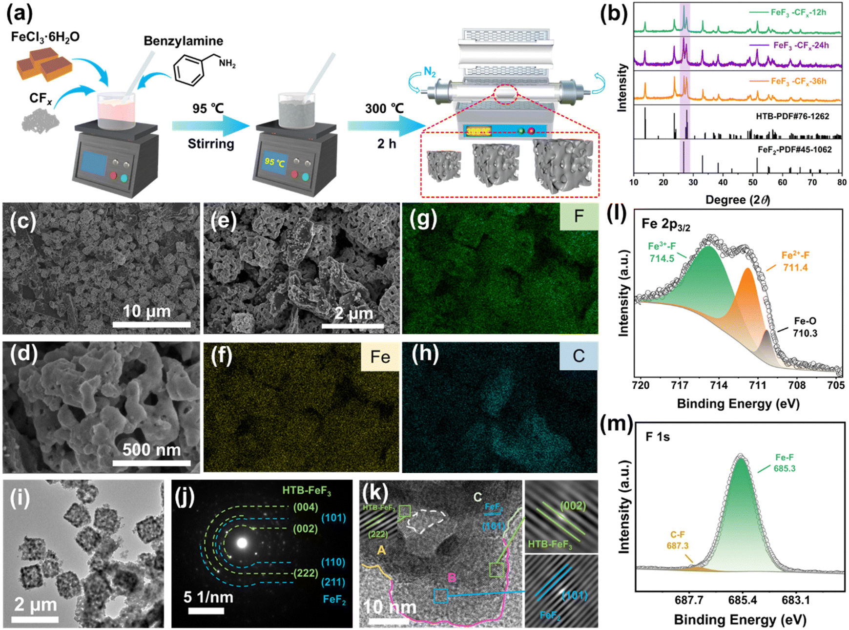 | ||
| Fig. 2 Structure and morphology of iron-based fluorides. (a) Schematic illustration of the synthesis of iron-based fluorides. (b) XRD patterns of FF-12, FF-24 and FF-36. (c)–(e) SEM images of iron-based fluorides at different scales. EDS mapping of (f) Fe, (g) F and (h) C elements corresponding to the area in (e). (i) TEM image, (j) SAED pattern and (k) HRTEM image of FF-24. Enlarged images of lattice spacings from ‘A’, ‘B’ and ‘C’ areas in (k) correspond to the (222) plane of HTB-FeF3, (101) plane of tetragonal FeF2 and (002) plane of HTB-FeF3. The area surrounded by a white dashed line represents the internal channel in the secondary particle. XPS spectra of (l) Fe 2p3/2 and (m) F 1s for FF-24. | ||
The removal of NH4+ filler from (NH4)3FeF6 was carried out by an annealing process at 300 °C for 2 h in an N2 atmosphere. Accompanied by the escape of NH3 gas from the interior of the fluoride particles, a porous structure is formed. According to the reaction time of the one-pot method, the final examples are denoted FF-12 (12 h), FF-24 (24 h) and FF-36 (36 h). The corresponding XRD patterns (Fig. 2(b)) show that the final products are composed of hexagonal-tungsten-bronze (HTB) FeF3 and tetragonal FeF2. The ratio of FeF3 and FeF2 is highly associated with the fluorination time, and the ratio of HTB-FeF3 increases with the increase in reaction time. Note that in (NH4)3FeF6 intermediate product, the rich NH4+ fillers retard the approach and linkage of FeF6 octahedra, and the ordered discrete distribution of 0D FeF6 octahedra is favorable for the preservation of an open framework structure during the gradual release of NH4+ fillers.15 Therefore the decomposition of (NH4)3FeF6 leads to the formation of an HTB-FeF3 phase with a 1D open tunnel structure after undergoing the ordered linkage and chaining of FeF6 octahedra. Note that the adjacent carbon wires are responsible for the partial reduction of HTB-FeF3 to FeF2 during the heating process. Note that the blending of the FeF2 phase is favorable for electrochemical cycling in view of its narrower band gap and more stable topotactic conversion reaction mechanism than those of FeF3.16
An initial screening for the optimized material was performed by looking at the cycling performance in a regular ether electrolyte containing 1 M lithium bis(trifluoromethanesulfonyl)imide (LiTFSI) dissolved in a mixed solvent of 1,3-dioxolane (DOL) and dimethyl ether (DME) (v/v, 1![[thin space (1/6-em)]](https://www.rsc.org/images/entities/char_2009.gif) :1), which is denoted LDD. As illustrated in Fig. S4 (ESI†), the FF-24 cathode shows the best rate performance compared with FF-12 or FF-36. This comparison indicates that increasing the FeF2 content to a certain degree can improve the rate performance, since the amount of LiF produced from FeF2 in the conversion process is lower and it can promote the penetration of the in-built mixed conductive network with Fe nanodomain chains.17 The hindrance of charge and mass transfers for the high-efficiency conversion of internal active materials becomes smaller. As the reaction proceeds, the oxidation of Fe2+ to Fe3+ would further activate the splitting of LiF and thus improve the reversible capacity and cycling performance. However, due to the two-electron transfer, the theoretical capacity of FeF2 is lower than that of FeF3. Therefore the excessively high content of FeF2 in the mixed fluorides (as in FF-12) would cause a decrease in the overall discharge capacity. Accordingly, further investigation for this iron fluoride composite cathode was undertaken on the optimized sample (i.e., FF-24), as discussed later.
:1), which is denoted LDD. As illustrated in Fig. S4 (ESI†), the FF-24 cathode shows the best rate performance compared with FF-12 or FF-36. This comparison indicates that increasing the FeF2 content to a certain degree can improve the rate performance, since the amount of LiF produced from FeF2 in the conversion process is lower and it can promote the penetration of the in-built mixed conductive network with Fe nanodomain chains.17 The hindrance of charge and mass transfers for the high-efficiency conversion of internal active materials becomes smaller. As the reaction proceeds, the oxidation of Fe2+ to Fe3+ would further activate the splitting of LiF and thus improve the reversible capacity and cycling performance. However, due to the two-electron transfer, the theoretical capacity of FeF2 is lower than that of FeF3. Therefore the excessively high content of FeF2 in the mixed fluorides (as in FF-12) would cause a decrease in the overall discharge capacity. Accordingly, further investigation for this iron fluoride composite cathode was undertaken on the optimized sample (i.e., FF-24), as discussed later.
The Rietveld refinement of the XRD pattern of FF-24 confirms the accurate composition, and the mass proportions of HTB-FeF3 and tetragonal FeF2 are 65% and 35%, respectively (Fig. S5, ESI†). The morphology of FF-24 is examined with the scanning electron microscopy (SEM) images, as shown in Fig. 2(c)–(e) and Fig. S6 (ESI†). The FF-24 product is composed of micron-sized (1 μm) porous cubic cage-like secondary particles self-assembled from many nanoscale primary particles. This interesting texture benefits the deep penetration of electrolyte into the interior of the micron-sized secondary particles and enhances the ion transport inside the fluoride cathode by a 3D ion diffusion pathway. This morphology would enrich the reaction sites and activate more capacity release. Moreover, such a hollow structure can accommodate the volume change during the conversion reaction and maintain the integrity of the cathode. The corresponding energy dispersive spectra (EDS) mapping (Fig. 2(f)–(h)) shows that the C signal can be well tracked with Fe/F signals, suggesting compact wiring of conductive carbon on fluoride grains. The enriched area of the C mapping signal stems from the excessive carbon particles (as shown in Fig. 2(e)).
Further confirmation of phase distribution and chemical composition was carried out by transmission electron microscopy (TEM) and X-ray photoelectron spectroscopy (XPS), respectively. The TEM image also reflects the well-defined porous cubic cage-like morphology of FF-24 (Fig. 2(i) and Fig. S7, ESI†). The diffraction rings correspond to the characteristic planes of HTB-FeF3 and tetragonal FeF2 in the selected area electron diffraction (SAED) pattern (Fig. 2(j)), further determining the coexistence of two fluoride phases. The high-resolution TEM (HRTEM) image (Fig. 2(k) and Fig. S8, ESI†) displays an alternative distribution between HTB-FeF3 and tetragonal FeF2 nanodomains as well as the internal channel of the secondary particle. The alternative phase distribution contributes to the enriched nanophase interfaces, which are expected to optimize the built-in conduction network close to the checkerboard distribution during the conversion reaction.18 The FeF2 nanodomains with a delayed conversion reaction can buffer the prior conversion of lithiated HTB phase. The F-anion framework stabilization effect from the topotactic conversion mechanism of FeF2 can better confine the conversion products of the dominant HTB-FeF3.16 These factors are responsible for the cycling stabilization and kinetic improvement of the FF-24 cathode. In the Fe 2p3/2 spectrum of FF-24 (Fig. 2(l)), peaks of Fe3+–F at 714.5 eV and Fe2+–F at 711.4 eV are observed, also indicating the coexistence of HTB-FeF3 and tetragonal FeF2 in FF-24.19 The minor peak at 710.3 eV is assigned to Fe–O, which should stem from O doping during the heating process. The O doping in the fluoride lattices is also confirmed by the appearance of the O signal in the overview spectrum (Fig, S9a, ESI†) and the peak at 530.5 eV in the O 1s spectrum (Fig. S9b, ESI†).20 In the F 1s spectrum (Fig. 2(m)), the peak at 685.3 eV corresponds to the Fe(II)/(III)–F signal. The binding energy difference between FeF2 and FeF3 is only 0.1 eV for Fe–F bonding, and it is hard to distinguish clearly.21 The C–F signal can be discerned from the peaks at 687.3 eV in the F 1s spectrum and at 289.0 eV in the C 1s spectrum (Fig. S9c, ESI†).22,23 The weak intensity of C–F indicates an almost complete defluorination of CFx. The C–N signal at 285.7 eV may originate from the derivative of residual amines. Additionally, the H2O adsorbed from the air and the O–H from the H2O in the channel of HTB-FeF3·0.33H2O are responsible for the two peaks at 533.9 eV and 532.3 eV, respectively.20,24
Electrochemical performance of FF-24 in ether electrolyte
Considering the potential Li storage in the defluorinated product of CFx, it is indispensable to exclude the capacity contribution of this carbonaceous product in order to evaluate the real capacity of iron-based fluorides. The defluorinated product of CFx was obtained by an acid cleaning method (ESI†). Obviously, the defluorinated products without and with FeCl3 participation show different electrochemical behavior in LDD electrolyte (Fig. S10, ESI†). The former (without the participation of FeCl3) displays a typical initial discharge behavior similar to that of CFx, which is associated with the formation of a hard-carbon structure with less sp2 content and crystalline LiF particles.14,25 Its reversible capacity is merely around 100 mA h g−1 and the corresponding voltage curves are sloped without a distinct conversion reaction plateau (Fig. S10a, ESI†). The latter (with the participation of FeCl3) shows electrochemical curves similar to the lithium insertion behavior in carbon with a smaller reversible capacity close to 60 mA h g−1 (Fig. S10b, ESI†).26 This also indirectly reflects the catalytic effect of FeCl3 on the defluorination of CFx. These capacities are much smaller than that of FF-24, confirming the dominant capacity contribution of HTB-FeF3 and tetragonal FeF2.After excluding the capacity contribution of the defluorinated product of CFx, the electrochemical behavior of FF-24 is exhibited in Fig. 3. The FF-24 conversion cathode enables an initial discharge capacity exceeding 600 mA h g−1 at 100 mA g−1 and the reversible capacity is still preserved at 542 mA h g−1 during the 2nd cycle. After operating for 100 cycles, the discharge capacity is still as high as 300 mA h g−1. The Coulombic efficiency (CE) is well maintained at close to 100% over 100 cycles. The reversible capacities of FF-24 are still as high as 474.6, 452.1, 392.6 and 347.9 mA h g−1 at the higher current densities of 200, 300, 500 and 1000 mA g−1, respectively (Fig. 3(a)). From the galvanostatic charge–discharge curves in Fig. 3(b), a discharge behavior with two-stage plateaux is observed, resulting from the intercalation reaction in the 3 V zone and the conversion reaction in the 2 V zone. The conversion-reaction plateau is well preserved during long-term cycling, benefitting from the optimization of ion and electron transfer paths in FF-24. As discussed above, the active material is composed of porous cubic-like secondary particles assembled from primary nanoparticles, which significantly promotes the infiltration of the electrolyte inside the active material. The electrochemical grinding is responsible for the further optimization of the built-in conductive network and for reviving ‘dead’ LiF zones. This effect is favorable for improvement of the conversion reaction kinetics and therefore enhancement of the discharge plateau during cycling. Simultaneously, in view of the large specific area of primary nanoparticles, the circumscription between surface and bulk phase becomes difficult to distinguish. Therefore, the charge transfer process of Li+ in the electrode network tends to be a capacitive-dominant process instead of a diffusion-controlled process, which benefits a reduction in voltage hysteresis. To evaluate the reaction kinetics of FF-24, cyclic voltammetry (CV) and the galvanostatic intermittent titration technique (GITT) were employed. In the CV curves under all scan rates, the two cathodic peaks are better separated than those during the anodic process due to the asymmetric conversion reaction paths between charge and discharge (Fig. 3(c)). Variation in scan rate does not induce a significant change in the positions of the redox peaks (even at the fastest scan rate of 1 mV s−1), indicating the fast migration of Li+ in the system. In the CV measurement, the current response of i(V) and scan rate v follow the law: i(V) = avb, where V is the independent variable of potential and a and b are adjustable parameters.27,28 The value of b ought to be located in the range 0.5–1.0 in the case of the presence of hybrid properties of pseudo-capacitance and diffusion. If b is close to 0.5, the process is diffusion-controlled (that is, it is based on faradaic intercalation). In contrast, the process is dominated by capacitance if b is close to 1.0.27 The b values for the four redox peaks can be obtained from linear fitting of log (peak current) vs. log (scan rate) (Fig. 3(d)). Obviously, the values of b corresponding to the four peaks are all located in the range 0.5–1.0, suggesting that all the intercalation and conversion reaction processes are controlled by both pseudo-capacitance and diffusion. To quantitatively describe the proportion of pseudo-capacitance, the formula i(V) = k1v + k2v1/2 is employed, where k1v and k2v1/2 represent the capacitance effect and faradaic intercalation process, respectively.29 Fig. S11 (ESI†) displays a typical CV profile at 0.4 mV s−1 with the capacitive current response (k1v) outlined in the green area. The ratios of different charge storage contributions at various scan rates are summarized in Fig. 3(e). The pseudo-capacitance contribution is more than half of the total charge storage, indicating that more faradaic processes occur on the surface of the active material during charge and discharge and therefore the reaction kinetics is accelerated.
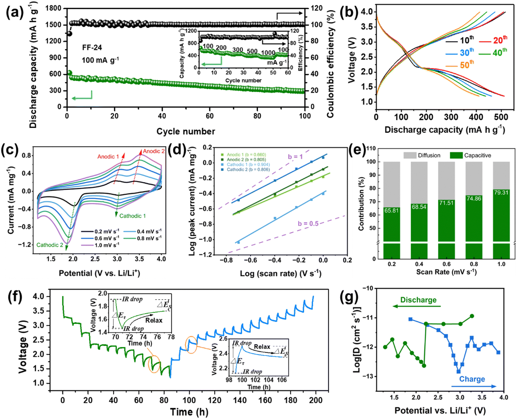 | ||
| Fig. 3 Electrochemical performance and reaction kinetics of iron-based fluorides in LDD electrolyte. (a) Cycling performance of the FF-24 cathode and (b) corresponding galvanostatic charge and discharge curves at different cycle stages at 100 mA g−1. Inset of (a): rate performance of FF-24 cathode. (c) CV curves of the FF-24 cathode at different scan rates. (d) Plots of the relationship between log(peak current) and log(scan rate) for different redox peaks in (c). (e) Column diagram of pseudo-capacitive contribution from the total charge storage capacity at various scan rates. (f) GITT curves of the FF-24 cathode during discharge and charge processes. Insets of (f): one-time titration steps during charge and discharge processes. (g) Calculated Li diffusion coefficients from the GITT test depending on different reaction voltages during discharge and charge. | ||
To further characterize the diffusion process of Li+ inside the electrode, GITT technology was used to calculate the diffusion coefficient of Li+ (D).30 A pre-cycle operation at 100 mA g−1 for 3 cycles was performed to let the conversion reaction cells reach a steady state. Subsequently, the cells were operated at 30 mA g−1 for an intermittent time of 1 h, followed by a relaxation process of 6 h without application of a current (Fig. 3(f)). The two insets in Fig. 3(f) show the detailed view of a single GITT step for FF-24 during discharge and charge processes, respectively. The sudden voltage decrease (i.e., IR drop) at the initial stage in the relaxation process represents the overpotential induced by the ohmic resistance and charge transfer resistance at the electrode/electrolyte interface. ΔEτ represents the voltage difference between the beginning and termination states in one GITT step. Considering that the Li+ diffusion obeys the second Fick's law of diffusion and there is a linear relationship between transient potential (Eτ) and the square root of intermittent time (τ1/2) (Fig. S12, ESI†), the D value can be calculated with the following equation:31
The development of local high-concentration electrolytes for FF-24
The dissolution of transition metal into electrolyte caused by the unstable CEI layer is a potential problem for conversion-type fluoride cathodes. Therefore, apart from the construction of a high-performance cathode with a unique structure, the establishment of a robust CEI/SEI layer also has benefits for upgrading of the electrochemical performance of iron fluorides. Therefore, we developed a local high-concentration electrolyte (LHCE) strategy for fluoride conversion cathodes to realize the performance goal for the first time. The LHCE system not only retains the advantages of high-concentration electrolytes (e.g., high-voltage stability, high cation transport efficiency, and special interface chemistry), but also shows some unique characteristics (e.g., low cost and viscosity) due to the introduction of a non-coordinating co-solvent (or so-called diluent).33,34 Hydrofluoroether is a desirable diluent for LHCEs because it shows the advantages of inability to dissolve lithium salts, high compatibility with other solvents, low solvation ability with Li+, low viscosity and stability to battery components.35 Accordingly, the LHCE in this work is composed of lithium salt (LiTFSI with a concentration of 1 M), a base solvent (diethylene glycol dimethyl ether, G2) and a diluent (1H,1H,5H-perfluoropentyl-1,1,2,2-tetrafluoroethylether, OFE), and it is abbreviated as LGO. In order to effectively dissociate the LiTFSI salt, G2 was chosen as the solvent because of its stronger ability to chelate Li+ than DME due to the longer ether chain. Besides, G2 shows a lower viscosity than the longer G4 (tetraethylene glycol dimethyl ether), and it can reduce the adverse effect of high viscosity on Li+ migration. OFE shows extremely low solubility for LiTFSI, but is miscible with G2 and therefore shows a local high-concentration environment for Li salt. To further facilitate the formation of a CEI layer and improve cathode stability, a film-forming additive (lithium difluoro(oxalato)borate, LiDFOB) was introduced into LGO, and the corresponding electrolyte is named LLGO.36To evaluate the electrochemical stability of different electrolytes, step-wise potential sweeping (SWPS) and linear sweep voltammetry (LSV) were employed.37 As shown in Fig. 4(a), the current response of LDD electrolyte under 4.2 V is significantly greater than those of LGO and LLGO electrolytes. In contrast, LGO exhibits an evident current increase up to 5.0 V, and LLGO shows the highest stable voltage and there is no current increase even under 5 V in the SWPS test, indicating the best oxidation stability. The LSV curves show a similar tendency for the three electrolytes. The stability difference of the electrolytes is associated with the change in solvation structure of the LHCEs.38 From the Raman results (Fig. 4(b) and (c)), there are many free TFSI− and G2 molecules in the control electrolyte with 1 M LiTFSI in G2 solution (denoted LG). In LHCEs (i.e. LGO and LLGO), due to the local high concentration of LiTFSI, the volume change (expansion and contraction) of the solvated TFSI− is more and more spatially restricted. Therefore, the corresponding peak of solvated TFSI− exhibits a blue-shift phenomenon in LHCEs compared with the free TFSI− peak in LG.39 Besides, in LG, the –CH2– rocking and –C–O–C– stretching coupled with the “ring breathing mode” result in a broad peak at 800–900 cm−1, and the small peak at ∼880 cm−1 can be assigned to the fingerprint mode for Li+-coordinated G2.40 With an increase in local concentration of LiTFSI, the peak corresponding to the Li+-coordinated G2 exhibits a blue-shift in the LHCEs and the peak intensity also increases. The symmetric and asymmetric stretching of –CH2– are responsible for the broad peak located in the region of 2800–3000 cm−1 in LG (Fig. 4(c)).41 However, due to the change in solvation structure in the LHCEs, this broad peak disappears. In LG electrolytes, the solvent-separated ion pairs (SSIPs, Fig. S13a, ESI†) are formed by coordination between G2 and Li+. Due to the large number of solvent molecules in LG, the TFSI− anions hardly participate in the solvation sheath structure of Li+, resulting in the emergence of many free TFSI− and G2 molecules, as verified in the Raman spectra.42 As the local salt concentration increases, almost all the solvent molecules that can solvate with Li+ coordinate with it in LHCEs, so there is no free G2 signal in the Raman spectra of the LHCEs. Due to the lack of soluble solvent molecules, the adjacent Li+ ions are forced to share the solvent molecules with each other, thus forming a monolayer solvation sheath. At this time, a large number of TFSI− anions participate in the coordination structure of Li+, thereby forming the contact ion pairs (CIPs) as well as the anion and cation aggregates (AGGs), as shown in Fig. S13b (ESI†).
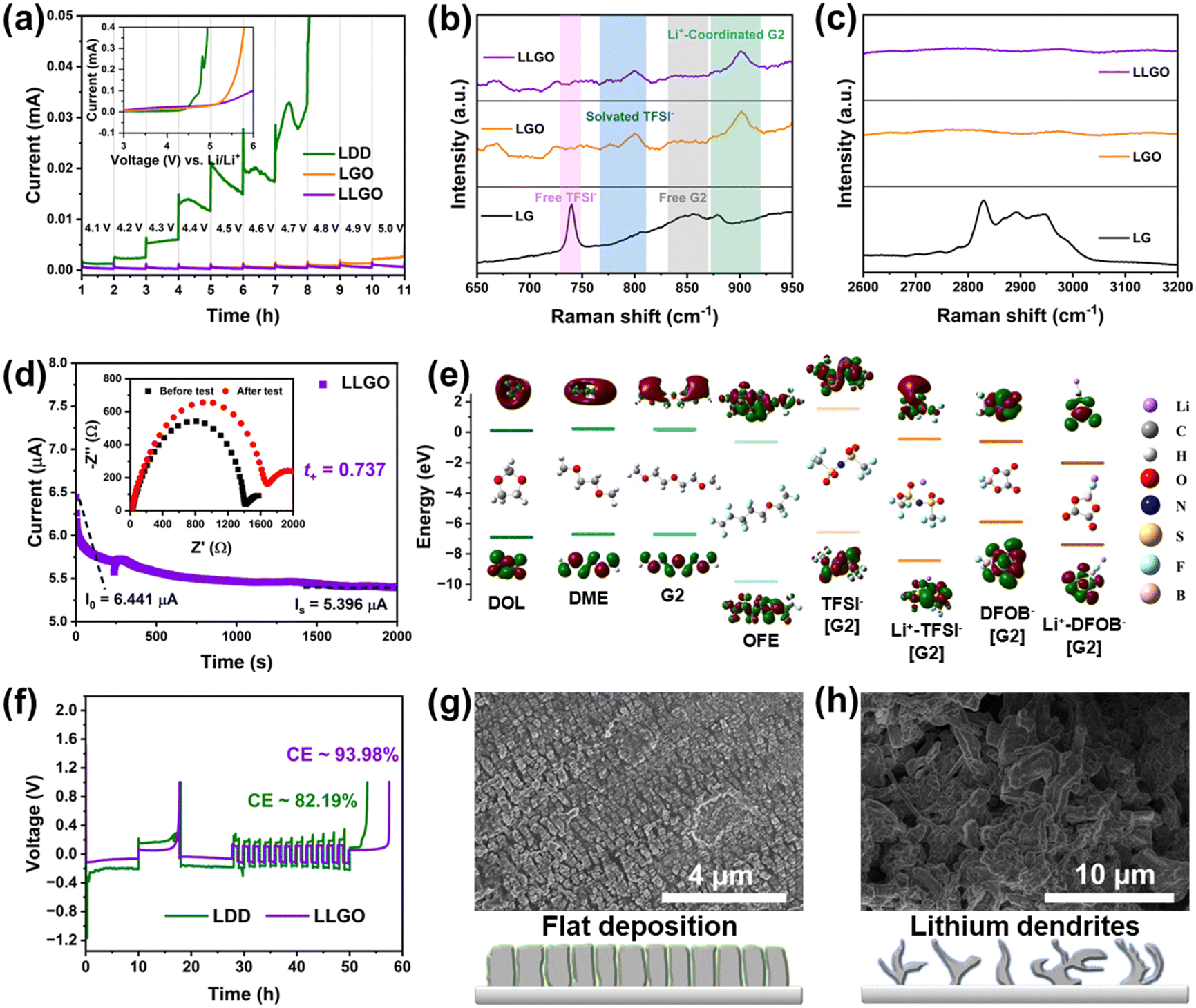 | ||
| Fig. 4 Electrochemical performance, structure and effect of different electrolyte formula. (a) Oxidation stability of different electrolytes. Inset: LSV curves of SS||electrolyte||Li cells at 1 mV s−1. Raman spectra of different electrolytes in the regions of (b) 650–950 cm−1 and (c) 2600–3200 cm−1. (d) Constant–voltage (0.01 V) polarization test of an Li||LLGO||Li cell to estimate the transference number of Li+. Inset: Electrochemical impedance spectra of the cell before and after a polarization test. (e) HOMO–LUMO energy levels for different solvent molecules, anions and Li+–anion pairs. (f) Coulombic efficiency measurement of Li||LDD/LLGO||Cu cells. SEM images of cycled Li metal anodes based on (g) LLGO and (h) LDD electrolytes. | ||
After the introduction of diluent OFE, OFE cannot solvate with Li+ ions and therefore enables the preservation of the solvation structure as in a high-concentration electrolyte system and the reduction of viscosity of the electrolyte, which can improve the transference number of Li+ from 0.56 in LDD to 0.74 in LLGO, as shown in Fig. 4(d) and Fig. S14 (ESI†). From the energy levels of the highest occupied molecular orbital (HOMO) and lowest unoccupied molecular orbital (LUMO) in Fig. 4(e), the solvent molecules of G2, OFE, DOL and DME show lower LUMO energies than that of free TFSI−. Hence, these solvent molecules aggregated in the inner Helmholtz layer at the electrode/electrolyte interface can easily participate in the construction of an SEI in LG. The interface derived from solvent molecules contains many organics and thus is loose and fragile, and the corresponding SEI cannot well protect the Li metal anode.43 In contrast, in LHCEs, the presence of the solvation structures of CIPs/AGGs reduces the LUMO energies of the anions. Consequently, the SEI derived from the salts contains more inorganic phases and is dense, and it is expected to better protect the Li anode and effectively suppress Li dendrite growth.42 On the other hand, the formation of CIPs/AGGs enables the lowering of the HOMO levels, which is favorable for the broadening of the high-voltage stabilization window of the LHCEs, agreeing with the results from SWPS and LSV. Note that both the DFOB− anion and the Li+–DFOB− pair have higher HOMO levels than the corresponding TFSI− anion and Li+–TFSI− pair. DFOB− shows the highest HOMO energy level, which indicates the preferential oxidation of DFOB− at the cathode side. Therefore the LiDFOB salt was selected as a film-forming additive for a robust CEI to suppress the dissolution of the transition metal in the cathode.
The CEs of Li/Cu cells based on diluted (LDD) and local high-concentration (LLGO) electrolytes were measured and are shown in Fig. 4(f). Obviously, the average CE value of the LLGO cell is much higher and goes up to ∼94%, and it can be ascribed to the formation of a dense SEI layer on the Li anode surface during the initial cycle in LLGO. However, the repeated rupture and growth of the SEI in the diluted electrolyte during cycling would consume Li metal and would be responsible for a low CE (∼82%). Further confirmation is demonstrated by the evolution of Li morphology during cycling in the above electrolytes (Fig. 4(g) and (h)). The anode surface is much smoother in LLGO with an ordered column Li deposition mode, and in contrast many Li dendrites appear on the Li surface in LDD, indicating a more uniform Li plating process in LHCEs and better protection effect for LHCEs on the anode.
Due to the formation of CIPs/AGGs in LHCEs, the strong interaction between cations (Li+) and anions (TFSI−/DFOB−) significantly improves the oxidation potential of the electrolyte, and is beneficial for improving the compatibility of the ether electrolyte with a high-voltage cathode. This effect is expected to activate the capacity of FeF3 in the high-voltage region (>4 V vs. Li+/Li). As shown in Fig. 5(a), when the cut-off voltage of charging is set to 4.3 V, the charge curve of the Li/FF-24 cell with LDD electrolyte shows an obvious trailing phenomenon, which does not emerge in the cell with LLGO electrolyte. This suggests the oxidative stability of solvent molecules in LLGO can effectively prevent its decomposition. Moreover, the charge curve of FeF3 in LLGO shows a distinct two-stage charge behavior corresponding to the conversion (low-voltage plateau) and intercalation (high-voltage plateau) processes, whereas the charge curve in LDD shows a conversion plateau followed by an ambiguous intercalation plateau. These comparisons indicate better structural and electrochemical reversibility of FeF3 in LLGO than in LDD. Additionally, in LLGO, the presence of a large number of anions in the inner Helmholtz layer contributes to the construction of a uniform thin CEI on the surface of the cathode after cycling, as shown in Fig. 5(b).42 According to the TEM images of discharged FF-24 in Fig. S15 (ESI†), the conversion products are uniformly distributed and wrapped into secondary particles by the CEI coating. Note that these conversion products appear in the form of nanodomains with a checkerboard-like distribution, which tightly contact with each other to form a continuous conductive network with potential interconnection of Fe0 nanoparticles (Fig. 5(b)).17 The outer CEI coating can retard the loosening and dissolution of conversion products and therefore the degradation of the built-in conductive network. The SAED pattern confirms the presence of LiF, metal Fe and a rock salt (RS) phase (e.g. Li–Fe–O–F) as well as some unconverted FeF2 after discharge (Fig. 5(c)). The corresponding HRTEM images display the characteristic lattice fringes with d-spacings of 3.33, 2.62, 2.09 and 1.48 Å, corresponding to the FeF2 (110), RS (111), RS (200)/Fe (110)/LiF (200) and RS (220)/Fe (200)/LiF (220) planes, respectively (Fig. 5(d) and Fig. S16, ESI†).44 The residual of RS and FeF2 phases is likely to be caused by the interruption of charge transfer to these nanodomains, and their existence is favorable for the stabilization of the conductive network due to a buffer effect.
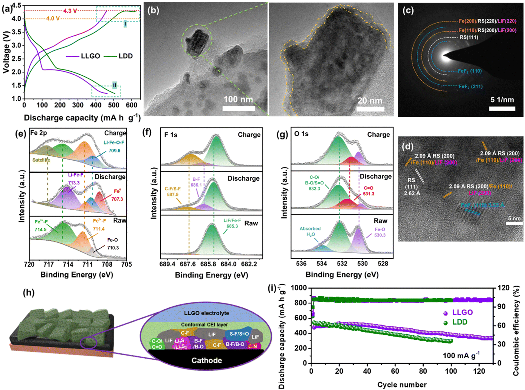 | ||
| Fig. 5 Electrochemical performance, reaction products and CEI components for FF-24 in LLGO electrolyte. (a) Electrochemical profiles and oxidation stability of FF-24 in different electrolytes and voltage ranges. (b) TEM images of discharged FF-24 electrode. The area surrounded by a yellow dashed line shows the uniform thin CEI layer on a discharged FF-24 particle. (c) SAED pattern and (d) HRTEM image of a lithiated FF-24 electrode. XPS spectra of (e) Fe 2p3/2, (f) F 1s and (g) O 1s for FF-24 electrodes before and after cycling. (h) Schematic illustration of constructed CEI components on cycled FF-24. (i) Cycling performance comparison of FF-24 cathodes in different electrolytes. | ||
The evolution of the chemical composition of the CEI layer on the surface of FF-24 cycled in LLGO electrolyte is examined by the XPS method. After discharging to 1.2 V, most Fe3+–F (at 714.5 eV) and some FeF2 (at 711.4 eV) are converted into Li–Fe–F (at 713.3 eV), Li–Fe–O–F (at 709.6 eV in the Fe 2p spectra and 530.3 eV in the O 1s spectra) and Fe0 (at 707.3 eV)/LiF (at 685.3 eV in the F 1s spectra) (Fig. 5(e)–(g)). These results are in accordance with the HRTEM and SAED results. After subsequently charging to 4 V, the Fe3+–F peak reappears and becomes pronounced and in the meantime the intensity of the Fe2+–F peak increases, along with splitting of LiF and oxidation of metallic Fe. The C![[double bond, length as m-dash]](https://www.rsc.org/images/entities/char_e001.gif) O/C–O peaks (at 531.3/532.3 eV in the O 1s spectra and at 288.8/286.5 eV in the C 1s spectra, Fig. S17, ESI†) may be associated with the decomposition of DFOB− rather than solvent molecules because of the higher HOMO energy level of DFOB− (Fig. 4(e)). The B–F and B–O bonds should be responsible for the appearance of the peaks at 686.1 eV and 523.3 eV in the F 1s (Fig. 5(f)) and O 1s (Fig. 5(g)) spectra, respectively. The signals of B-containing species (e.g. LixBOyFz) stem from the decomposition of the LiDFOB additive.45 The S–F/C–F peak at 687.5 eV, SO peak at 532.3 eV and C–N peak at 285.8 eV should stem from the decomposition of TFSI− ions rather than solvent molecules in view of the higher HOMO energy level of TFSI−. Besides, the S–F/SO signal should be responsible for the emergence of the peak at 168.4 eV in the S 2p spectra, and the peaks at 163.6 and 161.2 eV can be respectively assigned to the CS and Li2S moieties, stemming from salt decomposition (Fig. S18, ESI†). Unlike the fragile CEI layer stemming mainly from solvent decomposition in the LDD electrolyte, the CEI derived from the salts in LLGO is denser and contains LiF and B-containing species, benefitting an improvement in the stability and robustness of the CEI layer.46 This CEI effect is expected to suppress the potential side reactions between active fluoride and electrolyte as well as to impede the dissolution of Fe-based species into the electrolyte (Fig. 5(h)). Benefiting from the CEI advantage, the cycling stability of the Li/FF-24 cell based on LLGO electrolyte is significantly promoted, delivering reversible capacities as high as 500 and 335 mA h g−1 after 40 and 130 cycles at 100 mA g−1, respectively (Fig. 5(i)). The B-species in LLGO are likely to benefit the construction of solid–liquid F transport channels due to electron-deficient B attracting electron-rich F, which facilitates the dissociation of LiF.46 The activation of the ‘dead’ LiF product is responsible for the increase in discharge capacity in the early stage of cycling.
O/C–O peaks (at 531.3/532.3 eV in the O 1s spectra and at 288.8/286.5 eV in the C 1s spectra, Fig. S17, ESI†) may be associated with the decomposition of DFOB− rather than solvent molecules because of the higher HOMO energy level of DFOB− (Fig. 4(e)). The B–F and B–O bonds should be responsible for the appearance of the peaks at 686.1 eV and 523.3 eV in the F 1s (Fig. 5(f)) and O 1s (Fig. 5(g)) spectra, respectively. The signals of B-containing species (e.g. LixBOyFz) stem from the decomposition of the LiDFOB additive.45 The S–F/C–F peak at 687.5 eV, SO peak at 532.3 eV and C–N peak at 285.8 eV should stem from the decomposition of TFSI− ions rather than solvent molecules in view of the higher HOMO energy level of TFSI−. Besides, the S–F/SO signal should be responsible for the emergence of the peak at 168.4 eV in the S 2p spectra, and the peaks at 163.6 and 161.2 eV can be respectively assigned to the CS and Li2S moieties, stemming from salt decomposition (Fig. S18, ESI†). Unlike the fragile CEI layer stemming mainly from solvent decomposition in the LDD electrolyte, the CEI derived from the salts in LLGO is denser and contains LiF and B-containing species, benefitting an improvement in the stability and robustness of the CEI layer.46 This CEI effect is expected to suppress the potential side reactions between active fluoride and electrolyte as well as to impede the dissolution of Fe-based species into the electrolyte (Fig. 5(h)). Benefiting from the CEI advantage, the cycling stability of the Li/FF-24 cell based on LLGO electrolyte is significantly promoted, delivering reversible capacities as high as 500 and 335 mA h g−1 after 40 and 130 cycles at 100 mA g−1, respectively (Fig. 5(i)). The B-species in LLGO are likely to benefit the construction of solid–liquid F transport channels due to electron-deficient B attracting electron-rich F, which facilitates the dissociation of LiF.46 The activation of the ‘dead’ LiF product is responsible for the increase in discharge capacity in the early stage of cycling.
The introduced LiDFOB additive contains B, and it is a Lewis acid and may induce the ring-opening polymerization of DOL. Therefore, DOL was excluded and G2 was chosen as the final solvent for the LLGO electrolyte. We also tested the charge–discharge performance of FF-24 in 1 M LiTFSI/G2 (abbreviated as LG) electrolyte at 100 mA g−1 (Fig. S19, ESI†). Compared with LG, the LLGO electrolyte can reduce the voltage polarization, and it can be ascribed to the local high-concentration effect. Note that LLGO can effectively suppress the overcharge process and thereby improve the coulombic efficiency of the corresponding cells, and it can be ascribed to the construction of a robust CEI layer from LLGO. Therefore, LLGO imparts better electrochemical reversibility to the Li/FF-24 cell. We also increased the areal active mass loading of FF-24 to 3.45 mg cm−2, and controlled the N/P ratio to about 2.8 and the areal capacity to 2.5 mA h cm−2 (both parameters were estimated based on the theoretical capacities of FeF3 and Li). The limited contact of active species with the electrolyte and degraded electron conduction in the thick cathode lead to a sharp drop in specific capacity (Fig. S20, ESI†). Under these harsh conditions, the coulombic efficiency is still close to 100%. With optimization of the electron/ion conductive network, the capacity performance of a thick electrode can be much improved. We also chose commercial FeF3 (C–FeF3) as a control FeF3 material. The preparation method of a C–FeF3 cathode with a carbon additive and binder is similar to FF-24. Obviously, the electrochemical performance of C–FeF3 even in the optimized LLGO electrolyte is much inferior to that of FF-24 in LDD and LLGO electrolytes (Fig. S21, ESI†), strongly indicating the superiority of the synthesis method of FF-24.
Conclusions
In summary, we have proposed a dual strategy of mild C–F scissoring fluorination and local high-concentration electrolyte to enable highly reversible Li–Fe–F conversion batteries. Therein CFx serves as a solid fluorination agent to prepare iron fluorides with a micron-sized porous cubic cage-like morphology by the PCET-induced defluorination of CFx at 95 °C. The residual carbon simultaneously serves as an in situ conductive network after defluorination. The as-prepared fluoride composite enables the release of a reversible capacity of 300 mA h g−1 after 100 cycles. The LHCE strategy not only improves the oxidation stability of the electrolyte and the ability of Li+ transport by regulation of the solvation structure, but it also realizes dual protection for cathode and anode by the construction of robust CEI and SEI, respectively. Therefore, the LHCE-modified iron fluoride battery releases a higher reversible capacity of 335 mA h g−1 after 130 cycles. This work provides a solution to the green synthesis of carbon–fluoride conversion cathodes with tailored modulation of a compatible electrolyte formula.Conflicts of interest
The authors declare that they have no competing interests.Acknowledgements
This work was supported by National Natural Science Foundation of China (21975276, 52372249, 52202329), and Shanghai Science and Technology Committee (20520710800). K. Chen appreciates the support by the Shanghai Sailing Program (22YF1455400). C. Li appreciates the support by Program of Shanghai Academic Research Leader (21XD1424400).References
- C.-Y. Wang, T. Liu, X.-G. Yang, S. Ge, N. V. Stanley, E. S. Rountree, Y. Leng and B. D. McCarthy, Nature, 2022, 611, 485–490 CrossRef CAS PubMed.
- C. Li, K. Chen, X. Zhou and J. Maier, npj Comput. Mater., 2018, 4, 22 CrossRef.
- L. Wang, Z. Wu, J. Zou, P. Gao, X. Niu, H. Li and L. Chen, Joule, 2019, 3, 2086–2102 CrossRef CAS.
- K. Turcheniuk, D. Bondarev, V. Singhal and G. Yushin, Nature, 2018, 559, 467–470 CrossRef CAS PubMed.
- F. Badway, N. Pereira, F. Cosandey and G. G. Amatucci, J. Electrochem. Soc., 2003, 150, A1209–A1218 CrossRef CAS.
- C. Li, L. Gu, J. Tong and J. Maier, ACS Nano, 2011, 5, 2930–2938 CrossRef CAS PubMed.
- F. Wu, V. Srot, S. Chen, S. Lorger, P. A. van Aken, J. Maier and Y. Yu, Adv. Mater., 2019, 31, 1905146 CrossRef CAS PubMed.
- C. Li, L. Gu, S. Tsukimoto, P. A. van Aken and J. Maier, Adv. Mater., 2010, 22, 3650–3654 CrossRef CAS PubMed.
- C. Li, L. Gu, J. Tong, S. Tsukimoto and J. Maier, Adv. Funct. Mater., 2011, 21, 1391–1397 CrossRef CAS.
- C. Li, C. Yin, L. Gu, R. E. Dinnebier, X. Mu, P. A. van Aken and J. Maier, J. Am. Chem. Soc., 2013, 135, 11425–11428 CrossRef CAS PubMed.
- M. A. Reddy, B. Breitung, V. S. K. Chakravadhanula, C. Wall, M. Engel, C. Kübel, A. K. Powell, H. Hahn and M. Fichtner, Adv. Energy Mater., 2013, 3, 308–313 CrossRef CAS.
- A. R. Siedle, Y. Losovyj, J. A. Karty, D. Chen, K. Chatterjee, V. Carta, B. D. Stein and U. Werner-Zwanziger, J. Phys. Chem. C, 2021, 125, 10326–10333 CrossRef CAS.
- M. Minakawa and T. Sasaki, Synlett, 2019, 1597–1601 CAS.
- B. Sayahpour, H. Hirsh, S. Bai, N. B. Schorr, L. T. N. ambert, M. Mayer, W. Bao, D. Cheng, M. Zhang, K. Leung, K. L. Harrison, W. Li and Y. S. Meng, Adv. Energy Mater., 2022, 12, 2103196 CrossRef CAS.
- C. Li, C. Yin, X. Mu and J. Maier, Chem. Mater., 2013, 25, 962–969 CrossRef CAS.
- X. Hua, A. S. Eggeman, E. Castillo-Martinez, R. Robert, H. S. Geddes, Z. Lu, C. J. Pickard, W. Meng, K. M. Wiaderek, N. Pereira, G. G. Amatucci, P. A. Midgley, K. W. Chapman, U. Steiner, A. L. Goodwin and C. P. Grey, Nat. Mater., 2021, 20, 841–850 CrossRef CAS PubMed.
- F. Wang, R. Robert, N. A. Chernova, N. Pereira, F. Omenya, F. Badway, X. Hua, M. Ruotolo, R. Zhang, L. Wu, V. Volkov, D. Su, B. Key, M. S. Whittingham, C. P. Grey, G. G. Amatucci, Y. Zhu and J. Graetz, J. Am. Chem. Soc., 2011, 133, 18828–18836 CrossRef CAS PubMed.
- A. W. Xiao, H. J. Lee, I. Capone, A. Robertson, T.-U. Wi, J. Fawdon, S. Wheeler, H.-W. Lee, N. Grobert and M. Pasta, Nat. Mater., 2020, 19, 644–654 CrossRef CAS PubMed.
- A. P. Grosvenor, B. A. Kobe, M. C. Biesinger and N. S. McIntyre, Surf. Interface Anal., 2004, 36, 1564–1574 CrossRef CAS.
- J. H. Park, C. Park, K. S. Lee and S. J. Suh, AIP Adv., 2020, 10, 115220 CrossRef CAS.
- M. Kasrai and D. S. Urch, J. Chem. Soc., Faraday Trans. 2, 1979, 75, 1522–1531 RSC.
- I. V. Antonova, I. I. Kurkina, A. K. Gutakovskii, I. A. Kotin, A. I. Ivanov, N. A. Nebogatikova, R. A. Soots and S. A. Smagulova, Mater. Horiz., 2019, 164, 107526 CAS.
- R. G. Closser, M. Lillethorup, D. S. Bergsman and S. F. Bent, ACS Appl. Mater. Interfaces, 2019, 11, 21988–21997 CrossRef CAS PubMed.
- J. Hu, Y. Zhang, D. Cao and C. Li, J. Mater. Chem. A, 2016, 4, 16166–16174 RSC.
- K. Wang, Y. Feng, L. Kong, C. Peng, Y. Hu, W. Li, Y. Li and W. Feng, Energy Environ. Mater., 2023, 6, e12437 CrossRef CAS.
- D. A. Stevens and J. R. Dahn, J. Electrochem. Soc., 2001, 148, A803–A811 CrossRef CAS.
- H. Lindström, S. Södergren, A. Solbrand, H. Rensmo, J. Hjelm, A. Hagfeldt and S.-E. Lindquist, J. Phys. Chem. B, 1997, 101, 7717–7722 CrossRef.
- C. Lai, K. Chen, Y. Zheng, J. Meng, J. Hu and C. Li, J. Energy Chem., 2023, 78, 178–187 CrossRef CAS.
- K. Chen, W. Qiu, Q. Wu, X. Zhou, J. Liu and C. Li, J. Mater. Chem. A, 2021, 9, 6160–6171 RSC.
- A. Hess, Q. Roode-Gutzmer, C. Heubner, M. Schneider, A. Michaelis, M. Bobeth and G. Cuniberti, J. Power Sources, 2015, 299, 156–161 CrossRef CAS.
- K. Chen, Y. Zhang and C. Li, ACS Nano, 2018, 12, 12444–12455 CrossRef CAS PubMed.
- Y. Liu, J. Meng, M. Lei, Y. Yu, C. Lai and C. Li, Adv. Funct. Mater., 2023, 33, 2208013 CrossRef CAS.
- Y. S. Meng, V. Srinivasan and K. Xu, Science, 2022, 378, eabq3750 CrossRef CAS PubMed.
- H. Xue, W. He, J. Li, D. Zhang, X. Wang, S. Zhou and W. Yang, ACS Appl. Energy Mater., 2022, 5, 12553–12560 CrossRef CAS.
- X. Cao, H. Jia, W. Xu and J.-G. Zhang, J. Electrochem. Soc., 2021, 168, 010522 CrossRef CAS.
- P. Bai, X. Ji, J. Zhang, W. Zhang, S. Hou, H. Su, M. Li, T. Deng, L. Cao, S. Liu, X. He, Y. Xu and C. Wang, Angew. Chem., Int. Ed., 2022, 61, e202202731 CrossRef CAS PubMed.
- Y. Wang, Y. Zhang, S. Dong, W. Zhou, P.-K. Lee, Z. Peng, C. Dang, P. H.-L. Sit, J. Guo and D. Y. W. Yu, Adv. Energy Mater., 2022, 12, 2103360 CrossRef CAS.
- T. D. Pham, A. Bin Faheem, J. Kim, H. M. Oh and K.-K. Lee, Small, 2022, 18, 2107492 CrossRef CAS PubMed.
- K. Qian, S. Seifert, R. E. Winans and T. Li, Energy Fuels, 2021, 35, 19849–19855 CrossRef CAS.
- J. Yang, J. Ruan, Q. Li, F. Fang, Y. Song, D. Sun and F. Wang, Adv. Funct. Mater., 2022, 32, 2200566 CrossRef CAS.
- S. Prasertsri, F. Lagarde, N. Rattanasom, C. Sirisinha and P. Daniel, Polym. Test., 2013, 32, 852–861 CrossRef CAS.
- C. Tian, K. Qin and L. Suo, Mater. Futures, 2023, 2, 012101 CrossRef.
- J. Zheng, J. A. Lochala, A. Kwok, Z. D. Deng and J. Xiao, Adv. Sci., 2017, 4, 1700032 CrossRef PubMed.
- M. Sina, K. W. Nam, D. Su, N. Pereira, X. Q. Yang, G. G. Amatucci and F. Cosandey, J. Mater. Chem. A, 2013, 1, 11629–11640 RSC.
- M. Xu, L. Zhou, L. Hao, L. Xing, W. Li and B. L. Lucht, J. Power Sources, 2011, 196, 6794–6801 CrossRef CAS.
- K. Y. Chen, M. Lei, Z. G. Yao, Y. J. Zheng, J. L. Hu, C. Z. Lai and C. L. Li, Sci. Adv., 2021, 7, eabj1491 CrossRef CAS PubMed.
Footnotes |
| † Electronic supplementary information (ESI) available. See DOI: https://doi.org/10.1039/d3mh01908j |
| ‡ Y. Yu and C. Lai contributed equally to this work. |
| This journal is © The Royal Society of Chemistry 2024 |