Slippery hydrogel surface on PTFE hollow fiber membranes for sustainable emulsion separation†
Yajie
Ding
a,
Yue
Zhu
ac,
Jiawei
Wang
ac,
Jianqiang
Wang
 *ab and
Fu
Liu
 *ab
*ab
aZhejiang International Joint Laboratory of Advanced Membrane Materials & Processes, Ningbo Institute of Materials Technology & Engineering, Chinese Academy of Sciences, No. 1219 Zhongguan West Rd, Ningbo, 315201, P. R. China. E-mail: fu.liu@nimte.ac.cn; wangjianqiang@nimte.ac.cn
bUniversity of Chinese Academy of Sciences, Beijing, 100049, P. R. China
cMaterials Science and Chemical Engineering Institute, Ningbo University, Ningbo, 315211, P. R. China
First published on 19th September 2024
Abstract
Establishing an efficient and sustainable membrane module is of great significance for practical oil/water emulsion separation. Superwetting membranes have been extensively studied but cannot meet long lasting separation owing to inevitable membrane fouling. Herein, we constructed a hydrogel-mediated slippery surface on polytetrafluoroethylene (PTFE) hollow fibers and then designed a flexible and swing hollow fiber membrane module inspired by fish gill respiration, which achieved sustainable emulsion separation. A vinyl silane-crosslinked polyvinylpyrrolidone (PVP) hydrogel was interpenetrated with nano-fibrils of the PTFE hollow fibers, thus facilitating fast water permeance while resisting oil intrusion. Liquid-like polydimethylsiloxane (PDMS) brushes were then grafted to promote oil aggregation-release from the membrane surface. Owing to the heterogeneous surface and gill-like structure, the designed PTFE hollow fiber membrane module could separate emulsion in a long-term filtration process, maintaining a high water permeability of 500 L m−2 h−1 bar−1 with a separation efficiency of over 99.9% for 5000 min. This novel technique shows its great potential to realize practical emulsion separation by solving the persistent problem of membrane fouling and permeance decay.
New conceptsIn this paper, we developed a novel concept of a fish gill-inspired PTFE hollow fiber membrane module with a heterogeneous surface for sustainable emulsion separation. We constructed a heterogeneous bi-layer of a PVP hydrogel and PDMS brushes on PTFE hollow fiber membranes and then designed a flexible membrane module inspired by fish gills. The liquid-like PDMS layer is capable of capturing and releasing oil droplets from the membrane surface to alleviate membrane fouling, while that beneath the PVP hydrogel layer repels the intrusion of oil into the membrane. The hydrophilic porous fibrous structure facilitates fast and continuous water transport through the membrane freely. Furthermore, the module was designed with one fixed end and the other flexible end, thus forming swing hollow fibers. Water can be drained into the lumen side while oil droplets are captured by the PDMS layer through random oscillation, aggregation and release from the lubricant surface. Therefore, the slippery hydrogel membrane surface and the flexible hollow fiber module design allow for sustainable oil-in-water emulsion separation. |
Introduction
Oily waste generated by industry, oil spills and daily human activities pose a severe threat to ecosystems and jeopardize human health.1–3 Therefore, a viable way of eliminating oil contaminants from water is urgent. Membrane separation technology is distinguished from other traditional techniques for its highly efficient separation of emulsified oil through the physical sieving mechanism.4–7 However, unavoidable oil phase accumulation on traditional membrane surfaces leads to a severe reduction in permeability.8,9 Thus, membrane fouling is the Achilles heel hindering the practical application of membranes for oily wastewater purification.Hydration layer theory is the theoretical foundation for “antifouling” of hydrophilic membranes.10–13 Hydrophilic polymers bind tightly to water molecules via electrostatic or hydrogen bonding, forming a durable hydration layer on the membrane surface and establishing a barrier against oil adhesion. In this regard, a plethora of hydrophilic modification strategies have been devised to prevent the oil contamination on membrane surfaces.14–17 Despite the remarkable surface oil rejection capability of modified membranes, permeability still declined dramatically during the emulsion separation process.18–21 On the one hand, oil droplets tend to deform under pressure and adhere to the membrane surface, leading to the deactivation of the hydration layer. On the other hand, polar superhydrophilic groups are prone to accelerating membrane fouling in the case of electrostatic surfactant adsorption. This is attributed to the change in the wettability of the hydration layer. To overcome this obstacle, we proposed an “aggregation and demulsification” strategy to allow for the simultaneous penetration of macroscopically separated oil and water phases through the membrane, resulting in an extended purification process.22–26 However, long-lasting filtration was caused by delayed oil phase release from the membrane surface.27,28 Besides, the intrusion of oil into the membrane will occupy the spatial water channel and result in reduced water permeability.29,30
In addition, membrane module design is important for fully exploiting membrane permeability and avoiding membrane fouling, which was usually ignored by previous superwetting membranes. Gills are the respiratory organs of fish. Water enters from the mouth and exits through the gills. The direction of water flow is opposite to the direction of blood flow in the gill plates, forming a cross flow exchange system that effectively absorbs oxygen from the water flow and releases carbon dioxide into the water flow (Fig. S1, ESI†).31,32 In addition, the oscillation of the gills with the water flow facilitates the capture of oxygen from the water and reduces the adhesion of pollutants. Inspired by this, we may design a flexible hollow fiber module that can facilitate the water permeance and suppress oil fouling via fiber swing and aggregation-releasing mechanism on the fiber surface.
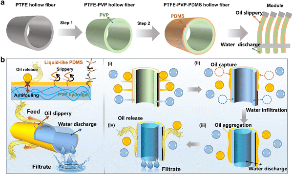
Herein, a heterogeneous hydrogel/slippery surface-modified hollow fiber membrane (PTFE–PVP–PDMS) was fabricated by the construction of an ultrathin hydrophobic liquid-like PDMS layer and PVP hydrogel interlayer on PTFE hollow fiber membrane successively. The hollow fibers were assembled into a flexible outside-in filtration module, in which one end of the hollow fiber was fixed and worked as an exit port, while the other end is sealed and swings in the feed solution freely (Fig. S2, ESI†). Under the cross flow and membrane filament oscillation, the hydrophilic inner layer of the hollow fiber membrane was able to absorb the water phase from the emulsion and discharge purified water, while the liquid-like PDMS layer on the outer wall agglomerated the oil phase and released it back to the emulsion. The synergy of cross flow shear and membrane filament oscillation drives the dynamic antifouling efficiently. It is emphasized that the hydrogel-mediated antifouling strategy provides a new approach to repair membrane fouling for durable oil–water separation.
Results and discussion
Design and construction of hydrogel-mediated slippery membrane
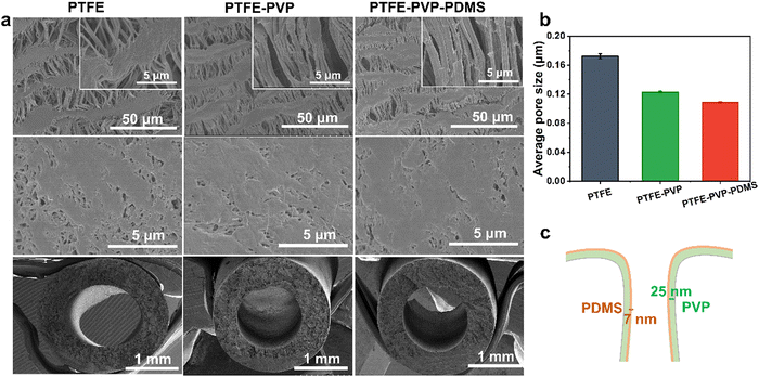
The hydrogel-mediated slippery antifouling membrane was constructed, as demonstrated in Fig. 1a. PTFE hollow fiber membrane was first modified by crosslinking the PVP–VTES hydrogel network to establish the hydrophilic channel. The hydrophobic PDMS layer was subsequently grafted to form an oil receptor and slippery surface. This is due to the extremely low glass transition temperature (Tg: 127 °C) of PDMS, which has rotational dynamic properties at room temperature and acts as a liquid lubrication layer that both reduces fouling and promotes the sliding of the liquid on the membrane–liquid interface.33,34 Heterogeneous hollow fiber membranes were then assembled into a fish gill-like membrane module by fixing the single-end. As described in Fig. 1b, when separating oil-in-water emulsions under cross flow conditions in an outside-in operation, the liquid-like PDMS brushes are expected to first capture and aggregate the oil droplets driven to the membrane surface. The aggregated oil phase is then easily released from the feed solution by the cross-flow shear, membrane filament oscillation, and slippery effect of the lubricant PDMS layer. The strong hydration of the PVP-crosslinked hydrogel layer under the PDMS layer aids the membrane in resisting further oil intrusion. The Laplace force promoted continuous water phase penetration into the thin PDMS layer beneath the porous structure, which was collected in the inner lumen of the hollow fiber membrane and discharged as purified water.The heterogeneous bi-layer of the PTFE–PVP–PDMS hollow fiber membrane was constructed by a two-step modification. As shown in Fig. S3 (ESI†), the hydrophilic monomers NVP were copolymerized with VTES via a free radical reaction to form a precursor, which was then mixed into a PTFE hollow fiber membrane. After hydrolysis with 2% citric acid, a crosslinked hydrogel network was formed on the PTFE membrane to obtain a PTFE–PVP membrane.35 Subsequently, the resultant membrane was further reacted with DMS by polycondensation to form the PTFE–PVP–PDMS hollow fiber.36 The SEM images show the morphology and microstructure of the inner, outer surfaces and cross sections of the hollow fiber membranes. As depicted in Fig. 2a, the inner surface of the pristine PTFE hollow fiber membrane is composed of “protofibril” and the “node”, the outer surface is smooth with unevenly distributed small holes, and the membrane as a whole has a spongy structure. The surface morphology of the modified membrane (PTFE–PVP and PTFE–PVP–PDMS membrane) was similar to that of the as-prepared membrane. No obvious pore clogging was observed, indicating that the modification would not negatively affect the pore channels of the membranes. Fig. 2b and Fig. S4 (ESI†) show that the pore sizes of the PTFE–PVP and PTFE–PVP–PDMS membranes are similar but smaller than those of PTFE membranes, which suggests that PVP and PDMS are effectively attached to the membrane pore surfaces to shrink the effective pore size of the membrane. It could be estimated that the thickness of the PVP hydrogel layer is about 25 nm, and the thickness of the slippery PDMS layer is about 7 nm (Fig. 2c).
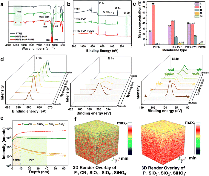
The surface chemistry was further analyzed by FTIR and XPS throughout the synthesis process. As illustrated in Fig. 3a, the absorption peaks at 1728, 1631, and 1658 cm−1 (C![[double bond, length as m-dash]](https://www.rsc.org/images/entities/char_e001.gif) O) were ascribed to the PVP skeleton.37 The emerging peaks at 3365 cm−1 belong to Si–OH and those at 912 cm−1 and 1145 cm−1 are ascribed to Si–O–Si, both of which gradually increased from PTFE–PVP to PTFE–PVP–PDMS, indicating the chemical crosslinking sites for PVP and DMS.38 The XPS pattern further revealed that the new O, N and Si peaks appeared in the PTFE–PVP and PTFE–PVP–PDMS membrane (Fig. 3b). The successful loading of the PVP-crosslinked hydrogel is indicated by the corresponding percentage of elemental content, e.g., a decrease in F and an increase in O, N, and Si, as compared to the pristine PTFE membrane. The successful grafting of PDMS was further confirmed by a decrease in the percentage of F and N and a significant increase in the percentage of O and Si in the XPS spectra (Fig. 3c). The modification was further verified by XPS depth profiling (Fig. 3d and Fig. S5, ESI†). With the gradual increase in the depth, the F element on the outer surface of the PTFE–PVP–PDMS membrane gradually increased to a constant value, which indicates that the modified layer is covered on the PTFE membrane's outer surface. However, the N (O) element first increases and then decreases to a constant value, and the decrease in the Si element from a high to a constant value proves that slippery PDMS is present in the outer wall of the PTFE–PVP–PDMS membrane and the PVP-crosslinked hydrogel wraps around the entire PTFE membrane. In addition, as shown in Fig. S6 (ESI†), the TGA curve for the pristine PTFE membrane showed that the sample remained stable up to about 500 °C, followed by a single stage of total decomposition. From the TGA curve for the PTFE–PVP membrane, there are two regions of degradation, namely, at 160–210 °C and 480–610 °C, due to the structural degradation of the PVP–VTES and PTFE substrate. After the further modification of PDMS, the TGA curve of PDMS shows an initial mass loss at 210 °C due to the decomposition of low molecular weight species.39 Similar to PTFE, it undergoes single-stage thermal decomposition, which means that the PDMS layer has been successfully modified and can effectively protect the PVP–VTES layer.
O) were ascribed to the PVP skeleton.37 The emerging peaks at 3365 cm−1 belong to Si–OH and those at 912 cm−1 and 1145 cm−1 are ascribed to Si–O–Si, both of which gradually increased from PTFE–PVP to PTFE–PVP–PDMS, indicating the chemical crosslinking sites for PVP and DMS.38 The XPS pattern further revealed that the new O, N and Si peaks appeared in the PTFE–PVP and PTFE–PVP–PDMS membrane (Fig. 3b). The successful loading of the PVP-crosslinked hydrogel is indicated by the corresponding percentage of elemental content, e.g., a decrease in F and an increase in O, N, and Si, as compared to the pristine PTFE membrane. The successful grafting of PDMS was further confirmed by a decrease in the percentage of F and N and a significant increase in the percentage of O and Si in the XPS spectra (Fig. 3c). The modification was further verified by XPS depth profiling (Fig. 3d and Fig. S5, ESI†). With the gradual increase in the depth, the F element on the outer surface of the PTFE–PVP–PDMS membrane gradually increased to a constant value, which indicates that the modified layer is covered on the PTFE membrane's outer surface. However, the N (O) element first increases and then decreases to a constant value, and the decrease in the Si element from a high to a constant value proves that slippery PDMS is present in the outer wall of the PTFE–PVP–PDMS membrane and the PVP-crosslinked hydrogel wraps around the entire PTFE membrane. In addition, as shown in Fig. S6 (ESI†), the TGA curve for the pristine PTFE membrane showed that the sample remained stable up to about 500 °C, followed by a single stage of total decomposition. From the TGA curve for the PTFE–PVP membrane, there are two regions of degradation, namely, at 160–210 °C and 480–610 °C, due to the structural degradation of the PVP–VTES and PTFE substrate. After the further modification of PDMS, the TGA curve of PDMS shows an initial mass loss at 210 °C due to the decomposition of low molecular weight species.39 Similar to PTFE, it undergoes single-stage thermal decomposition, which means that the PDMS layer has been successfully modified and can effectively protect the PVP–VTES layer.
The hierarchical surface spatial structure of the PTFE–PVP–PDMS membrane was further validated by time-of-flight secondary ion mass spectrometry (TOF-SIMS). The sputtered secondary negative ions were collected by layer-by-layer bombardment and etching of the outermost surface of the membrane by a primary ion beam, and the spatial elemental distributions were analyzed in a 300 μm × 300 μm area. Based on the theoretical molecular structure, F− and CN− were identified as secondary negative ions representing the PTFE matrix and PVP, respectively. SiO3−, SiO2− and SiHO3− were represented as PVP and PDMS. As shown in the dynamic negative ion-depth profile in Fig. 3e, throughout the etching process, the intensities of F− and CN− gradually increased and stabilized. On the other hand, the intensity of the SiO3−, SiO2− and SiHO3− increases and then gradually decreases. It fully proves that the crosslinked PVP hydrogel successfully wrapped the PTFE matrix and PDMS grafted on the outer wall of the hollow fiber membrane. The thickness of the PVP layer is about 27–30 nm and the thickness of the PDMS layer is about 6–9 nm, which is consistent with the pore size variation analysis in Fig. 2c. The hydrophilic modification of the internal channels of the membrane will greatly facilitate the transport of continuous water phases. The hydrophobic modification of the outer wall surface of the membrane will greatly contribute to the demulsification, aggregation, and release of dispersed oil phases. For a more intuitive display, Fig. 3f shows the reconstructed 3D image of the depth profiles with five/four representative negatives marked with ions in different colors. In addition to the results obtained above, it is easy to find that the PVP is evenly covered on the PTFE substrate and PDMS exists on the upper surface of the membrane. Thus, it lays a great foundation for the construction of the antifouling membrane.
Oil capture-aggregation-release for hydrogel-mediated slippery membrane
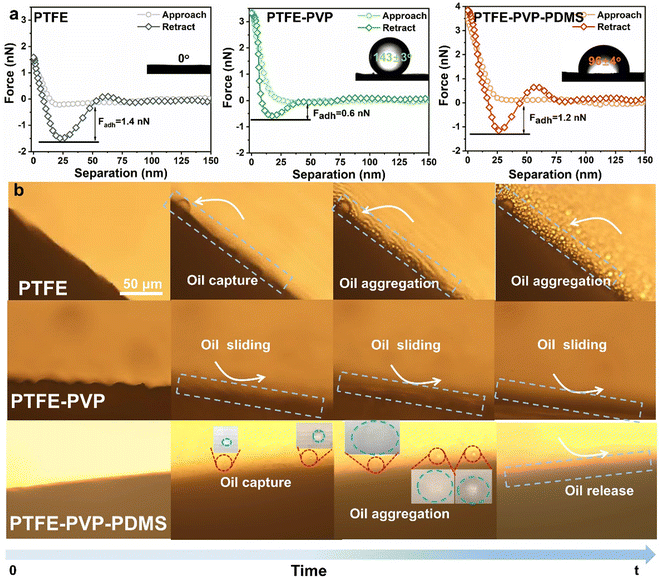
The wettability and oil adhesion properties of the membranes were characterized. As shown in Fig. S7 and S8 (ESI†), the water contact angle (WCA) and underwater oil contact angle (UOCA) of the pristine PTFE were inner surface: 127° ± 3°, outer surface: 129° ± 2° and 0°, respectively, indicating its inherent hydrophobicity. After winding the PVP–VTES crosslinked hydrogel, the WCA of the PTFE–PVP membrane was quickly decreased to 0° within 0.43 s as the water droplet spread over time, which indicates superior wettability. The UOCA of the inner and outer surfaces shifts to 140° ± 2° and 143° ± 3°, respectively. High oleophobicity underwater helps to defend the membrane surface against oil intrusion. After decorating the hydrophobic PDMS layer on the outer surface of the hydrophilic PTFE–PVP membrane, a Janus structure was formed,40 and the diffusion time of the water droplets on the outer surface was extended to 3.82 s, while the inner layer remained almost unchanged. The UOCA of the inner and outer surfaces changed to 135° ± 1° and 96° ± 4°, respectively, indicating that the moderate oleophobicity of the membrane outer surface was favorable for oil droplet capture and aggregation.To demonstrate this, further underwater dynamic oil adhesion and CA measurements were performed to assess the oil droplet capture capability of the membrane. As shown in Fig. S9a, c and Videos S1, S2 (ESI†), when an oil droplet is forced into full contact with the PTFE and PTFE–PVP–PDMS membrane's outer surface and then lifted underwater, the oil droplet is easily captured by the membrane surface. In contrast, despite the repeated squeezing of the oil droplets against the membrane surface, the oil droplets were not significantly deformed and difficult to deposit on the PTFE–PVP membrane (Fig. S9b and Video S3, ESI†). The oil capture capacity of the membranes was evaluated by AFM. The adhesion forces between different membranes towards oil were found to be in the following order: PTFE (1.4 nN) > PTFE–PVP–PDMS (1.2 nN) > PTFE–PVP (0.6 nN) (Fig. 4a). As a result, it is not difficult to hypothesize that the PTFE–PVP–PDMS membrane surface would efficiently capture the oil droplets and accelerate emulsion demulsification in a real cross-flow filtration condition.
To avoid the accumulation of an oil cake layer, oil droplets are required to be released as soon as they come into contact with the membrane surface. Under cross-flow, oil droplets deposited on the membrane surface are usually sheared by the continuous feed solution. Therefore, to simplify the model, the oil-in-water emulsion was allowed to contact the surface of the membrane, and the movement behavior of the oil droplets was observed under an optical microscope. As shown in Fig. 4b and Video S4 (ESI†), dispersed oil droplets were captured on the surface of the PTFE membrane and aggregated to form large oil droplets, but no detachment was observed. The reason for this is the strong affinity of the PTFE membrane for oil droplets.41 The movement of oil droplets in the emulsion on the PTFE membrane is depicted in Fig. S10a (ESI†), where oil droplets accumulate and adhere to the membrane surface. Instead of adhering to the membrane, oil droplets quickly bounced away and slid from the PTFE–PVP membrane surface due to the strong hydration capacity of the membrane (Fig. 4b and Fig. S10b, Video S5, ESI†).42 Unexpectedly, for the PTFE–PVP–PDMS membranes, oil droplets undergo capture, aggregation, and release on the membrane surface (Fig. 4b and Fig. S10c, Video S6, ESI†). The outstanding performance implies that the liquid-like PDMS layer effectively captures oil droplets and releases the agglomerated oil phase.43–45 As a result, the PTFE–PVP–PDMS membrane is expected to realize a continuous oil–water separation process.
Separation performance of the hydrogel-mediated slippery antifouling membrane
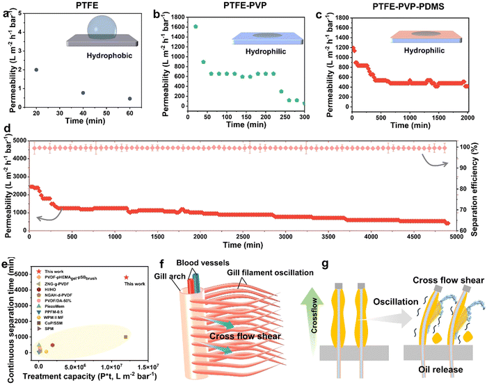
The goal of “hydrogel/slippery heterogeneous surface” design is to give membranes with a gill-like structure to promote the oil-phase aggregation, release and avoid water permeability degradation during the oil/water separation process. Therefore, we evaluated the continuous dynamic separation performance of membranes by a homemade cross-flow device at a pressure of 10 kPa (Fig. S11, ESI†). It is shown that the permeation ability of the pristine PTFE membrane was nearly zero due to its hydrophobicity (Fig. 5a).46 In contrast, with merely PVP coverage, the PTFE-PVP membrane provides the effective separation of oil–water emulsions with a high permeability of 1600 L m−2 h−1 bar−1. It is owing to the superhydrophilic interface of the PVP hydrogel-crosslinked network (Fig. 5b). However, as the separation proceeded, the permeability rapidly dropped to 0 within 300 min. On grafting PDMS on the outer wall of the PTFE–PVP hollow fiber membrane, named as PTFE–PVP–PDMS membrane, it was found that the permeability remained almost constant after first decreasing to 500 L m−2 h−1 bar−1. The entire separation process lasted more than 2000 min (Fig. 5c). The decrease in the flux may be due to the fact that the PDMS brushes were not completely covered with PTFE–PVP membranes.42 After separation, the oil-in-water emulsion changed from milky white to clear, and the emulsified oil droplets with particle size between 0.8 μm and 10 μm were removed (Fig. S12, ESI†). The oil retention rate is over 99.9%, which is due to the fact that the hydrophobic slippery PDMS layer facilitates the capture and aggregation of small oil droplets in the emulsion to demulsification (Fig. S13, ESI†). The oil recovery is calculated by collecting the floating oil on the liquid after separation, which is about 60% (Fig. S14, ESI†). When the membranes were cleaned with ethanol, the permeability recovery rate (FRR) reached more than 99% (Fig. S15, ESI†). Besides, the PTFE–PVP–PDMS membranes can continuously stabilize the separation of hexadecane-in-water emulsions for over 5000 min and realize the continuous and stable separation of water-in-isooctane emulsion for 1200 min, which is a few to several hundred times higher than that in previous literature (Fig. 5d and Fig. S16, S17, ESI†).5,14,15,42,47–52 The corresponding emulsion handling capacity is 1–350 times higher than that reported in other works (Fig. 5e). The difference in the permeability may be due to the differences in the viscosity and interfacial tension. Since the modified layers designed in this work have a well-defined spatial structure, the reason for the different separation properties of the three membranes was deduced, as shown in Fig. 5f and g. Under cross-flow, the oil–water PTFE–PVP–PDMS membrane allows the continuous water phase of the emulsion to enter the inner lumen of the membrane through the Laplace force, while the oil phase is captured on the outer surface of the membrane to be demulsified, agglomerated, and released from the feed solution through the synergistic action of liquid-like PDMS, water shear, and fish gill-like membrane filament oscillation.40,53–55 The length of the membrane filament is optimally oscillated at 10 cm, which facilitates the release of the aggregated oil phase from the surface of the membrane filament (Fig. S18, ESI†). The rapid release of the agglomerated oil phase from the hydrophobic liquid-like PDMS prevents the oil droplets from forming a thick cake layer. Hydrophilic PVP hydrogel-mediated slippery membrane prevents the aggregated oil phase from entering the interior of the membrane. As a result, water is able to pass through, which imparts a constant permeability to the membrane (Fig. S19a, ESI†). However, if there is no hydrophobic layer (slippery layer) on the membrane surface, the oil droplets will quickly bounce off the membrane surface, thus keeping the permeability high for a certain period of time (Fig. S19b, ESI†). However, due to the superhydrophilicity of PVP, the emulsified oil droplets are more likely to aggregate in the solution and form a dense oil film, which adheres to the membrane surface. The oil film penetrates into the PTFE oil-absorbing layer under the Laplace force, causing irreversible fouling and a decrease in the membrane permeability. On the other hand, on the PTFE membrane without any modification, the affinity of oil droplets to the membrane triggers irreversible oil diffusion and an oil layer that prevents the water phase from passing through the membrane (no hydrophilic layer). Thus, PTFE membranes have low permeability (Fig. S19c, ESI†).The molecular chain length of the grafted PDMS may affect the specific properties of the membrane. The synergistic function of the heterogeneous wettability layer was thus evaluated by adjusting the chain length of the PDMS with the PVP fixed. From Fig. S20 (ESI†), when the modification time of PDMS is shortened or lengthened, the permeability decreases rapidly within 300 min. The results show that the hydrogel-mediated slippery membrane can fully utilize its superior anti-fouling performance only when PVP and PDMS reach an optimal balance. Therefore, the optimal duration of the polycondensation reaction was 15 min, and the PTFE–PVP–PDMS membrane was prepared for all characterization and performance testing throughout the work. In summary, hydrogel-mediated slippery antifouling enabled the membrane to maintain long-lasting and efficient oil-in-water emulsion separation performance.
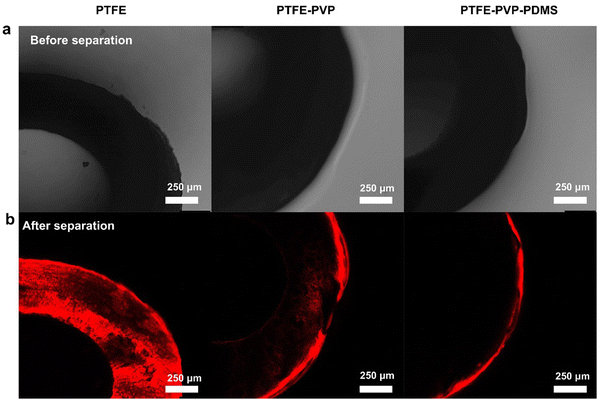
To further verify the hydrogel-mediated slippery antifouling ability for oil-in-water emulsion, the movement and distribution of oil droplets on the membrane surface was detected using LSCM. The simultaneous observation of the state of stained emulsions and the color of hydrophilic and hydrophobic layers of the membranes by laser emission was combined with bright-field observation. With the aid of fluorescent staining, the distribution of the oil droplets on the membrane surface after separation could be recognized by the luminescent areas. It is worth noting that the fluorescence of Nile Red has an excitation wavelength of 488 nm and an emission wavelength of 540–700 nm. As shown in Fig. 6, due to the hydrophobicity of PTFE, the whole PTFE hollow fiber membrane shows a red color. For the PTFE–PVP membrane, the oil-phase droplets enter the hydrated layer and make the membrane locally reddened, while only the PDMS layer of the PTFE–PVP–PDMS membrane is reddened. These results also indicate the superiority of the hydrogel-mediated slippery antifouling PTFE–PVP–PDMS membrane for continuous antifouling separation.
Conclusions
We proposed a heterogeneous surface on PTFE hollow fiber consisting of a PVP hydrogel layer and a PDMS slippery layer. The bi-layer of hydrophilic and lipophilic components plays a key role in realizing the dynamic antifouling of the oil/water separation. Based on the well-designed “hydrogel-mediated slippery” barrier established by the spatial molecular structure of fouling “aggregation-release”, the outer surface of the membrane effectively aggregates the oil phase and releases it back into the emulsion, while the hydrophilic inner wall absorbs the water phase from the emulsion into the lumen to generate purified water. When separating various oil-in-water emulsions under cross-flow, the permeability of the membrane could still be maintained above 500 L m−2 h−1 bar−1 for 5000 min of continuous separation. We envision that the concept of the slippery hydrogel membrane holds promise for antifouling membranes for the long-term purification of practical oily wastewater.Experimental section
Please refer to the ESI† for details on membrane fabrication, device characterization and testing.Author contributions
Yajie Ding: conceptualization, methodology, investigation, writing – original draft preparation. Yue Zhu: visualization, investigation. Jiawei Wang: visualization, investigation. Jianqiang Wang: writing – review & editing, supervision. Fu Liu: conceptualization, writing – review & editing, supervision. All authors contributed to the discussion and interpretation of the results.Data availability
The data supporting this article have been included as part of the ESI.†Conflicts of interest
There are no conflicts to declare.Acknowledgements
This work is financially supported by National Natural Science Foundation of China (Grant No. 22205248, 52373111), China Postdoctoral Science Foundation, China (2022M713240), Natural Science Foundation of Ningbo, China (2022J303), Ningbo International R&D Collaboration Project, China (2023H001), the International Partnership Program of Chinese Academy of Sciences-Grand Challenges, China (No. 181GJHZ2022038GC), the National Natural Science Foundation of China (51973230), Zhejiang Provincial Natural Science Foundation of China for Distinguished Young Scholars, China (LR20E030002).Notes and references
- Y. Dong, Y. Liu, C. Hu, I. R. MacDonald and Y. Lu, Science, 2022, 376, 1300–1304 CrossRef CAS PubMed.
- I. Leifer, Science, 2022, 376, 1266 CrossRef CAS PubMed.
- M. Rodrigues, Nature, 2023, 619, 680–681 CrossRef CAS PubMed.
- T. Huang, Z. Su, K. Hou, J. Zeng, H. Zhou, L. Zhang and S. P. Nunes, Chem. Soc. Rev., 2023, 52, 4173–4207 RSC.
- Y. Zhao, Y. Gu, B. Liu, Y. Yan, C. Shan, J. Guo, S. Zhang, C. D. Vecitis and G. Gao, Nature, 2022, 608, 69–73 CrossRef CAS PubMed.
- F. Tian, Y. Yang, X. Wang, W. An, X. Zhao, S. Xu and Y. Wang, Mater. Horiz., 2019, 6, 1733–1739 RSC.
- C. Li, B. Lee, C. Wang, A. Bajpayee, L. D. Douglas, B. K. Phillips, G. Yu, N. Rivera-Gonzalez, B. J. Peng, Z. Jiang, H. J. Sue, S. Banerjee and L. Fang, Mater. Horiz., 2022, 9, 452–461 RSC.
- M. Obaid, H. O. Mohamed, A. S. Yasin, M. A. Yassin, O. A. Fadali, H. Kim and N. A. M. Barakat, Water Res., 2017, 123, 524–535 CrossRef CAS PubMed.
- Z. Zhu, W. Wang, D. Qi, Y. Luo, Y. Liu, Y. Xu, F. Cui, C. Wang and X. Chen, Adv. Mater., 2018, 30, 1801870 CrossRef PubMed.
- B. Xiang, Q. Sun, Q. Zhong, P. Mu and J. Li, J. Mater. Chem. A, 2022, 10, 20190–20217 RSC.
- Q. Ma, H. Cheng, A. G. Fane, R. Wang and H. Zhang, Small, 2016, 12, 2186–2202 CrossRef CAS PubMed.
- X. Yan, X. Xiao, C. Au, S. Mathur, L. Huang, Y. Wang, Z. Zhang, Z. Zhu, M. J. Kipper, J. Tang and J. Chen, J. Mater. Chem. A, 2021, 9, 21659–21684 RSC.
- J. Zhang, F. Zhang, J. Song, L. Liu, Y. Si, J. Yu and B. Ding, J. Mater. Chem. A, 2019, 7, 20075–20102 RSC.
- Y. Zhu, J. Wang, F. Zhang, S. Gao, A. Wang, W. Fang and J. Jin, Adv. Funct. Mater., 2018, 28, 1804121 CrossRef.
- S. Gao, J. Chen, Y. Zheng, A. Wang, D. Dong, Y. Zhu, Y. Zhang, W. Fang and J. Jin, Adv. Funct. Mater., 2022, 32, 2205990 CrossRef CAS.
- Z. Bai, K. Jia, S. Zhang, G. Lin, Y. Huang and X. Liu, Adv. Funct. Mater., 2022, 32, 2204612 CrossRef CAS.
- A. Borbora, R. L. Dupont, Y. Xu, X. Wang and U. Manna, Mater. Horiz., 2022, 9, 991–1001 RSC.
- E. Tummons, Q. Han, H. J. Tanudjaja, C. A. Hejase, J. W. Chew and V. V. Tarabara, Sep. Purif. Technol., 2020, 248, 116919 CrossRef CAS.
- P. D. Sutrisna, K. A. Kurnia, U. W. R. Siagian, S. Ismadji and I. G. Wenten, J. Environ. Chem. Eng., 2022, 10, 107532 CrossRef CAS.
- J. Zhang, K. Peng, Z. K. Xu, Y. Xiong, J. Liu, C. Cai and X. Huang, Adv. Colloid Interface Sci., 2023, 319, 102971 CrossRef CAS PubMed.
- S. Huang, R. H. A. Ras and X. Tian, Curr. Opin. Colloid Interface Sci., 2018, 36, 90–109 CrossRef CAS.
- M. Hlavacek, J. Membr. Sci., 1995, 102, 1–7 CrossRef CAS.
- X. Zhu, L. Zhu, H. Li, C. Zhang, J. Xue, R. Wang, X. Qiao and Q. Xue, J. Membr. Sci., 2021, 630, 119324 CrossRef CAS.
- J. Wang, B. He, Y. Ding, T. Li, W. Zhang, Y. Zhang, F. Liu and C. Y. Tang, ACS Appl. Mater. Interfaces, 2021, 13, 4731–4739 CrossRef CAS PubMed.
- P. Shi, R. Zhang, W. Pu, R. Liu and S. Fang, J. Cleaner Prod., 2022, 330, 129945 CrossRef CAS.
- D. Sun, X. Duan, W. Li and D. Zhou, J. Membr. Sci., 1998, 146, 65–72 CrossRef CAS.
- Y. Ding, B. Hu, L. Zhuang, J. Wang, J. Wu, F. Liu and J. Wang, ACS Appl. Mater. Interfaces, 2021, 13, 30224–30234 CrossRef CAS PubMed.
- Y. Ding, N. Qiu, J. Wang, Z. Yang, F. Liu and C. Y. Tang, J. Membr. Sci., 2023, 684, 121820 CrossRef CAS.
- Y. Ding, J. Wang, J. Wu, J. Wang and F. Liu, J. Membr. Sci., 2023, 673, 121484 CrossRef CAS.
- Y. Zhu, Y. Ding, J. Wang, H. Lin, F. Liu and C. Y. Tang, Sep. Purif. Technol., 2024, 343, 126934 CrossRef CAS.
- Y. Dou, D. Tian, Z. Sun, Q. Liu, N. Zhang, J. H. Kim, L. Jiang and S. X. Dou, ACS Nano, 2017, 11, 2477–2485 CrossRef CAS PubMed.
- S. L. Sanderson, A. Y. Cheer, J. S. Goodrich, J. D. Graziano and W. T. Callan, Nature, 2001, 412, 439–441 CrossRef CAS PubMed.
- L. Chen, Q. Feng, S. Huang, Z. Lin, J. Li and X. Tian, J. Membr. Sci., 2020, 610, 118240 CrossRef CAS.
- I. J. Gresham and C. Neto, Adv. Colloid Interface Sci., 2023, 315, 102906 CrossRef CAS PubMed.
- W. Liu, H. Lin, J. Wang, Q. Han and F. Liu, J. Membr. Sci., 2021, 630, 119301 CrossRef CAS.
- L. Chen, S. Huang, R. H. A. Ras and X. Tian, Nat. Rev. Chem., 2023, 7, 123–137 CrossRef CAS PubMed.
- T. Li, F. Liu, H. Lin, Z. Xiong, H. Wang, Y. Zhong, L. Xiang and A. Wu, J. Colloid Interface Sci., 2018, 517, 93–103 CrossRef CAS PubMed.
- Y. Wang, H. Lin, Z. Xiong, Z. Wu, Y. Wang, L. Xiang, A. Wu and F. Liu, J. Membr. Sci., 2016, 520, 769–778 CrossRef CAS.
- T. Eder, A. Mautner, Y. Xu, M. R. Reithofer, A. Bismarck and J. M. Chin, ACS Appl. Mater. Interfaces, 2024, 16, 10942–10952 CrossRef CAS PubMed.
- H. C. Yang, J. Hou, V. Chen and Z. K. Xu, Angew. Chem., Int. Ed., 2016, 55, 13398–13407 CrossRef CAS PubMed.
- J. Chai, G. Wang, A. Zhang, X. Li, Z. Xu, J. Zhao and G. Zhao, Chem. Eng. J., 2023, 461, 141971 CrossRef CAS.
- D. Dong, Y. Zhu, W. Fang, M. Ji, A. Wang, S. Gao, H. Lin, R. Huang and J. Jin, Adv. Funct. Mater., 2022, 32, 2113247 CrossRef CAS.
- Y. Liu, X. Wang and S. Feng, Adv. Funct. Mater., 2019, 29, 1902488 CrossRef.
- Z. Wang, M. Lehtinen and G. Liu, Angew. Chem., Int. Ed., 2017, 56, 12892–12897 CrossRef CAS PubMed.
- R. Zang, Y. Wang, J. Meng, W. Chen, B. Wang, X. Xu, X. He, H. Yang, K. Li and S. Wang, Mater. Horiz., 2022, 9, 2872–2880 RSC.
- B. Zhang, S. Yu, Y. Zhu, Y. Shen, X. Gao, W. Shi and J. Hwa Tay, Sep. Purif. Technol., 2020, 235, 116212 CrossRef CAS.
- Y. Zhao, X. Yang, Z. Cheng, C. H. Lau, J. Ma and L. Shao, Nat. Commun., 2023, 14, 2679 CrossRef CAS PubMed.
- X. Cheng, Y. Ye, Z. Li, X. Chen, Q. Bai, K. Wang, Y. Zhang, E. Drioli and J. Ma, ACS Nano, 2022, 16, 4684–4692 CrossRef CAS PubMed.
- Z. Li, Y. Liu, X. Wei, Z. Zhang, F. Zhao, T. Wang, Y. Du, E. Shi, C. Fan, Y. Yang and Z. Jiang, Adv. Funct. Mater., 2024, 2405915 CrossRef.
- Y. Wang, S. Yang, J. Zhang, Z. Chen, B. Zhu, J. Li, S. Liang, Y. Bai, J. Xu, D. Rao, L. Dong, C. Zhang and X. Yang, Nat. Commun., 2023, 14, 1108 CrossRef CAS PubMed.
- H. Li, J. Zhang, S. Gan, X. Liu, L. Zhu, F. Xia, X. Luo and Q. Xue, Adv. Funct. Mater., 2023, 33, 2212582 CrossRef CAS.
- Y. Yan, P. Zhou, Y. Zhou, W. Zhang, P. Pi, Y. Qian, X. Wen and L. Jiang, J. Am. Chem. Soc., 2024, 146, 13306–13316 CrossRef CAS PubMed.
- Z. Wang, G. Liu and S. Huang, Angew. Chem., Int. Ed., 2016, 55, 14610–14613 CrossRef CAS PubMed.
- H. Li, J. Yang and Z. Xu, J. Membr. Sci., 2020, 602, 117964 CrossRef.
- Y. Qi, C. Zhou, Y. Qiu, X. Cao, W. Niu, S. Wu, Y. Zheng, W. Ma, H. Ye and S. Zhang, Mater. Horiz., 2022, 9, 1243–1252 RSC.
Footnote |
| † Electronic supplementary information (ESI) available. See DOI: https://doi.org/10.1039/d4mh00946k |
| This journal is © The Royal Society of Chemistry 2024 |

