 Open Access Article
Overcoming copper-induced conversion reactions in nickel disulphide anodes for sodium-ion batteries†
Milan K.
Sadan
 *ab,
Taehong
Kim
b,
Anupriya K.
Haridas
 c,
Hooam
Yu
b,
Denis
Cumming
 d,
Jou-Hyeon
Ahn
 b and
Hyo-Jun
Ahn
 *b
*b
aDyson School of Design Engineering, Imperial College London, Imperial College Rd, South Kensington, London SW7 2DB, UK. E-mail: m.kooplikkattil-sadan@imperial.ac.uk
bDepartment of Materials Engineering and Convergence Technology, Gyeongsang National University, Jinju 52828, Republic of Korea
cEnergy Innovation Centre, Warwick Manufacturing Group, University of Warwick, Coventry, CV4 7AL, UK
dDepartment of Chemical and Biological Engineering, University of Sheffield, Mappin Street, Sheffield S1 3JD, UK
First published on 16th April 2024
Abstract
Employing copper (Cu) as an anode current collector for metal sulphides is perceived as a general strategy to achieve stable cycle performance in sodium-ion batteries, despite the compatibility of the aluminium current collector with sodium at low voltages. The capacity retention is attributed to the formation of copper sulphide with the slow corrosion of the current collector during cycling which is not ideal. Conventional reports on metal sulphides demonstrate excellent electrochemical performances using excessive carbon coatings/additives, reducing the overall energy density of the cells and making it difficult to understand the underlying side reaction with Cu. In this report, the negative influence of the Cu current collector is demonstrated with in-house synthesised, scalable NiS2 nanoparticles without any carbon coating as opposed to previous works on NiS2 anodes. Ex situ TEM and XPS experiments revealed the formation of Cu2S, further to which various current collectors were employed for NiS2 anode to rule out the parasitic reaction and to understand the true performance of the material. Overall, this study proposes the utilisation of carbon-coated aluminium foil (C/Al) as a suitable current collector for high active material content NiS2 anodes and metal sulphides in general with minimal carbon contents as it remains completely inert during the cycling process. Using a C/Al current collector, the NiS2 anode exhibits stable cycling performance for 5000 cycles at 50 A g−1, maintaining a capacity of 238 mA h g−1 with a capacity decay rate of 8.47 × 10⁻³% per cycle.
1. Introduction
Currently, lithium-ion batteries (LIBs) are among the leading options in energy storage devices. However, the overexploitation of lithium and its limited availability could lead to a lithium shortage in the near future.1 Sodium-ion batteries (SIBs) emerge as viable alternatives to LIBs, owing to their similar electrochemical properties.2–5 Additionally, sodium is both evenly distributed globally and economically accessible. Various candidates for SIB cathodes have been explored using technologies commonly applied to LIBs, and their performance has been significantly enhanced.6–10 Nevertheless, the performance of anode materials based on carbonaceous materials has been found to be unsatisfactory.11,12 Numerous studies have centred on developing new anode materials that interact with sodium through alloying13,14 or phase conversion.15–17 Specifically, metal sulphide (MyS) converts to metal (M) and sodium sulphide (Na2S) through sodiation, as shown in eqn (1).| MyS + 2 Na ⇌ yM + Na2S | (1) |
In this report, we prepared NiS2 powder without any specialised carbon nanostructure. NiS2 was synthesised by heating a mixture of nickel and sulphur powders, following a simple and scalable process. The NiS2 electrode was fabricated using a conventional method, specifically slurry casting onto current collectors. The effects of different electrolytes and current collectors on the cycling properties were investigated. If a copper current collector were involved in side reactions during the electrochemical process, the possibility of exploring replacing it is studied further. The degradation mechanism was also discussed based on the results. The NiS2 electrode exhibited remarkable performance when paired with a copper current collector, an outcome related to the formation of Cu2S. Carbon-coated aluminium foil emerged as a suitable substitute for the current collector, showing no side reactions. Using a carbon-coated aluminium (C/Al) current collector, the NiS2 electrode demonstrated excellent rate performance up to 100 A g−1. Moreover, stable cycling performance was observed for up to 5000 cycles at a current density of 50 A g−1, maintaining a capacity retention of 71%.
2. Experimental
2.1. Synthesis of NiS2
Nickel sulphide was synthesised by mixing nickel and sulphur powders, followed by heating at 500 °C for 3 h in an argon atmosphere. Nickel nanopowder (99%, Nanotechnology, Korea) and sulphur micron powder (Aldrich) were used as precursors. The nickel and sulphur powders were mixed in a molar ratio of 1![[thin space (1/6-em)]](https://www.rsc.org/images/entities/char_2009.gif) :
:![[thin space (1/6-em)]](https://www.rsc.org/images/entities/char_2009.gif) 8 for 10 h using a planetary ball mill (Pulverisette 6, Fritsch GmbH, Germany) and dried in an oven at 60 °C for 8 h. The dried powder was then annealed in a tube furnace at 500 °C for 3 h with a ramp rate of 5 °C min−1, in an argon atmosphere.
8 for 10 h using a planetary ball mill (Pulverisette 6, Fritsch GmbH, Germany) and dried in an oven at 60 °C for 8 h. The dried powder was then annealed in a tube furnace at 500 °C for 3 h with a ramp rate of 5 °C min−1, in an argon atmosphere.
2.2. Structural characterisation
The crystal structure was analysed using an X-ray Diffractometer (Bruker D2 Phaser, USA). To determine sulphide formation, Raman spectra were obtained using a LabRAM HR800 UV. Morphological evolution was assessed with a field-emission scanning electron microscope (FESEM Quanta3D, FEI, Netherlands). Further details of the crystal structure were elucidated using TEM (FEI, TF30ST). Ex situ X-ray photoelectron spectroscopy (XPS; PHI 5000 VersaProbe, Ulvac-PHI, Inc., Kanagawa, Japan) was conducted with the aid of glovebox to minimise exposure.2.3. Electrochemical characterisation
The NiS2 electrode was prepared with 80% NiS2, 10% Ketjen Black (AkzoNobel, EC-600JD), and 10% PVDF (Sigma Aldrich). These components were thoroughly mixed using N-methyl-2-pyrrolidone (Sigma Aldrich) and coated onto various current collectors, including copper foil (Wellcos), aluminium foil (Wellcos), carbon-coated aluminium foil (MTI Korea), carbon nanotube-coated aluminium foil (Prime 1E, Gratube Co.), nickel foil (Alfa Aesar Co.), stainless steel foil (Alfa Aesar Co.), and titanium foil (Alfa Aesar Co.). The coated slurry was dried in a vacuum oven at 80 °C for 12 h. The mass of the active material was ∼1 mg cm−2. Swagelok-type cells were assembled for electrochemical testing. Sodium metal was employed as both a counter electrode and a reference electrode, while glass fibre (Whatman, GF/D) and Celgard served as separators. The cells were tested at room temperature within a voltage window of 0.01 to 3 V (WBCS 3000L, WonA Tech Co., South Korea) using either ether-based or carbonate-based electrolytes. A 1 M solution of sodium hexafluorophosphate (NaPF6, Alfa Aesar, 99+% purity) dissolved in 1,2-dimethoxyethane (DME, Sigma Aldrich) was used as the ether electrolyte. For comparison, a 1 M NaPF6 solution in ethylene carbonate (EC)/diethylene carbonate (DEC) with 5 wt% fluoroethylene carbonate (FEC) was utilised as the carbonate electrolyte. Impedance spectra were measured in the frequency range from 1 to 0.01 MHz using a VMP3 multi-channel potentiostat (Biologic, Seyssinet-Pariset, France). Cyclic voltammetry was performed at a voltage scan rate of 0.1 mV s−1 within the 0.01 to 3 V voltage window. A four-probe analysis was conducted using a portable 4-probe resistivity tester (MTI, EQ-JX2008-LD). The galvanostatic intermittent titration technique (GITT) was carried out at a current density of 500 mA g−1, with a 10 minute rest time between charge and discharge cycles.3. Results and discussion
The nickel disulphide (NiS2) was synthesised by mixing spherical nickel nanoparticles with sulphur, followed by a simple heat treatment at 500 °C for 3 h in an argon atmosphere. This method provides a facile and scalable process for synthesising NiS2. Fig. 1a displays the XRD pattern of the synthesised particles, which consist of a single phase of NiS2 with a cubic pyrite structure (JCPDS # 89-7142).24,25,33 Additionally, the Raman spectrum in Fig. 1b confirms the pure NiS2 phase, exhibiting a doublet at around 280 cm−1 and a sharp peak at 480 cm−1. The peak at 272 cm−1 is attributed to Tg phonon vibration, and the peak at 280 cm−1 is assigned to Eg phonon vibration. The sharp peak at 480 cm−1 corresponds to Ag phonon vibration in NiS2.34,35Fig. 1c shows the FESEM image of NiS2, which features spherical particles clustered together. This morphology is further investigated using TEM, as shown in Fig. 1d. The spherical shape of the NiS2 nanoparticles resembles that of the Ni precursor, as seen in Fig. S1a.† Given that the annealing temperature was 500 °C, sulphur vapour (with a boiling point of 444 °C) could react with the spherical nickel particles to form spherical NiS2 particles. The HRTEM image in Fig. 1e reveals lattice spacings of 0.23 nm and 0.28 nm, which correspond to the (211) and (200) planes of cubic NiS2, respectively.20,26,29,36 This HRTEM result further corroborates the formation of NiS2, aligning with the XRD pattern. From the STEM image and EDS mapping in Fig. S2,† nickel and sulphur are uniformly distributed throughout the NiS2 particles.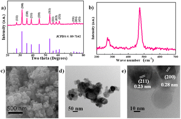 | ||
| Fig. 1 (a) XRD, (b) Raman spectra, (c) SEM, (d) TEM, and (e) HRTEM of nickel disulphide, respectively. | ||
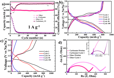
NiS2 electrodes were prepared on a copper current collector and cycled using two types of electrolytes. The cycling performance of the NiS2 electrode in ether-based (DME) and carbonate-based (EC/DEC) electrolytes is shown in Fig. 2. The cycling properties are largely dependent on the type of electrolyte, as illustrated in Fig. 2a. In the case of DME electrolyte, the initial discharge capacity is 856 mA h g−1 with a high coulombic efficiency of 94%, and it remains at 804 mA h g−1 after 100 cycles. Conversely, in the case of the EC/DEC electrolyte, the capacity of the NiS2 electrode drastically decreases within 20 cycles and stays below 30 mA h g−1. The variations in voltage profile are represented in Fig. 2b and c. In the DME electrolyte, two plateaus appear at 1.3 V and 1.0 V during the first discharge (sodiation), and two more plateaus appear at 1.6 V and 1.9 V during the first charge curve. Although the capacity remains relatively stable during cycling, the plateau potentials in the discharge curve significantly change with repeated cycling; a short plateau appears around 2.0 V at the 10th cycle, followed by a long plateau at 1.5 V after the 50th cycle. These variations in plateau potential likely indicate changes in the sodiation reaction. In the EC/DEC electrolyte, as seen in Fig. 2c, the initial discharge curve is similar to that of the DME electrolyte. However, the capacity drastically decreases, and the discharge curve exhibits a sloping behaviour without a flat plateau after the 10th cycle. To investigate the differences between the two electrolytes, the electrochemical impedance spectroscopy (EIS) of the NiS2 electrode in both DME and EC/DEC has been analysed and is displayed in Fig. 2d. In the DME electrolyte, the charge transfer resistance (Rct) of the pristine NiS2 electrode is approximately 40 Ω and decreases to ∼10 Ω after the first cycle. For the EC/DEC electrolyte, the initial Rct value is ∼400 Ω, which is substantially higher than that of the DME electrolyte. Moreover, the Rct value for the carbonate-based electrolyte increases after the first cycle.
It has been reported that the high Rct in carbonate electrolytes is associated with a thick solid electrolyte interphase (SEI) layer.37 This thick SEI layer could lead to electrical isolation between NiS2 particles, resulting in parasitic reactions that consume alkali ions in subsequent cycles.38–41 Such phenomena could be linked to poor cycling behaviour. On the other hand, ether-based electrolytes are reported to form a thin SEI layer on the active material.42–44 Although the NiS2 electrode was prepared without any specialised carbon nanostructure, its cycling performance was excellent when using a Cu current collector and DME electrolyte. The electrochemical properties under these conditions have been investigated in detail.
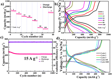
From Fig. 3, the NiS2 electrode exhibited excellent rate performance when using a DME electrolyte and a copper current collector, delivering a reversible capacity of ∼800 mA h g−1 at 1 A g−1 and 132 mA h g−1 at a high current density of 100 A g−1. The voltage profile at various current densities in the DME electrolyte is illustrated in Fig. 3b. In Fig. 3c, stable cycling performance is observed at a high current density of 15 A g−1 over 1000 cycles. The capacity decreases during the initial stage but stabilises after 200 cycles. The variation in the voltage profile during cycling is displayed in Fig. 3d. A single plateau at 1.5 V during discharge appears after the 100th cycle, exhibiting the same behaviour as in Fig. 2b.
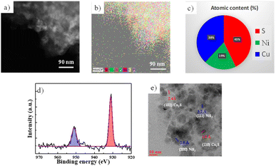
In Fig. 4, the NiS2 electrode using DME electrolyte and a Cu current collector was investigated after 1000 cycles in the charged state. Fig. 4a and b displays TEM images and EDS mapping results from TEM, indicating the presence of both copper and nickel. Fig. 4c presents the atomic concentrations in the 1000th cycled electrode based on X-ray photoelectron spectroscopy (XPS) data. After 1000 cycles, elements of copper, nickel, and sulphur were detected. The copper elements likely originate from the Cu current collector, which is the only source of copper in the cell. In Fig. 4d, XPS results of the 1000-cycle sample show two peaks at 931 eV and 951 eV, corresponding to the Cu 2p3/2 and Cu 2p1/2 of copper sulphide (Cu2S), respectively.32,45 The HRTEM image in Fig. 4e reveals lattice spacings of 0.28 nm and 0.32 nm, corresponding to the (200) and (111) planes of NiS2, respectively. However, the lattice spacing of 0.19 nm could not be explained by NiS2 but is well-matched with the (110) planes of Cu2S. Thus, a Cu2S phase appeared in the NiS2 electrode after 1000 cycles.
From the above results, it can be concluded that Cu2S was formed during the cycling of the NiS2 electrode for sodium-ion batteries. These findings are consistent with previous studies that used ether and a Cu current collector.30–32 Additionally, the single plateau at 1.5 V after cycling in Fig. 2d aligns with the plateau of Cu2S.46–48 Initially, the capacity should arise from the sodiation of sulphur, which is a reversible reaction involving Na2S and transition metals (Ni or Cu).27,49–51 After cycling, some of the sulphur in NiS2 likely transformed into Cu2S via a reaction with copper. However, since the total amount of sulphur in both Cu2S and NiS2 should remain equal to that of pristine NiS2, the capacity did not decrease; instead, a flat plateau at 1.5 V appeared after cycling. This plateau is characteristic of Cu2S.28 Thus, the plateau at 1.5 V likely originates from Cu2S. The capacity after cycling was derived from both NiS2 and Cu2S, and the total amount of sulphur should be the same as that in pristine NiS2. This phenomenon may be associated with the good cycling properties observed.
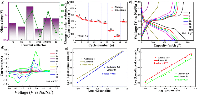
Even though copper foil is considered as a candidate for an anode current collector, it reacts with NiS2 to form Cu2S. To identify the appropriate current collector for a NiS2 electrode, various popular current collectors were investigated, including aluminium foil, carbon nanotube-coated aluminium foil (CNT/Al), carbon-coated aluminium foil (C/Al), stainless steel foil, titanium foil, and nickel foil. The ohmic drop (at ∼1.7 V) in the galvanostatic intermittent titration technique (GITT) is shown in Fig. S3† and summarised in Fig. 5a. Data from electrochemical impedance spectroscopy, including charge transfer resistance derived from the Nyquist plot, are also integrated into Fig. 5a. The NiS2 electrode using a C/Al (carbon-coated aluminium foil) current collector exhibited the lowest charge transfer resistance, potentially promoting faster kinetics. Fig. 5b displays the rate performance of the NiS2 electrode using a C/Al current collector and DME electrolyte. The NiS2 electrode delivered high capacities of 738, 642, 605, 583, 546, and 293 mA h g−1 at current densities of 1, 2, 5, 10, 20, and 50 A g−1, respectively. Moreover, at an extremely high current density of 100 A g−1, the electrode delivered a capacity of 129 mA h g−1. This performance is similar to that observed with a Cu current collector in Fig. 3a and exceeds the rate performance reported in previous studies on NiS2.19,20,22,25,26,50,52–56 The high-rate performance of the NiS2 electrode is likely an intrinsic property. Fig. 5c presents the voltage profile at various rates. For kinetic analysis, cyclic voltammetry was performed at different current densities ranging from 0.1 to 20 mV s−1 (shown in Fig. 5d). During both anodic and cathodic scans, two peaks were observed in both the reduction and oxidation processes. Fig. 5e and f show the linear relationship between anodic/cathodic peak current and scan rate, consistent with eqn (2).57,58
| i = aVb | (2) |
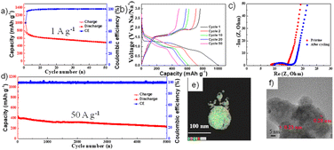
Fig. 6 illustrates the cycling properties of the NiS2 electrode using a C/Al current collector. The short-term cycling performance was conducted at a current rate of 1 A g−1 (Fig. 6a), and the corresponding voltage profile is displayed in Fig. 6b. The first discharge curve exhibits two plateaus, similar to that observed when using a Cu current collector in Fig. 2b. However, a flat plateau does not appear during cycling, differing from the behaviour observed with a Cu current collector in Fig. 2b. In other words, there may be no side reactions. According to Fig. S4† (EDS mapping results of the cycled electrode), the aluminium element was not detected in the NiS2 electrode after cycling. The C/Al foil should be inert during cycling and thus stands as a good candidate for the NiS2 electrode in sodium-ion batteries. The Nyquist plot of the pristine NiS2 electrode and the electrode after cycling is presented in Fig. 6c. The Rct was approximately 14 Ω initially and increased slightly to 16 Ω after cycling. The low charge transfer resistance could suggest fast kinetics. The long-term cycling performance was conducted at a current density of 50 A g−1, as shown in Fig. 6d, with the corresponding voltage profile presented in Fig. S5.† The NiS2 electrode exhibited an initial capacity of 413 mA h g−1 and a capacity decay rate of 8.47 × 10⁻³% per cycle over 5000 cycles. The discharge curve shows a sloping behaviour but lacks any plateau at 1.5 V. EDS mapping results obtained through TEM are displayed in Fig. 6e. After 5000 cycles, nickel and sulphur were observed, but aluminium was not detected in the NiS2 electrode. High-resolution TEM (HRTEM) images after 5000 cycles are shown in Fig. 6f. The d-spacing corresponds to 0.28 nm and 0.23 nm, which relate to the (200) and (211) planes of NiS2, respectively.
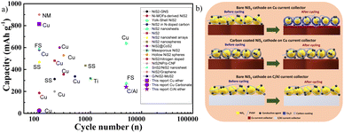
Table S1† presents previous reports on NiS2 electrodes. Fig. 7a displays the cycling performance of these previous studies, along with cell conditions such as electrode structure, electrolyte, and current collector. Specifically, the current collectors, electrolytes, and electrodes are systematically represented. Copper, stainless steel, titanium, and carbon-coated aluminium have been used as current collectors. Carbonate-based electrolytes such as EC, DMC, DEC, PC, FEC, as well as ether-based electrolytes like DME and DEGDME, have been employed for various types of NiS2 electrodes. When using carbonate electrolytes, some previous reports showed poor cycling properties for NiS2 electrodes prepared without carbon coatings.13,28 Despite this, most NiS2 electrodes featuring carbon nanostructures exhibited good cycling properties when paired with carbonate electrolytes. Additionally, NiS2 electrodes using ether electrolytes and copper current collectors displayed a 1.5 V plateau after cycling.28 When NiS2 electrodes were cycled with ether electrolytes and alternative current collectors like stainless steel and Ti, the clear 1.5 V plateau during discharge was not observed.19,20,22,60 Based on our results and previous findings, the expected reaction mechanism responsible for metal sulphide behaviour is summarised in Fig. 7b. This reaction can be applied to all metal disulphide anodes, irrespective of the electrolyte used. In the case of ether electrolytes, bare NiS2 could react with copper foil to form copper sulphide during cycling, thereby promoting stable cycling.45,61,62 The formation of copper sulphide could be identified by the appearance of a plateau at 1.5 V during discharge. Moreover, bare NiS2 electrodes displayed poor cycling properties, potentially related to the formation of a thick SEI layer. Copper foil may not be an ideal current collector for bare nickel disulphides. However, there are two approaches to overcome the side reactions of copper current collectors. The first involves modifying the NiS2 electrode with a thick, uniform carbon coating, which can also be compatible with carbonate electrolytes. A thick carbon coating on nickel sulphide acts as a barrier, preventing the direct contact of copper and thereby mitigating side reactions. The main drawback of this strategy is reduced volumetric capacity. The alternative solution is to change the current collector; for example, carbon-coated aluminium foil can be used with a bare NiS2 electrode in an ether-type electrolyte. This strategy can also be applied to other metal sulphide anode materials to explore their real capacities without side reactions. This superior electrochemical performance highlights the promising practical applications of NiS2 anodes for sodium-ion batteries. Additionally, this strategy can be adapted to other metal sulphides to mitigate the side reactions involving copper current collectors.
Conclusions
Nickel disulphide (NiS2) was prepared using a facile and scalable method without any carbon coating and employed as anode material for sodium-ion batteries using a Cu current collector and a DME-based electrolyte. The NiS2 anode paired with the Cu current collector exhibited long cycle life and rapid kinetics. However, it was found that the copper current collector triggered a side reaction, leading to the formation of copper sulphide. As alternative strategies, various current collectors like nickel foil, stainless steel foil, titanium foil, aluminium foil, carbon-coated aluminium foil (C/Al) and CNT-coated aluminium foil were considered. Among these, the C/Al collector was found to be the best alternative due to its inert nature and low resistivity. The electrode with C/Al displayed high-rate performance and long-term cycling stability. Even at a high current rate of 100 A g−1, the capacity remained at 129 mA h g−1. Additionally, the electrode exhibited excellent rate performance at a current density of 50 A g−1; at the end of 5000 cycles, the capacity was maintained at 238 mA h g−1. This report outlines a new direction for conversion anode research in sodium-ion batteries by putting forward an alternative current collector with low resistivity and inertness to metal sulphides.Conflicts of interest
There are no conflicts to declare.Acknowledgements
This research was supported by the National Research Foundation of Korea (NRF), funded by the Ministry of Science, ICT, and Future Planning (MSIP) [Grant numbers: RS-2023-00208635] and the Korea Institute for Advancement of Technology (KIAT), funded by the Ministry of Trade, Industry, and Energy (MOTIE, Korea) [Grant number: 20016346]Notes and references
- M. Fichtner, Batteries Supercaps, 2021, 5, e202100224 CrossRef.
- N. Tapia-Ruiz, A. R. Armstrong, H. Alptekin, M. A. Amores, H. Au, J. Barker, R. Boston, W. R. Brant, J. M. Brittain, Y. Chen, M. Chhowalla, Y.-S. Choi, S. I. R. Costa, M. Crespo Ribadeneyra, S. A. Cussen, E. J. Cussen, W. I. F. David, A. V. Desai, S. A. M. Dickson, E. I. Eweka, J. D. Forero-Saboya, C. P. Grey, J. M. Griffin, P. Gross, X. Hua, J. T. S. Irvine, P. Johansson, M. O. Jones, M. Karlsmo, E. Kendrick, E. Kim, O. V. Kolosov, Z. Li, S. F. L. Mertens, R. Mogensen, L. Monconduit, R. E. Morris, A. J. Naylor, S. Nikman, C. A. O'Keefe, D. M. C. Ould, R. G. Palgrave, P. Poizot, A. Ponrouch, S. Renault, E. M. Reynolds, A. Rudola, R. Sayers, D. O. Scanlon, S. Sen, V. R. Seymour, B. Silván, M. T. Sougrati, L. Stievano, G. S. Stone, C. I. Thomas, M.-M. Titirici, J. Tong, T. J. Wood, D. S. Wright and R. Younesi, J. Phys.: Energy, 2021, 3, 031503 CAS.
- Z. Guo, G. Qian, C. Wang, G. Zhang, R. Yin, W.-D. Liu, R. Liu and Y. Chen, Prog. Nat. Sci.: Mater. Int., 2023, 1, 1–7, DOI:10.1016/j.pnsc.2022.12.003.
- I. Mohan, A. Raj, K. Shubham, D. B. Lata, S. Mandal and S. Kumar, J. Energy Storage, 2022, 55, 105625 CrossRef.
- Y. Wu, X. Meng, L. Yan, Q. Kang, H. Du, C. Wan, M. Fan and T. Ma, J. Mater. Chem. A, 2022, 10, 21816–21837 RSC.
- C. Hakim, N. Sabi and I. Saadoune, J. Energy Chem., 2021, 61, 47–60 CrossRef CAS.
- J. Peng, W. Zhang, Q. Liu, J. Wang, S. Chou, H. Liu and S. Dou, Adv. Mater., 2022, 34, e2108384 CrossRef PubMed.
- T. Song and E. Kendrick, J. Phys.: Mater., 2021, 4, 032004 CAS.
- M. K. Sadan, A. K. Haridas, H. Kim, C. Kim, G. B. Cho, K. K. Cho, J. H. Ahn and H. J. Ahn, Nanoscale Adv., 2020, 2, 5166–5170 RSC.
- A. K. Haridas, M. K. Sadan, J.-H. Kim, Y. Lee and J.-H. Ahn, Batteries, 2022, 8, 237 CrossRef CAS.
- L. Fang, N. Bahlawane, W. Sun, H. Pan, B. B. Xu, M. Yan and Y. Jiang, Small, 2021, 17, e2101137 CrossRef PubMed.
- Z. G. Liu, R. Du, X. X. He, J. C. Wang, Y. Qiao, L. Li and S. L. Chou, ChemSusChem, 2021, 14, 3724–3743 CrossRef CAS PubMed.
- C. Kim, H. Kim, M. K. Sadan, M. Jeon, G. Cho, J. Ahn, K. Kim, K. Cho and H. Ahn, Small, 2021, 17, e2102618 CrossRef PubMed.
- M. W. Orzech, F. Mazzali, J. D. McGettrick, C. Pleydell-Pearce, T. M. Watson, W. Voice, D. Jarvis and S. Margadonna, J. Mater. Chem. A, 2017, 5, 23198–23208 RSC.
- A. K. Haridas, M. K. Sadan, H. Kim, J. Heo, S. Sik Kim, C. H. Choi, H. Young Jung, H. J. Ahn and J. H. Ahn, ChemSusChem, 2021, 14, 1936–1947 CrossRef CAS PubMed.
- A. K. Haridas, M. K. Sadan, Y. Liu, H. Y. Jung, Y. Lee, H.-J. Ahn and J.-H. Ahn, J. Alloys Compd., 2022, 928, 167125 CrossRef CAS.
- A. K. Haridas, N. Angulakshmi, A. M. Stephan, Y. Lee and J. H. Ahn, Molecules, 2021, 26, 4349 CrossRef CAS PubMed.
- Y. Wu, C. Zhang, H. Zhao and Y. Lei, J. Mater. Chem. A, 2021, 9, 9506–9534 RSC.
- R. Sun, S. Liu, Q. Wei, J. Sheng, S. Zhu, Q. An and L. Mai, Small, 2017, 13, 1701744 CrossRef PubMed.
- Q. Chen, S. Sun, T. Zhai, M. Yang, X. Zhao and H. Xia, Adv. Energy Mater., 2018, 8, 1800054 CrossRef.
- W. X. Zhang, J. H. Zhang, J. Q. Guo, C. He and J. R. Wen, J. Alloys Compd., 2023, 937, 168379 CrossRef CAS.
- M.-P. Fan, Y.-C. Chen, Y.-M. Chen, Z.-X. Huang, W.-L. Wu, P. Wang, X. Ke, S.-H. Sun and Z.-C. Shi, Rare Met., 2022, 41, 1294–1303 CrossRef CAS.
- J. Zhao, G. Wang, K. Cheng, K. Ye, K. Zhu, J. Yan, D. Cao and H.-E. Wang, J. Power Sources, 2020, 451, 227737 CrossRef CAS.
- W. Zhao, S. Ci, X. Hu, J. Chen and Z. Wen, Nanoscale, 2019, 11, 4688–4695 RSC.
- M. K. Sadan, H. H. Kim, C. Kim, G. B. Cho, N. S. Reddy, K. K. Cho, T. H. Nam, K. W. Kim, J. H. Ahn and H. J. Ahn, J. Nanosci. Nanotechnol., 2020, 20, 7119–7123 CrossRef CAS PubMed.
- R. Bi, C. Zeng, H. Huang, X. Wang and L. Zhang, J. Mater. Chem. A, 2018, 6, 14077–14082 RSC.
- W. Li, B. Huang, Z. Liu, J. Yang, Y. Li, S. Xiao, Q. Chen, G. Li, X. Zhao and W. Zhang, Electrochim. Acta, 2021, 369, 137704 CrossRef CAS.
- J. Cai, X. Chen, X. Duan, G. Yang, Q. Zhang, H. Fan, Z. Liu and F. Peng, Electrochim. Acta, 2023, 462, 142705 CrossRef CAS.
- G. Zhao, Y. Zhang, L. Yang, Y. Jiang, Y. Zhang, W. Hong, Y. Tian, H. Zhao, J. Hu, L. Zhou, H. Hou, X. Ji and L. Mai, Adv. Funct. Mater., 2018, 28, 1803690 CrossRef.
- Q. Li, Q. Wei, Q. An, L. Huang, W. Luo, X. Ren, K. A. Owusu, F. Dong, L. Li, P. Zhou, L. Mai, Q. Zhang, K. Amine and J. Lu, Energy Storage Mater., 2019, 16, 625–631 CrossRef.
- W. Yang, K. Wang, W. Zhou, N. Luo, S. Huang, Y. Li, K. N. Hui and M. Wei, J. Mater. Chem. A, 2022, 10, 25575–25585 RSC.
- G. Zu, G. Guo, H. Li, Y. Lu, R. Wang, Y. Hu, L. Wang and J. Wang, J. Mater. Chem. A, 2020, 8, 6569–6575 RSC.
- R. Karthikeyan, D. Thangaraju, N. Prakash and Y. Hayakawa, CrystEngComm, 2015, 17, 5431–5439 RSC.
- T. Suzuki, K. Uchinokura, T. Sekine and E. Matsuura, Solid State Commun., 1977, 23, 847–852 CrossRef CAS.
- K. Han, J. Meng, X. Hong, X. Wang and L. Mai, Nanoscale, 2020, 12, 8255–8261 RSC.
- K. J. Zhu, G. Liu, Y. J. Wang, J. Liu, S. T. Li, L. Y. Yang, S. L. Liu, H. Wang and T. Xie, Mater. Lett., 2017, 197, 180–183 CrossRef CAS.
- M. Zhou, H. Tao, K. Wang, S. Cheng and K. Jiang, J. Mater. Chem. A, 2018, 6, 24425–24432 RSC.
- Z. W. Seh, J. Sun, Y. Sun and Y. Cui, ACS Cent. Sci., 2015, 1, 449–455 CrossRef CAS PubMed.
- Y. Huang, L. Zhao, L. Li, M. Xie, F. Wu and R. Chen, Adv. Mater., 2019, 31, e1808393 CrossRef PubMed.
- L. Lutz, D. Alves Dalla Corte, M. Tang, E. Salager, M. Deschamps, A. Grimaud, L. Johnson, P. G. Bruce and J.-M. Tarascon, Chem. Mater., 2017, 29, 6066–6075 CrossRef CAS.
- A. Ponrouch, D. Monti, A. Boschin, B. Steen, P. Johansson and M. R. Palacín, J. Mater. Chem. A, 2015, 3, 22–42 RSC.
- L. Yan, G. Zhang, J. Wang, Q. Ren, L. Fan, B. Liu, Y. Wang, W. Lei, D. Ruan, Q. Zhang and Z. Shi, Energy Environ. Mater., 2022, 6, e12523 CrossRef.
- J. Zhu, X. Qiao and T. Chen, Ionics, 2022, 28, 2267–2276 CrossRef CAS.
- Y. Wang, P. Bai, B. Li, C. Zhao, Z. Chen, M. Li, H. Su, J. Yang and Y. Xu, Adv. Energy Mater., 2021, 11, 2101972 CrossRef CAS.
- C. Zhou, S. Wan, Y. Chen, L. Fu, H. Chen, C. Kang and Q. Liu, J. Power Sources, 2021, 509, 230401 CrossRef CAS.
- Y. Hu, L. Zhang, J. Bai, F. Liu, Z. Wang, W. Wu, R. Bradley, L. Li, H. Ruan and S. Guo, ACS Appl. Energy Mater., 2021, 4, 8901–8909 CrossRef CAS.
- X. Liu, X. Li, X. Lu, X. He, N. Jiang, Y. Huo, C. Xu and D. Lin, J. Alloys Compd., 2021, 854, 157132 CrossRef CAS.
- Zulkifli, S. Lee, G. Alfaza, A. N. Fahri, B. Sambandam, V. Mathew, S. Lee, J. Park, M. Song, J. Lee, J. Y. Hwang and J. Kim, Mater. Today Sustain., 2023, 22, 100348 CrossRef.
- L. Wang, B. Liu, Y. Zhu, M. Yang, C. Du, Z. Han, X. Yao, X. Ma and C. Cao, J. Colloid Interface Sci., 2022, 613, 23–34 CrossRef CAS PubMed.
- J. Huang, Y. Yao, M. Huang, Y. Zhang, Y. Xie, M. Li, L. Yang, X. Wei and Z. Li, Small, 2022, 18, e2200782 CrossRef PubMed.
- W. Zhao, X. Wang, X. Ma, L. Yue, Q. Liu, Y. Luo, Y. Liu, A. M. Asiri and X. Sun, J. Mater. Chem. A, 2021, 9, 15807–15819 RSC.
- J. Chen, S. Li, K. Qian and P. S. Lee, Mater. Today Energy, 2018, 9, 74–82 CrossRef.
- S. Guan, T. Wang, X. Fu, L.-Z. Fan and Z. Peng, Appl. Surf. Sci., 2020, 508, 145241 CrossRef CAS.
- J. Li, J. Li, D. Yan, S. Hou, X. Xu, T. Lu, Y. Yao, W. Mai and L. Pan, J. Mater. Chem. A, 2018, 6, 6595–6605 RSC.
- Y. Lin, Z. Qiu, D. Li, S. Ullah, Y. Hai, H. Xin, W. Liao, B. Yang, H. Fan, J. Xu and C. Zhu, Energy Storage Mater., 2018, 11, 67–74 CrossRef.
- L. Wang, Z. Han, Q. Zhao, X. Yao, Y. Zhu, X. Ma, S. Wu and C. Cao, J. Mater. Chem. A, 2020, 8, 8612–8619 RSC.
- J. Wang, J. Polleux, J. Lim and B. Dunn, J. Phys. Chem. C, 2007, 111, 14925–14931 CrossRef CAS.
- Y. Jiang and J. Liu, Energy Environ. Mater., 2019, 2, 30–37 CrossRef.
- Z. Gan, J. Yin, X. Xu, Y. Cheng and T. Yu, ACS Nano, 2022, 16, 5131–5152 CrossRef CAS PubMed.
- T. Wang, P. Hu, C. Zhang, H. Du, Z. Zhang, X. Wang, S. Chen, J. Xiong and G. Cui, ACS Appl. Mater. Interfaces, 2016, 8, 7811–7817 CrossRef CAS PubMed.
- P. Li, L. Ma, T. Wu, H. Ye, J. Zhou, F. Zhao, N. Han, Y. Wang, Y. Wu, Y. Li and J. Lu, Adv. Energy Mater., 2018, 8, 1800624 CrossRef.
- H. Kim, M. K. Sadan, C. Kim, S.-H. Choe, K.-K. Cho, K.-W. Kim, J.-H. Ahn and H.-J. Ahn, J. Mater. Chem. A, 2019, 7, 16239–16248 RSC.
Footnote |
| † Electronic supplementary information (ESI) available. See DOI: https://doi.org/10.1039/d3na00930k |
| This journal is © The Royal Society of Chemistry 2024 |

