 Open Access Article
Triboelectric–electromagnetic hybrid nanogenerator for harvesting blue energy and creating an ocean wave warning system†
Weichao
Wang
 a,
Yaju
Zhang
*b,
Guoxi
Wu
a,
Zhengyin
Zhao
a,
Yonghui
Wu
b and
Haiwu
Zheng
b
a,
Yaju
Zhang
*b,
Guoxi
Wu
a,
Zhengyin
Zhao
a,
Yonghui
Wu
b and
Haiwu
Zheng
b
aSchool of Science, Xuchang University, Xuchang 461000, China
bInternational Joint Research Laboratory of New Energy Materials and Devices of Henan Province, School of Physics and Electronics, Henan University, Kaifeng 475004, China. E-mail: 40070002@vip.henu.edu.cn
First published on 10th May 2024
Abstract
The abundant water wave energy on Earth stands as one of the most promising renewable blue energy sources, as it exhibits minimal dependence on weather, time and temperature. However, the low fluctuation frequency and extremely irregular nature of the wave energy restrict both the methods and efficiency of energy harvesting. In this study, a packed box-like hybrid nanogenerator was designed, comprising two single-electrode triboelectric nanogenerators (TENGs) and two electromagnetic generators (EMGs). The outputs of both the TENG and EMG were demonstrated under different fluctuation frequencies and swing amplitudes, inspiring the development of a wave warning system. The maximum output voltage, current, and transferred charge of the single TENG, as part of hybrid nanogenerator (HG), reach approximately 110 V, 2.3 μA, and 50 nC, respectively. Its peak power reaches 85.3 μW under a resistance load of 20 MΩ at a frequency of 2 Hz. The EMG component produced maximum output voltages and currents of up to 0.45 V and 1.2 mA, respectively. The peak power is approximately 95.6 μW with a resistance load of 200 Ω. The output performances of the TENG and EMG increase linearly with the increase in the swing angle. Most importantly, a packed box-like hybrid nanogenerator can be conveniently packaged for harvesting energy from water waves. A wave energy collection array floating on the sea is proposed for harvesting blue energy and creating a self-powered ocean wave warning system.
Introduction
Human society relies heavily on fossil fuels such as coal, oil and natural gas to meet its energy needs. However, the use of these fuels results in carbon emissions that contribute to today's climate problems, such as air pollution and acid rain.1,2 In response to the policies on carbon peaking and neutrality, human beings need to search for renewable, clean energy sources, such as solar energy, wind energy, and ocean energy, for sustainable development.3,4 Among renewable energy sources, ocean energy, which covers 70% of the Earth's surface remains largely underexploited, and it is not strongly dependent on weather, time or temperature. Traditional electromagnetic generators for harvesting ocean energy are costly, cumbersome and inefficient, particularly under low frequencies. Based on the coupling of the triboelectric effect and electrostatic induction, triboelectric nanogenerators (TENGs) offer a feasible pathway for achieving higher energy harvesting efficiency from low frequency mechanical energy, such as vibrations, human walking, body motions, and ocean waves.5–9 Moreover, TENGs have the advantages of high output energy and conversion efficiency, ease of manufacture, low cost, flexibility, and abundant choice of materials.10–18 The usage of a series of triboelectric nanogenerators has be extended to harvesting water wave energy and sensing, as well as electrostatic energy at the liquid–solid interface.19–27A packaging strategy for TENGs is necessary to withstand the environmental changes. Wave warning systems play a notable role in marine exploration, fishery, maritime transportation, etc. However, current warning devices require substantial engineering investment, are costly, need long periods of construction, and consume significant manpower and material resources.28–31 Therefore, to effectively harvest multidirectional and a broad frequency range of ocean energy, a self-powered wave warning system with advanced structural design and related applications needs to be developed.
In this work, a packed box-like HG is designed, consisting of two single-electrode TENGs and two EMGs. Owing to its superior structural design characteristics, both TENGs can operate simultaneously within a frequency cycle, while the EMGs can operate twice within a fluctuating cycle, effectively doubling the frequency. The output performances of the TENG and EMG are demonstrated under varying fluctuation frequencies and swing amplitudes. The maximum output voltage, current, and charge transfer amount of the single TENG is approximately 110 V, 2.3 μA and 50 nC, respectively. Its peak power is 85.3 μW under the resistance load of 20 MΩ at a frequency of 2 Hz. The maximum output voltage and current of a single EMG are about 0.45 V and 1.2 mA, respectively. The peak power is about 95.6 μW at a resistance load of 200 Ω. Based on the characteristics of the HG, we propose a wave energy collection array floating on the sea surface for blue energy harvesting and wave warning purposes.
Experimental section
Fabrication of the box-HG
The cuboid poly(methyl methacrylate) (PMMA) box-HG was composed of TENG and EMG components. A laser cutter was employed to cut 3 mm thick PMMA sheets into rectangular shapes with various dimensions to serve as the walls of the cuboid box. For the preparation of TENG, a PMMA sheet (105 mm × 50 mm × 3 mm) was used as the bottom supporting substrate, with two additional PMMA sheets each 2 mm thick, attached as arc-shaped tracks on both sides, positioned 6 mm above the bottom PMMA.In the next step, two copper foils (100 mm × 80 mm × 0.065 mm) were adhered to two PMMA plates (120 mm × 105 mm × 3 mm), respectively. These plates were securely fixed to the two long edges of the bottom PMMA supporting plate. Following that, two rectangular holes (length: 80 mm, width: 3 mm) were created in the middle of the PMMA, matching the size of the bottom support plate, to secure the PTFE film as a triboelectric layer. The PTFE surface with nanostructures was fabricated using inductively coupled plasma (ICP) etching.32 Two copper wires were drawn from the two copper foils to serve as the two electrodes of the TENG. Then, two PMMA plates (125 mm × 54 mm × 3 mm) were fixed onto the rectangular box as the side support plates. For the fabrication of EMG, a magnetic bar was passed through the lower part of the PTFE to slide freely within the two arc-shaped tracks. At the corresponding position to the magnetic bar, the two copper coils were fixed in the middle of the bottom side of the PMMA plate. The two terminals of the copper coil were used as the electrodes of the EMG. Finally, all the parts were pasted and sealed using hot glue.
Electrical measurement of the HG
The open-circuit voltage (Voc), short-circuit current (Isc), and short-circuit transferred charge (Qsc) of the devices were measured by using a Keithley 6514 system electrometer. The HG was driven using a linear motor, and its output performance was measured at various operational frequencies. The measurement software platform was developed using LabVIEW, which is capable of real-time data acquisition and analysis applications. The surface morphology of the PTFE film, functioning as a triboelectric layer, was characterized using field emission scanning electron microscopy (SEM, JSM-7001F).Results and discussion
Structural design and working principle
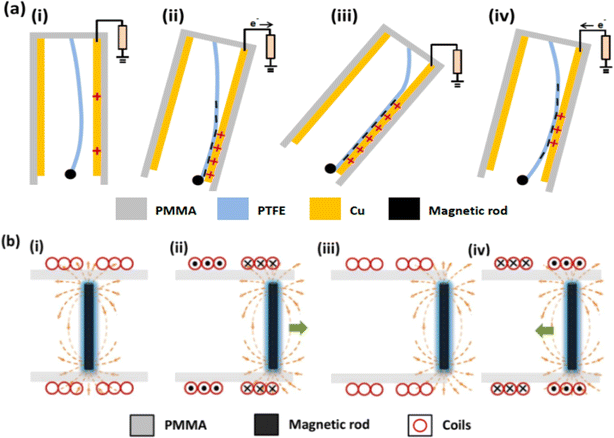
Fig. 1a and c show the schematic diagram and photograph of the HG, respectively. The PTFE surface with nanostructures depicted in Fig. 1b can improve the surface charge density of contact electrification by increasing the surface area between the bent nanostructures of PTFE and the Cu electrode. Fig. 2 illustrates the electricity generation process mechanism of the TENG and EMG nanogenerators, respectively, including the production of short-circuit current, and charge distribution for the TENG (Fig. 2a) and magnetic flux for the EMG (Fig. 2b). As evident from Fig. 2a(i), when the device is stationary, there is no electron transfer between the copper electrode and the grounding terminal. Meanwhile, the magnetic flux in the copper coils does not change as the magnetic bar is in the middle of the bottom track, as shown in Fig. 2b(i); thus no short-circuit current is generated. When the device swings left under the action of waves, a positive potential is generated during the closing of the PTFE film to contact the copper electrode, and electrons flow from the Cu electrode to the ground due to the coupling of surface potential difference and the electrostatic induction effect, as shown in Fig. 2a(ii). At this time, the magnetic flux crossing the copper coil will abate, resulting in an inductive electromotive force produced in the copper coils (Fig. 2b(ii)). When the device oscillates to the maximum angle (Fig. 2a(iii)), electron transfer does not occur in the circuit because an electrostatic balance is reached between the two materials, PTFE film and the copper electrode. For EMG, the unchanged magnetic flux does not induce short-circuit current generated in the coil, as shown in Fig. 2b(iii). When the device recovers from the maximum swing angle, the PTFE film is separated from the right copper electrode, as shown in Fig. 2a(iv). Electrons flow from the ground to the right copper electrode, resulting in an opposite current signal. As the device returns to the initial position, no electric signal is generated. The aforementioned process constitutes half of a swing cycle. As it continues to swing to the right, contact-separation process between PTFE and the left electrode will produce a triboelectric potential. Simultaneously, as the magnetic rod moves to the left, the change in magnetic flux in the copper coils induces the generation of a current signal.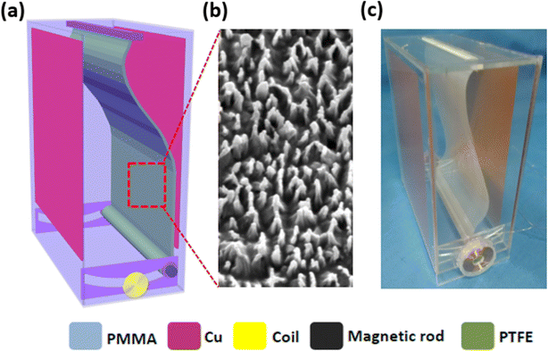 | ||
| Fig. 1 (a) The schematic diagram of structural design and (b) the SEM images of the PTFE surface showing nanostructures. (c) Photograph of the HG. | ||
Output performance of the HG
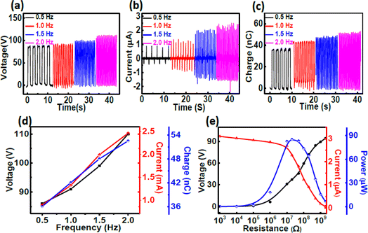
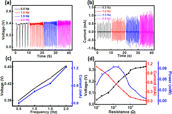
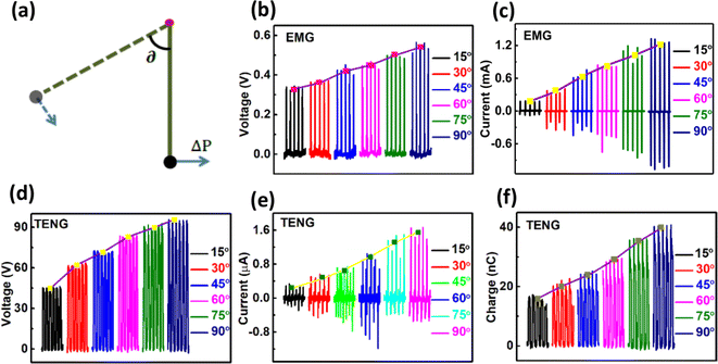
To characterize the performance of harvesting wave energy, the output performance of both the TENG and EMG were measured and analyzed using a programmable linear motor. Fig. 3a–d provide a clear quantitative comparison of the electrical outputs of the TENG at different operation frequencies and oscillation angle of 60 degrees. As the operation frequencies increase from 0.5 to 2.0 Hz, the maximum values of Voc, Isc and Qsc increase from about 88 V, 0.88 μA and 35 nC to about 110 V, 2.4 μA and 45 nC, respectively, as shown in Fig. 3a–c. It is evident that the electrical output signal increases approximately linearly with the increase in operating frequency (Fig. 3d). It is well known that the magnitude of open circuit voltage and transferred charge are related to their contact area.33–35 Given that the oscillation speed increases as the working frequency increases in HG, the improved impulse of the PTFE provides a greater impact force. This results in the increased contact force between PTFE and copper electrode. The transfer rate of the output charge determines the magnitude of short-circuit current. This is because that a higher swing frequency will result in a larger output charge within a shorter time. Fig. 3e depicts the dependence of the output performance of TENG on various load resistances at an operating frequency of 2 Hz and an oscillation angle of 60 degrees. The voltage increases gradually with load, while the current shows an opposite trend. The largest instantaneous peak power of the TENG is about 85.3 μW at a loading resistance of 20 MΩ. Fig. 4 displays the output performance of the EMG under different operation frequencies and an oscillation angle of 60 degrees. The Voc of the EMG increases slowly with the frequency, and its value increases from ∼0.39 V to ∼0.44 V within the operating frequency range of 0.5–2 Hz (Fig. 4a). The Isc of the EMG follows a similar trend to that of voltage, which increases from ∼0.6 to ∼1.22 mA (Fig. 4b). As shown in Fig. 4c, Voc and Isc have an approximate linear relationship with the increase of operating frequency. Based on the theory of electromagnetic induction, the magnitude of Voc increases gradually when the change rate of the magnetic flux increases while the turns of the coil remain constant. The Isc of the EMG increases with the increase in voltage, assuming that the resistivity of the coil is constant. Fig. 4d depicts the dependence of the output power, voltage and current signals on the external variable resistance (with a loading resistance range from 10 to 8000 Ω) at an operating frequency of 2 Hz. The output voltage for the EMG increases as the external resistance load increases, whereas the output current shows the opposite trend. The largest instantaneous power is 95.6 μW at the external loading resistance of up to 200 Ω. The optimal external loading resistance for the EMG does not align with the value of 20 MΩ for the TENG. Usually, a circuit management unit or transformer is employed to address the impedance matching issue between the EMG and TENG in the practical application of HG.The influence of oscillation angle on the output performance of TENG is systematically investigated at the operating frequency of 1 Hz, as depicted in Fig. 5. The Voc, Isc and Qsc of the TENG increase from ∼45 V to ∼96 V, from ∼0.25 μA to ∼1.6 μA, and from ∼18 nC to ∼40 nC, respectively, as the oscillation angle increases from 15 to 90 degree (Fig. 5b–d).
In order to clearly understand the influence of the oscillation angle on the output performance of the TENG, we set up a simple pendulum model, as illustrated in Fig. 5a. The arc length of the swing can be calculated using the following equation:
 | (1) |
 . The running velocity of the device at ∂ = 0 can be obtained from the following formula:
 | (2) |
Merging eqn (1) and (2), we can obtain the running velocity of the device as
 | (3) |
Since the given device mass is constant, its momentum can be expressed as
 | (4) |
Finally, when the device reaches the bottom, the force between PTFE and the copper electrode can be calculated using the following formula
 | (5) |
According to eqn (3), the running speed of the EMG is proportional to the operating frequency. An increase in operating frequency enhances the electrical output performance of the EMG (Fig. 4). Moreover, the running speed of EMG is proportional to the swing angle at an exact operating frequency. The increased rate of change of the magnetic flux in the coils promotes the electrical output performance, as shown in Fig. 5b and c.
According to eqn (5), the force between the PTFE and the copper electrode is proportional to the square of the frequency and the oscillation angle. On the one hand, the increase of frequency is beneficial for improving the electrical output performance of the TENG at a specific swing angle, which is consistent with the measurement results in Fig. 3. On the other hand, the increased contact area of the friction layers from 15 to 90 degree contributes to boosting the electrical output performance of the TENG, as shown in Fig. 5d–f.
Applications
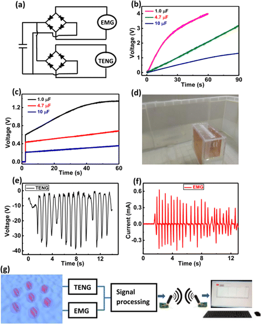
To effectively utilize the capability of the HG consisting of TENG and EMG as a sustainable power source, two full-wave bridge rectifiers connected in parallel were employed to charge different capacitors (1, 4.7, and 10 μF), as shown in Fig. 6a. Fig. 6b demonstrates that larger capacitors charged by the TENG at the frequency of 2 Hz require more charging time.36,37 When the capacitor is charged by the EMG at the frequency of 2 Hz, the voltage is limited by the low open-circuit voltage of EMG and saturates in a short charging time,38,39 as shown in Fig. 6c. To further scale HG for practical applications, the packaged device is placed in a water tank and fixed (Fig. 6d). As depicted in Fig. 6e and f both the output voltage of the TENG and the output current of the EMG exhibit fluctuation characteristics in water waves.According to the output characteristics of the HG, and to further expand the practice application of HG, we propose that the HG arrays be utilized to harvest blue energy for acting as a self-powered ocean wave warning system to monitor the changes of ocean waves. The TENG and EMG produce the voltage and current outputs under ocean waves, which are then transmitted as electric signals to the terminals of the computer or the mobile phone. When the output voltage of the TENG and the output current of the EMG exceed specific set values generated by larger ocean waves, an alarm signal cautions that the ocean waves are too large at that time to venture into the sea. The simulated wave warning process of the HG in the water tank is shown in Videos S1 and S2.†
Conclusions
In summary, a packed box-like hybrid-nanogenerator consisting of two TENGs and two EMGs is designed for harvesting blue ocean energy. The output performances of TENG and EMG increase with an increase in the swing frequency and oscillation amplitude. For the TENG, a larger swing angle means a greater impulse, which improves the friction area of the TENG. For the EMG, the change rate of its magnetic flux increases with the increase in the swing angle. Based on the output characteristics of the HG, the designed HG has potential application in harvesting blue energy, acting as a self-powered wave warning system to monitor the changes in ocean waves.Conflicts of interest
There are no conflicts to declare.Acknowledgements
This work was supported by the National Natural Science Foundation of China (No. 52072111), the Natural Science Foundation of Henan Province in China (No. 212300410004, 232300421211 and 222300420125), the Key Scientific Research Project of Colleges and Universities in Henan Province (23A140024), and the National Research Project Cultivation Foundation of Xuchang University (2023GJPY016).Notes and references
- C. G. Zhang, W. Yuan, B. F. Zhang, J. Y. Yang, Y. X. Hu, L. X. He, X. J. Zhao, X. H. Li, Z. L. Wang and J. Wang, Small, 2023, 2304412 CrossRef CAS PubMed.
- T. Jiang, L. M. Zhang, X. Chen, C. B. Han, W. Tang, C. Zhang, L. Xu and Z. L. Wang, ACS Nano, 2015, 9, 12562 CrossRef CAS PubMed.
- T. Cheng, J. Shao and Z. L. Wang, Nat. Rev. Methods Primers, 2023, 3, 39 CrossRef CAS.
- H. B. Lin, M. H. He, Q. S. Jing, W. F. Yang, S. T. Wang, Y. Liu, Y. L. Zhang, J. Li, N. Li, Y. W. Ma, L. H. Wang and Y. N. Xie, Nano Energy, 2019, 56, 269 CrossRef CAS.
- Z. Wen, J. Chen, M.-H. Yeh, H. Guo, Z. Li, X. Fan, T. Zhang, L. Zhu and Z. L. Wang, Nano Energy, 2015, 16, 38 CrossRef CAS.
- W. Ou-Yang, L. Q. Liu, M. J. Xie, S. Q. Zhou, X. W. Hu, H. Wu, Z. Y. Tian, X. C. Chen, Y. R. Zhu and J. Li, Nano Energy, 2024, 120, 109151 CrossRef.
- X. L. Wei, Z. H. Zhao, C. G. Zhang, W. Yuan, Z. Y. Wu, J. Wang and Z. L. Wang, ACS Nano, 2021, 15, 13200 CrossRef CAS PubMed.
- H. Q. Gao, M. G. Hu, J. F. Ding, B. L. Xia, G. L. Yuan, H. S. Sun, Q. H. Xu, S. Y. Zhao, Y. W. Jiang, H. Wu, M. Yuan, J. H. Li, B. X. Li, J. Zhao, D. W. Rao and Y. N. Xie, Adv. Funct. Mater., 2023, 33, 2213410 CrossRef CAS.
- Y. Zou, Y. S. Gai, P. C. Tan, D. J. Jiang, X. C. Qu, J. T. Xue, H. Ouyang, B. J. Shi, L. L. Li, D. Luo, Y. L. Deng, Z. Li and Z. L. Wang, Fundam. Res., 2022, 2, 619 CrossRef.
- Z. L. Wang, J. Chen and L. Lin, Energy Environ. Sci., 2015, 8, 2250 RSC.
- Y. Zi, S. Niu, J. Wang, Z. Wen, W. Tang and Z. L. Wang, Nat. Commun., 2015, 6, 8376 CrossRef CAS.
- G. Zhu, J. Chen, T. Zhang, Q. Jing and Z. L. Wang, Nat. Commun., 2014, 5, 3426 CrossRef PubMed.
- Z. Li, J. Chen, J. Zhou, L. Zheng, K. C. Pradel, X. Fan, H. Guo, Z. Wen, M.-H. Yeh, C. Yu and Z. L. Wang, Nano Energy, 2016, 22, 548 CrossRef CAS.
- J. Chen, J. Yang, H. Guo, Z. Li, L. Zheng, Y. Su, Z. Wen, X. Fan and Z. L. Wang, ACS Nano, 2015, 9, 12334 CrossRef CAS PubMed.
- C. Wu, X. Wang, L. Lin, H. Guo and Z. L. Wang, ACS Nano, 2016, 10, 4652 CrossRef CAS PubMed.
- J. Wang, Z. Wen, Y. Zi, P. Zhou, J. Lin, H. Guo, Y. Xu and Z. L. Wang, Adv. Funct. Mater., 2016, 26, 1070 CrossRef CAS.
- G. Li, S. K. Fu, C. Y. Luo, P. Wang, Y. Du, Y. T. Tang, Z. Wang, W. C. He, W. L. Liu, H. Y. Guo, J. Chen and C. G. Hu, Nano Energy, 2022, 96, 107068 CrossRef CAS.
- J. M. Liu, N. Y. Cui, T. Du, G. D. Li, S. H. Liu, Q. Xu, Z. Wang, L. Gu and Y. Qin, Nanoscale Adv., 2020, 2, 4482 RSC.
- F. R. Fan, W. Tang and Z. L. Wang, Adv. Mater., 2016, 28, 4283 CrossRef CAS.
- X. J. Zhao, S. Y. Kuang, Z. L. Wang and G. Zhu, ACS Nano, 2018, 12, 4280 CrossRef CAS PubMed.
- Y. C. Hu, H. J. Qiu, Q. J. Sun, Z. L. Wang and L. Xu, Small Methods, 2023, 7, 2300582 CrossRef CAS.
- X. Li, J. Tao, X. Wang, J. Zhu, C. Pan and Z. L. Wang, Adv. Energy Mater., 2018, 8, 1800705 CrossRef.
- X. Sun, C. J. Shang, H. X. Ma, C. Z. Li, L. Xue, Q. Y. Xu, Z. H. Wei, W. L. Li, Y. Yalikun, Y.-C. Lai and Y. Yang, Nano Energy, 2022, 100, 107540 CrossRef CAS.
- S. Y. Wang, P. Xu, J. H. Liu, H. Wang, J. C. Si, J. Deng, M. Y. Xu and Z. L. Wang, Nano Energy, 2023, 118, 109018 CrossRef CAS.
- Y. Wu, Y. Su, J. Bai, G. Zhu, X. Zhang, Z. Li, Y. Xiang and J. Shi, J. Nanomater., 2016, 2016, 1 Search PubMed.
- Q. Gao, Y. H. Xu, X. Yu, Z. X. Jing, T. H. Cheng and Z. L. Wang, ACS Nano, 2022, 16, 6781 CrossRef CAS PubMed.
- C. C. Shan, W. C. He, H. Y. Wu, S. K. Fu, K. X. Li, A. P. Liu, Y. Du, J. Wang, Q. J. Mu, B. Y. Liu, Y. Xi and C. G. Hu, Adv. Funct. Mater., 2023, 33, 2305768 CrossRef CAS.
- S.-T. Chen, J. Hydroinf., 2019, 21, 343 CrossRef.
- D. Yao, X. D. Liang, Q. Meng, J. Li, C. Wu, Z. S. Xie, D. D. Chen and J. P. Guo, Sci. Bull., 2019, 64, 143 CrossRef.
- M.-J. Chang, H.-K. Chang, Y.-C. Chen, G.-F. Lin, P.-A. Chen, J.-S. Lai and Y.-C. Tan, Water, 2018, 10, 1734 CrossRef.
- H. J. Xiao and M. Y. Wei, J. Coastal Res., 2018, 82, 200 CrossRef.
- W. C. Wang, J. C. Xu, H. W. Zheng, F. Q. Chen, K. Jenkins, Y. H. Wu, H. Y. Wang, W. F. Zhang and R. S. Yang, Nanoscale, 2018, 10, 14747 RSC.
- Q. F. Zheng, L. M. Fang, H. Q. Guo, K. F. Yang, Z. Y. Cai, M. A. B. Meador and S. Q. Gong, Adv. Funct. Mater., 2018, 28, 1706365 CrossRef.
- W. C. Wang, J. W. Zhang, Y. J. Zhang, F. Q. Chen, H. Y. Wang, M. J. Wu, H. Li, Q. Y. Zhu, H. W. Zheng and R. Y. Zhang, Appl. Phys. Lett., 2020, 116, 023901 CrossRef.
- Z. L. Wang, Mater. Today, 2017, 20, 74 CrossRef.
- S. M. Niu, Y. Liu, S. H. Wang, L. Lin, Y. S. Zhou, Y. F. Hu and Z. L. Wang, Adv. Mater., 2013, 25, 6184 CrossRef CAS PubMed.
- L. Chen, H. Y. Guo, X. N. Xia, G. L. Liu, H. F. Shi, M. J. Wang, Y. Xi and C. G. Hu, ACS Appl. Mater. Interfaces, 2015, 7, 16450 CrossRef CAS PubMed.
- X. Wang, Z. Wen, H. Y. Guo, C. S. Wu, X. He, L. Lin, X. Cao and Z. L. Wang, ACS Nano, 2016, 10, 11369 CrossRef CAS PubMed.
- X. X. Chen, H. Guo, H. X. Wu, H. T. Chen, Y. Song, Z. M. Su and H. X. Zhang, Nano Energy, 2018, 49, 51 CrossRef CAS.
Footnote |
| † Electronic supplementary information (ESI) available. See DOI: https://doi.org/10.1039/d4na00222a |
| This journal is © The Royal Society of Chemistry 2024 |

