Recent advances in the interfacial engineering of MOF-based mixed matrix membranes for gas separation
Shuwen
Yu
ab,
Conger
Li
bc,
Shuke
Zhao
b,
Milton
Chai
 b,
Jingwei
Hou
 *b and
Rijia
Lin
 *b
*b
aSchool of Chemistry and Chemical Engineering, Suzhou University, Suzhou, 234000, China
bSchool of Chemical Engineering, The University of Queensland, St Lucia, QLD 4072, Australia. E-mail: r.lin1@uq.edu.au; jingwei.hou@uq.edu.au
cSchool of Physical Science and Technology, Shanghai Tech University, Shanghai, 201210, China
First published on 6th March 2024
Abstract
The membrane process stands as a promising and transformative technology for efficient gas separation due to its high energy efficiency, operational simplicity, low environmental impact, and easy up-and-down scaling. Metal–organic framework (MOF)–polymer mixed matrix membranes (MMMs) combine MOFs’ superior gas-separation performance with polymers’ processing versatility, offering the opportunity to address the limitations of pure polymer or inorganic membranes for large-scale integration. However, the incompatibility between the rigid MOFs and flexible polymer chains poses a challenge in MOF MMM fabrication, which can cause issues such as MOF agglomeration, sedimentation, and interfacial defects, substantially weakening membrane separation efficiency and mechanical properties, particularly gas separation. This review focuses on engineering MMMs’ interfaces, detailing recent strategies for reducing interfacial defects, improving MOF dispersion, and enhancing MOF loading. Advanced characterisation techniques for understanding membrane properties, specifically the MOF–polymer interface, are outlined. Lastly, it explores the remaining challenges in MMM research and outlines potential future research directions.
1 Introduction
Membrane separation is an energy-efficient technology with a low carbon footprint, which can be widely adopted in industrial separations.1–3 Polymer membranes stand out as dominant due to their exceptional processability, widespread availability, and satisfactory mechanical properties, making them well-suited for a variety of gas separation applications.3 However, most conventional polymer membranes face an inherent trade-off between the mass transport rates and separation efficiency, on top of operational stability against challenging conditions.1Nanoporous materials, such as zeolites and MOFs, have been considered as potential membrane materials to offer simultaneously high gas permeability and selectivity due to their well-defined pore structures. MOFs have been widely studied as membrane materials due to their large surface area, rich chemical functionality, and tunable pore size and porosity.4 Continuous MOF crystalline membranes showed impressive performance in advanced gas purification, demonstrating potential for precise sieving and breaking the permeation-selectivity trade-off.5–10 Nevertheless, the large-area fabrication of defect-free and selective MOF crystalline membranes remains challenging because controlling the intercrystalline defects and grain boundary is difficult.
In order to overcome the limitations associated with pure polymer or MOF crystalline membranes, MOF-based MMMs have emerged as promising membrane configurations with MOFs as dispersed fillers within the continuous polymer matrix.11 Utilising a polymer matrix offers excellent processability and mechanical stability complemented by nanoporous MOF fillers featuring a tunable pore system for efficient gas transport and molecular sieving, ultimately culminating in a substantial enhancement of membrane separation performance.12,13 Therefore, the selection of the MOF–polymer pair is critical, as it determines the compatibility between the two phases and significantly influences the performance of membrane separation. However, the effective incorporation of MOF fillers into polymer matrices and achieving an ideal interfacial morphology remain difficult because of the intrinsic differences between the MOF and polymer phases. The fabrication of MOF MMMs is often accompanied by the formation of interfacial defects and agglomeration of MOF fillers, especially at high filler loadings (>30 vol%), resulting in deterioration in membrane selectivity and mechanical properties.14,15
Recent advancements in the fabrication of MOF-based MMMs incorporate meticulous interfacial engineering, presenting prospects for scalable MMM production while maintaining exceptional separation capabilities. While there have been several excellent reviews on MOF-based MMMs published previously, this review will cover a gap by also exploring a relatively newer group of MOFs exhibiting glass transition behaviour known as MOF glass.3,13,16,17 This review will place a strong emphasis on the engineering of MOF and polymer interfaces given its importance in improving the gas separation performance (Fig. 1).18 First, a concise discussion of the major technical issues encountered in membrane fabrication will be provided, followed by advanced characterisation techniques to gain an in-depth understanding of the membrane interfacial structure and interactions. Consequently, the most recent design strategies for addressing the interfacial compatibility and MOF dispersion issues are summarised. The last part offers a concise perspective for the future advancement of MMMs and inspires researchers with more strategies to facilitate the implementation of membranes in practical applications.
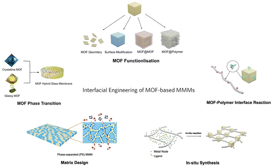 | ||
| Fig. 1 Schematic diagram of the interfacial engineering of MOF-based MMMs (the schematic illustration of the matrix design is reproduced with permission from ref. 18 and copyright 2023 by AAAS Publishing). | ||
2 Challenging fabrication of MOF-based MMMs
While the combination of MOFs and polymers in MMMs holds great promise for advanced membrane applications, addressing the challenges of MOF agglomeration, interfacial compatibility, and mechanical properties in MMMs is crucial for unlocking the full potential of MOFs. This section summarises and compares the preparation methods of MMMs from two perspectives: symmetric MMMs and thin-film nanocomposite (TFN) membranes with an ultrathin MMM layer.A common way to prepare symmetric MMMs is through the solution blending method, which involves the preparation of polymer–MOF suspensions, membrane casting, and solvent removal.14 Some examples of commonly used polymer matrices are PIM-1,19,20 6FDA-polyimide,15,18 Matrimid,21 and Pebax.22 To mitigate the agglomeration of MOF fillers, MOF particles were typically dispersed in a solvent prior to the addition of the polymer. Alternatively, MOFs were dispersed in a solvent and the polymer was dissolved in another solvent separately followed by adding the MOF suspension to the polymer solution.11,16 The after-mixed polymer–MOF suspension was spread onto a level surface through casting or spin coating, followed by solvent evaporation at a specific temperature or pressure. The simplicity of this operation has made it the most extensively used approach for preparing MMMs.
Interfacial issues between the MOF fillers and the polymer matrix are critical in creating desirable MMMs.23 The poor interfacial interaction can lead to nonselective voids or cracks between the two components and damage the performance of the membranes. Various methods have been explored to improve interfacial compatibility, such as modifying MOFs with functional groups or polymer chains,24,25 and using MOF nanosheets with high surface area to volume ratios,15 more specific examples are highlighted in Section 4.
In addition, MOF loading in preparative MMMs is a crucial factor. A greater number of molecular sieving channels can be generated by higher MOF loading, but it is difficult to achieve MMMs with uniformly dispersed MOF fillers due to their agglomeration. To mitigate MOF agglomeration in MMMs, the modulation of MOF fillers is related to the MOF geometry and modification. For example, the MOF geometry can be adjusted by manipulating the synthesis conditions, including the reaction solvent,26 temperature, concentration, and modulators (e.g., acids, bases or surfactant).27,28 At the same time, the amount of MOF loading can also affect the mechanical properties of the membranes. A higher MOF loading often decreases the mechanical integrity provided by the polymer matrix, making it crucial to balance MOF loading and membrane properties. Ultimately, the interfacial issues, MOF loading, and mechanical integrity are closely related and decide the entire separation performance of the membranes. On the other hand, gas permeance is a pivotal membrane parameter that dictates its effectiveness for achieving separation performance.29 It measures the rate at which gas molecules can pass through the membrane and is inversely related to the membrane's thickness. In other words, the thinner the membrane, the faster the gas molecules can penetrate through it. Therefore, TFN membranes, which comprise an ultrathin selective layer of MMMs and a porous support with strong mechanical properties, contribute significantly to enhance gas permeance and overcome the restriction of the mechanical integrity of MMMs.12,23,30,31 Recently, TFN membranes have attracted considerable interest in membrane research owing to the incorporation of distinctive nanofillers and their production scalability.
TFN membranes can be prepared using the in situ interfacial polymerisation technique, which can foster chemical bonding between the polymer and the filler, thereby improving interfacial compatibility.32 Nevertheless, the high concentration of MOF particles in solution poses a challenge due to their poor dispersibility, which easily aggregates on the support surface during the interfacial polymerisation process.33,34 Addressing the challenges associated with agglomerated MOFs in TFN membranes involves surface engineering of MOFs to enhance the dispersity and careful control of production processes to prevent sedimentation and agglomeration. Furthermore, achieving optimal loading of MOF fillers into ultrathin selective layers also poses a challenge, primarily attributed to the brief reaction time between the aqueous and organic phase monomers during the interfacial polymerisation.
To optimise the dispersion of MOF nanofillers and MOF–polymer interfacial compatibility, the utilisation of in situ synthesis for MOF fillers within TFN membranes represents an alternative strategy.14,35 Recent reports indicate that this approach has achieved significant advancements in enhancing interfacial compatibility and MOF loading, resulting in a substantial improvement in separation performance for MOF-based MMMs. In addition, some other techniques, including spin-coating,15,36 dip-coating,37,38 and solution casting,39 were considered to prepare TFN membranes according to their different advantages in lab-scale research and cost-effective processes. For example, Datta et al. prepared a [001]-oriented ultrathin membrane on a porous support with aligned MOF AlFFIVE-1-Ni nanosheets by spin-coating.15 The dip-coating technique is suitable for preparing an ultrathin selective layer on the surface of hollow fibres.37 The solution casting method is ideal for the large-scale and continuous production of TFN membranes. Qiao et al. successfully prepared ultrathin and rollable MOF membranes on a polysulfone (PSf) support with a large area of 2400 cm2 through solution casting followed by MOF growth.40 These studies have shown promise in improving membrane performance by integrating MOF fillers into the ultrathin selective layer of TFN membranes.
In addition, MOF glass is a promising candidate for solving challenges in MOF-based membranes, which can be prepared by melting and then quickly cooling certain MOF crystals.41 Recently, MOF glasses have attracted much attention in MOF crystal–glass composite (CGC)42–45 and MOF glass–polymer composite membranes,46,47 attributed to their high processability, structural tunability, and enhanced porosity. The fascinating properties endow MOF glass with great superiority for eliminating intergrain boundary defects, like crystal lattice mismatches and cracks.
It is important that the efforts made in addressing the different challenges faced in MOF-based MMM fabrication are complemented by appropriate advanced characterisation tools. The following section will discuss the most suitable characterisation techniques that can be used to probe the interfacial properties, defects, MOF loading and dispersion in MOF-based MMMs.
3 Advanced characterisation techniques
Appropriate advanced characterisation techniques are critical in tackling the challenges faced by MMMs by providing a thorough understanding of the MOF and polymer properties and interactions in the interface region. Advanced characterisation techniques offer excellent opportunities to comprehend the interfacial morphologies and interfacial properties of MMMs. This section provides a detailed introduction to the existing techniques for evaluating the MOF–polymer compatibility and determining MOF particle size and distribution within the polymer matrix, quantifying the volume fraction of interfacial defects, probing MOF–MOF and MOF–polymer interfacial interactions, and monitoring the thicknesses and adsorption properties of thin films.3.1 Electron microscopy
Scanning electron microscopy (SEM), transmission electron microscopy (TEM) and tomographic-focused ion beam scanning electron microscopy (FIB-SEM) are critical and extensively employed techniques for characterising membrane interfacial morphologies, in particular for filler distribution and interfacial defects.Scanning electron microscopy (SEM) is a traditional technique applied to qualitatively investigate the dispersion of MOFs and their interfacial issues with the polymer through the morphology of the cross-section of MMMs. In order to obtain SEM samples featuring an exposed membrane cross-section, the membranes are often soaked in liquid nitrogen to induce a brittle fracture. SEM allows for direct visualisation of the MOF distribution and interfacial morphology within the MMMs at a high magnification and resolution. It is important to note that the efficacy of this process highly depends on the polymer's properties, which can influence how quickly and uniformly the polymer cools and contracts, which can, in turn, affect the fracture behaviour and the quality of cross-section images. As a result, it may fail to accurately represent the original structure and properties of the MMMs. On the other hand, cutting the membrane into ultrathin slices, typically ranging from 50 to 150 nm, using an ultramicrotome for TEM analysis is another effective technique. This method facilitates the observation of particle dispersion due to the stark contrast provided by TEM (Fig. 2a–c).48,49 Moreover, it enables the examination of the MOF–polymer interfacial, as shown by the varying degrees of interfacial tears along the direction of the knife cut. These tears occur due to differential shear stress levels experienced during the cutting process, making the mechanical interplay within the composite material more visually discernible.18
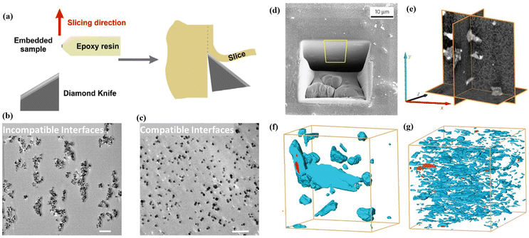 | ||
| Fig. 2 (a) Scheme of cutting ultrathin slices by using ultramicrotome. Reproduced with authorisation from ref. 48 and copyright 2018 by American Chemical Society. (b and c) TEM images of an ultrathin slice (100 nm) of MMMs with incompatible interfaces and compatible interfaces (the scale bar is 1 mm). Reproduced with authorisation from ref. 49 and copyright 2021 by Wiley-VCH GmbH. (d) SEM image of MOF-based MMMs with a trench-formed surface using a FIB. (e) Orthogonal cross-sectional views derived from the 3D-converted FIB-SEM tomogram of the composite material consisting of a MOF and a polymer. Segmented FIB-SEM tomograms of MMMs including MOF fillers with the geometry of bulk type (f) and nanosheets (g). Reproduced with authorisation from ref. 27 and copyright 2015 by Springer Nature. | ||
Tomographic FIB-SEM can quantitatively provide 3D information on the membrane interfacial structure, demonstrating the distribution and volume fraction of various phases within MMMs, including fillers, matrices and interfacial voids/defects.27,50 In this process, a trench is created on the upper surface of the membrane by applying a FIB, followed by capturing a series of SEM images of the cross-sections at sequential intervals during FIB milling. The alignment and stacking of these images allow for the segmentation of individual phases (fillers, matrices and interfacial voids) in the membrane through image thresholding, offering three-dimensional surface-render views and phase distributions of the membrane and providing the volume fraction of interfacial defects. Rodenas et al. used tomographic FIB-SEM to investigate the internal structure of MMMs with different forms of MOF fillers, such as bulk-type nanoparticles or nanosheets (Fig. 2d–g).27 The study results indicate that CuBDC nanosheets were more uniformly dispersed in the polymer than other forms of Cu-BDC when the same amount of a filler was used in the MMMs. Chi et al. introduced branched HKUST-1 nanoparticles into polyimides to form a uniform branched MOF network within the matrix.51 Tomographic FIB-SEM was applied to confirm the connectivity of branched HKUST-1 in the matrix, showing the highly interconnected nanostructures.
3.2 Positron annihilation lifetime spectroscopy (PALS)
PALS can detect pore size information, free volumes, and depth profiles in thin films by using positrons as the probe.52 The technique involves measuring the time between positron implantation and annihilation by detecting the emitted gamma rays (Fig. 3a), and the pore radius can be derived by fitting either a continuous range of lifetimes or a set of discrete lifetimes (Fig. 3b). Compared with other routine physisorption methods, PALS can offer significant flexibility in terms of the material form and sample quantity. Zhu et al. detected the free volume size and distribution in ZIF-8/PIM-1 MMMs using PALS (Fig. 3c).36 Increased pore radii were observed in MMMs compared to those of pristine PIM-1 owing to the porous structure of the MOF (ZIF-8) and loose chain packing after incorporating the MOF into PIM-1. This finding was similar to that of the N2 isotherm test, which confirmed that the chain rearrangement in PIM-1 is crucial to enhance the membrane's ability for molecular sieving. Besides, Yang et al. analysed the correlative pore size distributions of ZIF-62 glass (agfZIF-62) and ZIF-62 glass foam (agfZIF-62) from the PALS data, which proved the improved pore continuity and porosity of agfZIF-62 compared to those of agZIF-62 (Fig. 3d).53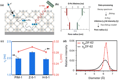 | ||
| Fig. 3 (a) Schematic diagram of PALS for porous materials and (b) pore radius determined by employing an appropriate model based on the ortho-positronium (o-Ps) lifetime. Reproduced with authorisation from ref. 52 and copyright 2021 by Wiley-VCH GmbH. (c) PALS data of PIM-1 membranes with different MOF fillers. Reproduced with authorisation from ref. 36 and copyright 2023 by Springer Nature. (d) Pore size distributions of MOF glasses obtained by PALS. Reproduced with authorisation from ref. 53 and copyright 2023 by Springer Nature. | ||
3.3 X-ray absorption spectroscopy (XAS)
XAS, comprised of X-ray absorption near-edge structure (XANES) and extended X-ray absorption fine structure (EXAFS), can provide insights into the electronic structure and coordination environments of the metals in MOFs and MOF MMMs. Liu et al. studied the coordination properties in MOF crystals and nanosheets using ex situ XAS.54 The result showed that the Cu–O distance in the MOF nanosheets was similar to that in the MOF crystals in the main peak at 1.44 Å, but the peak intensities were reduced according to the extended EXAFS profile (Fig. 4a). Besides, significant changes were found in the peaks of Cu–Cu and Cu–C when comparing MOF nanosheets and crystals. These changes can be ascribed to the irregular coordination between the organic ligands and the metal ions in the MOF nanosheets (Fig. 4b and c). Ao et al. analysed the local structure of Zn in MOF CGC membranes using XAS (Fig. 4d–f).45 The resulting XANES and EXAFS R-plot showed that all MOF CGC membranes had the same coordination numbers and distances, suggesting no new formation of coordination sites.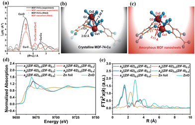 | ||
| Fig. 4 (a) EXAFS spectra of MOF crystals and nanosheets. Suggested structures of (b) MOF crystals and (c) nanosheets deduced from the analysis of EXAFS. Reproduced with authorisation from ref. 54 and copyright 2021 by The Royal Society of Chemistry. (d) Normalized XANES spectra and (e) EXAFS R-plots of MOF CGC membranes. Reproduced with authorisation from ref. 45 and copyright 2023 by Wiley-VCH GmbH. | ||
3.4 Small-angle X-ray scattering (SAXS)
SAXS offers multiple characteristics at the nanometre scale, such as the particle size, shape, distribution, and porous structure, which is an effective approach for analysing the nanoporous structure and filler distribution in MMMs and then obtaining the impact of membrane structure on gas transport properties.55–59Li et al. studied the effect of water in PSf (wet and dry) on the penetrating PDMS layer by analysing the porous structure of the PDMS/PSf composite membrane using SAXS.58 The strong scattering signal arises from the variations of electron density in the membrane, encompassing a radius range of 1–100 nm (Fig. 5a). The pore volume fraction in the PDMS/PSf (dry) (D-100) membrane is less than that in the PSf membrane, suggesting that the infiltrating PDMS occupied specific pores in the PSf membrane that in the D-100 membrane with a radius of 10 to 30 nm (Fig. 5b). Kang et al. investigated the filler dispersion and structure alteration at the nanoscale for MMMs with different MOF (UiO-67 and MIL-140C) loadings by SAXS (Fig. 5c and d).60 The Kratky plot (q vs. q2I) of the poly(glycidyl methacrylate-co-poly(oxyethylene methacrylate)) (PGO) copolymer showed a plateau at an elevated q value, signifying an extended or pliable structure. In contrast, the Kratky plot of MMMs revealed a bell-shaped curve, suggesting a condensed structure. This observation implies that the PGO copolymer matrix proficiently enveloped the evenly dispersed MOF particles. Moreover, it was observed that the diffraction peak position ratio varied for PGO/UiO-67 MMMs, which suggested that the PGO matrix adeptly constrained the UiO-67 particles, causing a modification in the regular arrangement of particles. Nevertheless, the SAXS profiles of PGO/MIL-140C MMMs showed a unique peak, presumably attributed to the substantial and irregular size of the MIL-140C particles.
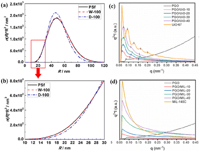 | ||
| Fig. 5 (a and b) Pore volume distributions of PSf, PDMS/PSf (wet) (W-100) and PDMS/PSf (dry) (D-100) membranes. Reproduced with authorisation from ref. 58 and copyright 2019 by Elsevier. (c and d) SAXS patterns of MMMs containing UiO-67 or MIL-140C. Reproduced with authorisation from ref. 60 and copyright 2022 by Elsevier. | ||
3.5 Quartz crystal microbalance (QCM)
A QCM with dissipation is a precise and sensitive technique for analysing the thicknesses and adsorption properties of thin films by monitoring the oscillation of a crystal sensor.61,62 This characterisation method relies on thin piezoelectric quartz crystals that oscillate at a resonance frequency under the influence of an alternating voltage. The oscillation frequency shifts (Δν) in correlation with the increase in film mass caused by adsorption (Δm) (Fig. 6a).52 Song et al. utilised QCM measurements to determine the thickness of the ultrathin selective layer in a thin film composite (TFC) membrane by analysing the ratio of the deposited amount to their density (Fig. 6b).63 To enhance the comprehension of the correlation between the thickness and the C3H6/C3H8 separation performance of 6FDA-DAM TFC membranes, a QCM was also used to investigate the gas sorption properties of these films (Fig. 6c and d).64 The sorption isotherms obtained by the QCM for 6FDA-DAM thin films are closely match with those obtained by the dual-mode sorption model, which confirms the precision and dependability of the QCM technique in assessing the gas sorption characteristics of membrane materials.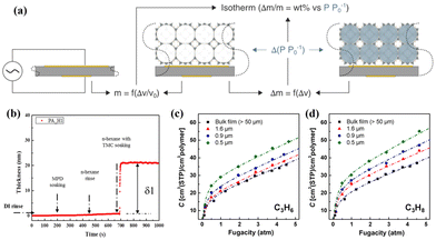 | ||
| Fig. 6 (a) QCM porosimetry. Reproduced with authorisation from ref. 52 and copyright 2021 by Wiley-VCH GmbH. (b) QCMD thickness–time plots of the thin film composite membrane. Reproduced with authorisation from ref. 63 and copyright 2017 by Elsevier. Sorption isotherms of (c) C3H6 and (d) C3H8 for 6FDA-DAM thin films with varying thicknesses determined by the QCM. Reproduced with authorisation from ref. 64 and copyright 2022 by Elsevier. | ||
3.6 Terahertz/far-infrared (THz/far-IR) spectroscopy
THz/far-IR spectroscopy technique has received attention in studying materials’ structural and dynamic properties, such as MOF glass or MOF CGCs.65–67 Hou et al. were the first to use THz/Far-IR to study MOF melting and halogenation within the liquid MOF phase. They found Zn–F bond formation in fluorinated MOF glasses, resulting from the interaction between uncoordinated Zn and F on the benzene ring during the phase transition formation process (Fig. 7a).65 Lin et al. applied THz/Far-IR to investigate the metal–N bonding environment in the crystal and glass state of ZIF-62(Co) and bimetallic MOF (ZIF-62(Co)-Fe) glass, respectively.66 Compared with ZIF-62(Co) crystals and ZIF-62(Co) glass (agZIF-62(Co)) in Fig. 7b, the new peaks of ZIF-62(Co)-Fe crystals and ZIF-62(Co)-Fe glass (agZIF-62(Co)-Fe) at 219 and 344 cm−1, attributed to the Fe–N stretching vibration, conformed the formed Fe–N bonding in the liquid MOF ZIF-62(Co)-Fe state (Fig. 7c). While THz/far-IR spectroscopy has not been used to analyse membrane properties, this technique can be translated into the study of the interfacial properties within the composites. For example, the alterations of interfacial bonding within the mixture of (CsPbI3)0.25(agZIF-62)0.75 were obtained using THz/far-IR.68 Therefore, based on these findings, THz/far-IR can also be effectively used to study the interfacial interactions between the MOF and the polymer in MMMs.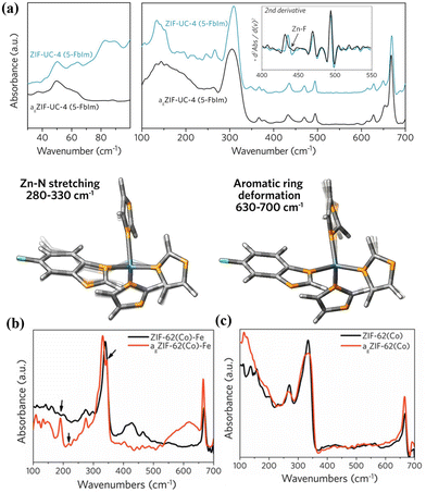 | ||
| Fig. 7 (a) Structure comparison of MOF crystals and glass by THz/far-IR and the modes of ZnIm35-FbIm tetrahedra and aromatic rings utilized in DFT calculations. Reproduced with authorisation from ref. 65 and copyright 2020 by American Chemical Society. THz/Far-IR spectra of the vitrification for (b) ZIF-62(Co)-Fe and (c) ZIF-62(Co). Reproduced with authorisation from ref. 66 and copyright 2022 by Wiley-VCH GmbH. | ||
4 Design strategies of MMMs
Considering the known challenges in fabricating MOF-based MMMs (Section 2) and a suite of advanced characterisation techniques (Section 3) for these membranes, it is worth discussing the various strategies that can be employed to design a high-performing MMM. To fabricate high-performance MMMs, the development of synthetic protocols is highly desirable. Various synthetic strategies, including MOF adjustment, matrix design, the MOF–polymer interfacial reaction, and in situ synthesis, have been employed to improve the filler–matrix compatibility, mitigate particle agglomeration, and maximise MOF loading. In addition, the emerging MOF glass, produced by phase transition of MOF crystals via melt quenching, holds great promise in enhancing the separation performance of membranes by eliminating interface defects.44,454.1 MOF adjustment
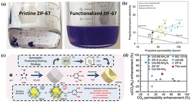 | ||
| Fig. 8 (a) Photo images of pristine and functionalized ZIF-67 in mesitylene. (b) Single- and mixed-gas C3H6/C3H8 separation performances of unmodified MMMs and modified MMMs with various MOF loadings. Reproduced with authorisation from ref. 69 and copyright 2020 by Springer Nature. (c) Illustrative diagram depicting the synthetic process of TA-tailored HZIF-8. (d) Separation performance comparison of different MMMs including MOFs and PIM-1. Reproduced with authorisation from ref. 36 and copyright 2020 by Springer Nature. | ||
Besides introducing functional ligands, ionic liquids can also be used as binding agents to enhance the MOF–polymer adhesion in MMMs.70–72 For example, Gong et al. integrated an amino-functionalised ionic liquid (IL) into ZIF-7-8 particles to form ZIF-7-8-IL, the resulting MMMs showed enhanced interfacial compatibility due to the formation of coordination and hydrogen bonding.71 This coordination involved the ILs correlating with the surface of Zn nodes, facilitating the uniform dispersion of MOF particles. The intentional design of interface interactions using ILs is pivotal for enhancing interface compatibility and the separation performance of CO2/CH4, leading to a significant improvement in the properties of MMMs with 25% ZIF-7-8-IL loading, for example CO2 permeability increased by 291.6%, surpassing the 2018 upper bound.
Modifying MOF surfaces with other MOFs or polymers to construct a hierarchical core–shell structure provides a new platform for precisely tuning the surface properties of MOFs and presents a clear potential for improving MOF dispersibility and interfacial compatibility with the polymer. Wu et al. proposed a dual-interfacial strategy, devising a MOF-801@MOF-74 core–shell structure in the development of MMMs for C2H4/C2H6 separation (Fig. 9a and b).73 Within this core–shell configuration, the MOF-74 shell, featuring high-density open metal sites, played a crucial role in enhancing the filler–polymer interfaces, leading to the development of a defect-free membrane. Simultaneously, the MOF-801 core exhibited a highly selective transport of C2H4. As a result of these synthetic effects, the membrane composed of a MOF-801@MOF-74 core–shell structure exhibits a C2H4/C2H6 separation selectivity of up to 5.91, a 76% increment compared to the pure polymer. Following the rule of “like dissolve like”, MOF@polymers as fillers exhibit excellent dispersibility and enhanced interfacial compatibility through polymer–polymer interactions. Wang et al. functionalised UiO-66-NH2 particles by covalently grafting polyimide (PI) brushes onto them through step-growth polymerisation (Fig. 9c).48 The grafted polymer brushes on MOF surfaces have the same molecular structure as the polymer matrix, leading to a robust brush–brush interaction. With an escalation in MOF loading, the MMMs with PI-grafted structures exhibited a concurrent increase in CO2 permeability and the ideal selectivity for CO2/CH4 and CO2/N2 pairs (Fig. 9d). In contrast, the unmodified MOF-based MMMs showed a sole improvement in permeability but a concurrent loss in selectivity. This indicates that the introduction of PI brushes enhanced the MOF–polymer interface and mitigated defects within the MMMs.
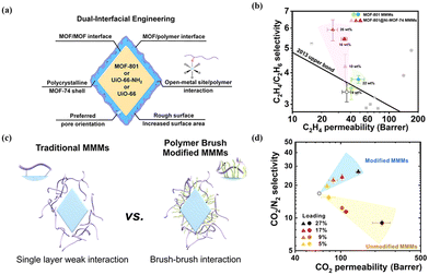 | ||
| Fig. 9 (a) Illustration of the dual-interfacial engineering strategy. (b) C2H4/C2H6 separation performance of MMMs with different core–shell MOF loading. Reproduced with authorisation from ref. 73 and copyright 2020 by American Chemical Society. (c) Comparison of traditional MMMs and PI-grafted MMMs. (d) CO2/N2 separation performances of modified MMMs and unmodified MMMs with various MOF loadings. Reproduced with authorisation from ref. 48 and copyright 2018 by American Chemical Society. | ||
Besides, polymers can be introduced into MOF hosts as guests, resulting in the formation of hybrid materials commonly known as polymer–metal–organic frameworks (polyMOFs).74–76 Lee et al. developed a versatile polyMOF system that uses a microporous polymer ligand derived from polymers of intrinsic microporosity (PIM) by a one-step synthesis (Fig. 10a).25 The polymer ligand plays a dual role, which modulates the properties of polyMOF particles, imparting the framework with angstrom-scale porosity for effectively sieving molecules. In comparison with control MOFs constructed with organic ligands, these polyMOFs demonstrated significant improvements, such as reduced particle size, enhanced ultramicroporosity (3–4 Å), and improved colloidal stability. These unique characteristics make them well-suited for preparing polyMOF/PIM-1 MMMs with high gas separation performance. As expected, the resulting polyMOF/PIM-1 MMMs presented high CO2 separation abilities, which were above the upper bound (Fig. 10b). Moreover, they also investigated the feasibility of upscaling pU20/PIM-1 membranes, and a TFN membrane with a pU20/PIM-1 layer was prepared by a scalable bar-coating method. The resulting pU20/PIM-1 TFN membrane with a large area (20 × 20 cm2) showed a CO2/N2 separation performance that met the target required for CO2 capture. The study demonstrated the potential of the TFN membrane with a pU20/PIM-1 layer in practical CO2/N2 separation processes (Fig. 10c).25
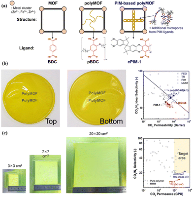 | ||
| Fig. 10 (a) Schematic of the MOF, polymer–MOF (polyMOF), and PIM-based polyMOF system. (b) Optical patterns of pU20/PIM-1 MMMs and their separation performances compared with other membranes. (c) Optical patterns of TFN membranes with a pU20/PIM-1 layer and separation performances compared with other membranes. Reproduced with authorisation from ref. 25 and copyright 2023 by Springer Nature. | ||
MOFs are usually designed with relatively straightforward dimensionalities, including 1D, 2D, or 3D structures. In particular, the 1D configuration facilitates network percolation, the 2D structure allows for the attainment of high aspect ratios, and the 3D arrangement ensures ease of processability. These distinct dimensionalities reflect the versatility of MOF design, allowing for tailored structures that cater to specific applications while optimising membrane separation performance.
High-aspect-ratio 2D MOF nanosheets, such as CuBDC,27,79 ZIF-7,80 Ni-MOF,22,81 NH2-MIL-5382 and AlFFIVE-1-Ni,15 are ideal for fabrication energy-efficient molecular sieve membranes. Their large surface area can improve the interfacial compatibility with the polymer. At the same time, their molecular sieving effect can empower them to function as highly effective selective membranes. Rodenas et al. prepared 2D CuBDC nanosheets using a bottom-up synthesis strategy and the MMMs incorporated with CuBDC nanosheets exhibited excellent CO2 separation from the CO2/CH4 gas mixture.27 Eddaoudi et al. tailored cubic AlFFIVE-1-Ni crystals into 2D nanosheets with maximally exposed (001) facets (Fig. 11a). They found that the loading of MOF AlFFIVE-1-Ni nanosheets in MMMs could be up to 58.9 wt%.15 Their results confirmed the enhanced interfacial compatibility between the MOF nanosheets and the polymer matrix. Moreover, the orientation of MOF nanosheets in MMMs provided parallel channels toward the direction of gas diffusion. These advantages endowed the membrane with ultrahigh gas separation performance, which was far above the upper bounds for polymeric membranes (Fig. 11b). Analogously, Kwon et al. reported the scalable synthesis of ZIF-8 nanoplates with a high aspect ratio by a direct template conversion method.29 As shown in Fig. 11c, ZIF-8 nanoplates were prepared through a process involving the synthesis of a high aspect ratio Zn template known as Zn5(NO3)2(OH)8. The template was then subjected to the introduction of 2-methylimidazole (2-MeIm) linkers, which were dissolved in acetone to facilitate phase conversion. The shape of the nanoplates was maintained by controlling the injection rate of the reactants using syringe pumps. During the synthesis, alkaline ions were added to arrest the shape of Zn5(NO3)2(OH)8. When LiOH is used as the reactant, the Zn5(NO3)2(OH)8 nanosheet results in an 8 μm lateral length. After being incorporated into a 6FDA-DAM polymer matrix through a straightforward bar-coating technique, the separation performance of MMMs loaded with ZIF-8 nanoplates for C3H6/C3H8 far exceeded other reported MMMs (Fig. 11d). Besides, the thermal stability and long-term stability of the ZIF-8 nanoplate/6FDA-DAM MMMs indicated their enormous potential in practical situations.
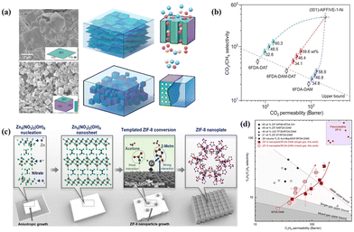 | ||
| Fig. 11 (a) SEM images of MOF nanosheets and crystals and their diagrams in MMMs. (b) CO2/CH4 separation performances of MMMs with different MOF nanosheet loadings and anticipated MOF nanosheet membranes. Reproduced with authorisation from ref. 15 and copyright 2022 by AAAS Publishing. (c) Diagram depicting the synthesis of ZIF-8 nanoplates from Zn5(NO3)2(OH)8 nanosheets. (d) Performance comparison of MMMs with ZIF-8 nanoplates for C3H6/C3H8 separation. Reproduced with authorisation from ref. 29 and copyright 2022 by AAAS Publishing. | ||
Lee et al. revealed that branch-shaped ZIF-8 nanoparticles have a unique morphology that automatically interconnects, which is beneficial for constructing the MOF percolation networks within the polymer matrix at only 20 wt% MOF loading. Compared with the rhombic dodecahedral control ZIF-8, the branched ZIF-8 exhibits a higher surface area-to-volume ratio and allows a strong interaction between the fillers and the polymer, effectively suppressing the mobility of polymer chains. The resulting MMMs exhibited enhanced plasticisation resistance.83
UiO-66 is widely recognised as a MOF with exceptional stability and the structure of this MOF has been extensively tuned and characterised.92 Lee et al. studied the preparation of defective UiO-66-based MMMs by a defect engineering strategy and found that the highly defective UiO-66 nanoparticles, prepared using trifluoroacetic acid as a modulator, presented desirable open metal sites, pore size, pore volume and surface area.85 These properties provide a rapid diffusion pathway and selective adsorption sites for C3H6 due to the existence of Zr–olefin complexation (Fig. 12a). The loading of defect-engineered UiO-66 in the polymer matrix could reach 40 wt%, leading to an increased C3H6 permeability of 365 Barrer without sacrificing C3H6/C3H8 selectivity (Fig. 12b). Besides, they also selected the poly (ethylene glycol) diacrylate (PEGDA) matrix with better gas adsorption capability to fabricate defect-engineered MOF/PEGDA MMMs, and this membrane showed a boosted CO2 permeability of 470 Barrer and an unvaried CO2/N2 selectivity of 41 (Fig. 12c and d).86 Moreover, the incorporation of defect-engineered UiO-66 particles into PIM-1 was carried out to prepare MMMs and the CO2/N2 separation performance was improved due to the enhanced adhesion between the polymer and the defective MOF fillers.19,87
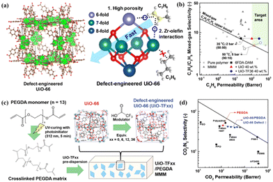 | ||
| Fig. 12 Schematic illustration and separation performance comparison. (a and b) Defect-engineered UiO-66/6FDA-DAM MMMs. Reproduced with authorisation from ref. 85 and copyright 2021 by Wiley-VCH GmbH. (c and d) Defect-engineered UiO-66/PEGDA MMMs. Reproduced with authorisation from ref. 86 and copyright 2021 by Wiley-VCH GmbH. | ||
As another renowned MOF material, defect-engineered ZIF-8 fillers have also been investigated in MMMs to enhance the gas separation performance. An et al. synthesised defect-engineered ZIF-8 nanoparticles using an alkyl amine modulator, which could coordinate with Zn2+ ions (Fig. 13).89 Compared with the routine ZIF-8 particles, defective ZIF-8 particles exhibited more rigid structures, narrower pore size distribution, and smaller openings, which can improve the membrane separation performance. The enhanced dispersibility is mainly attributed to grafting the outer surface with organic alkyl amine molecules. The resulting AZIF8/6FDA-DAM MMMs exhibited exceptional separation performance even as the loading of defective ZIF-8 fillers reached 50%. Apart from ZIF-8, defective Ni-MOF nanosheets also showed uniform dispersion and favourable interfacial compatibility in the Pebax matrix, which exhibited an improved separation performance, in which the CO2 permeability and CO2/CH4 selectivity were 436 Barrer and 33, respectively.22
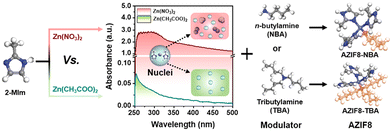 | ||
| Fig. 13 Schematic representation of the synthesis process for alkyl amine-modulated ZIF-8 (AZIF8). Reproduced with authorisation from ref. 89 and copyright 2021 by Wiley-VCH GmbH. | ||
4.2 Matrix design
Polymers can undergo modifications involving the introduction of functional groups to enhance compatibility with MOF fillers, and the common functionalised polymers are PIM-1 and 6FDA-DAM.93,94 Kaliaguine et al. prepared NH2-MIL-53-based MMMs incorporated with hydroxyl groups into 6FDA-DAM to increase interfacial interactions.93 In a combined computational and experimental investigation, Carja et al. explored the MOF–polymer interfacial interactions in MMMs by the combination of UiO-66 and functional PIM-1 modified with various groups, including amidoxime (AO), tetrazole (TZ), and N-((2-ethanolamino)ethyl)carboxamide (EA) (Fig. 14a).94 These studies revealed that hydrogen bonding between the MOF fillers and the functional groups in the polymer chains (Fig. 14b) could improve the polymer–MOF adhesion and enhance the gas separation performance. Moreover, a metal-modified polymer was also considered to engineer MOF–polymer interaction. Fan et al. reported Zn(II)-modified 6FDA-BI/ZIF-8 MMMs with enhanced interfacial interaction due to metal chelation with the nitrogen atom of imidazole groups (Fig. 14c).95 Notably, all the Zn2+ modified membranes presented increased H2/CH4 selectivity.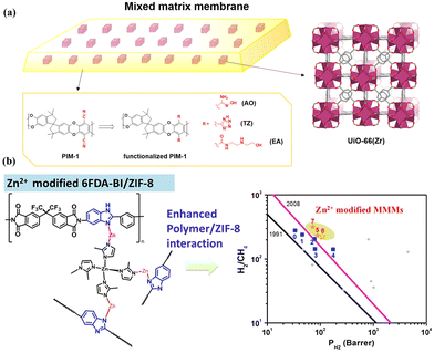 | ||
| Fig. 14 (a) Combination of UiO-66(Zr) fillers and PIM-1 functionalized with AO, TZ and EA. Reproduced with authorisation from ref. 94 and copyright 2021 by American Chemical Society. (b) Metal-modified 6FDA-BI/ZIF-8 MMMs and separation performance comparison. Reproduced with authorisation from ref. 95 and copyright 2022 by Elsevier. | ||
To harness the separation potential of MOFs in MMMs, it is essential to construct a continuous network of MOFs in the polymer matrix. Although it is possible to increase MOF loading (at least 30 wt%) to achieve a percolation network, these membranes are too fragile to be of any practical value unless percolation can be established at a low MOF loading. Li et al. developed a class of phase-separated (PS) MMMs.18 By controlling the phase separation process between two immiscible polymers, the MOF particles can be automatically partitioned and squeezed into the preferred polymer domain at over 50 vol% local packing density, leading to a percolated network with only 19 wt% MOF loading (Fig. 15a). The other polymer phase is free of MOF particles which can serve as a mechanical support to strengthen the membrane. Benefiting from this unique co-continuous morphology, this PS-MMM UiO-66-NH2 exhibited 6.6 times CO2 permeability compared with the pure polymer membrane without giving out its selectivity over N2 and CH4 (Fig. 15b).
 | ||
| Fig. 15 (a) TEM image of phase-separated MMMs with 19 wt% UiO-66-NH2 loading. (b) CO2/N2 separation performance of phase-separated and conventional MMMs with various MOF loadings. Reproduced with authorisation from ref. 18 and copyright 2023 by AAAS Publishing. | ||
4.3 In situ synthesis
![[thin space (1/6-em)]](https://www.rsc.org/images/entities/char_2009.gif) 100 and UiO-66,101 have gained more and more attention.
100 and UiO-66,101 have gained more and more attention.
Park et al. developed a strategy called polymer modification-enabled in situ MOF formation (PMMOF) to improve the interaction between the fillers and the polymers in MMMs.97 The PMMOF strategy involves four key steps: polymer hydrolysis, ion exchange, ligand treatment, and imidization. The in situ ZIF-8 fillers, with an average particle size of approximately 100 nm, displayed a robust affinity with the polyimide matrix, leading to enhanced interactions between the ZIF-8 fillers and the polymer. Moreover, the ZIF-8 loading in MMMs could be up to 32.9% without any noticeable interfacial defects. In a subsequent study, they also reported the in situ growth of ZIF-7 nanoparticles to prepare 6FDA-DAM/ZIF-7 MMMs, resulting in notable enhancements with a 176% increase in H2 permeability and a 180% increase in H2/CO2 selectivity.96 Recently, Li et al. utilised the “confined swelling coupled solvent-controlled crystallisation” method to tailor in situ ZIF-8 crystallisation in polyethylene oxide (PEO) matrix, which formed defect-free channels for CO2 transportation.98 Besides, the chelating interaction between ZIF-8 and PEO improved CO2/N2 selectivity. Consequently, the resulting ZIF-8/PEO membranes exhibited an impressive CO2 permeability of 2490 Barrer, accompanied by a high CO2/N2 selectivity of 37.
In addition, Chen et al.14 prepared an ultrathin and highly loaded MMM with Cu(SiF6)(pyz)3 as a filler via a solid-solvent processing (SSP) strategy. Metal salts were uniformly immobilised within the polymer matrix, acting as a solid solvent, which then undergoes in situ conversion to MOF crystals after ligand vapour treatment. The thickness of Cu(SiF6)(pyz)3@PEG MMM without observable defects could be as thin as 50 nm by facilely controlling the solution properties and coating parameters (Fig. 16a and b). More importantly, the optimised Cu(SiF6)(pyz)3@PEG MMM with 80 vol% loading showed outstanding separation performance, featuring an H2 permeance of 3640 GPU and a H2/CO2 selectivity of 76.1 (Fig. 16c). Besides, they also found that Cu(SiF6)(pyz)3@PEG MMM with 59.6 vol% loading presented high H2/CO2 separation performance, which exceeded the 100 °C upper bound of conventional polymeric membranes and other advanced MOF-based MMMs (Fig. 16d). The solid solvent (polymer) facilitated MOF filler dispersion, ensuring interfacial compatibility between the fillers and the polymer, maintaining the integrity and flexibility of MMMs with high filler loading.
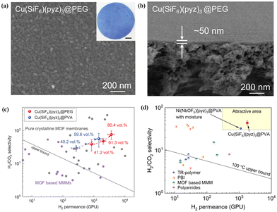 | ||
| Fig. 16 (a and b) Surface and cross-section SEM images of Cu(SiF6)(pyz)3@PEG MMM. (c) Performance comparison of MMMs with different MOF loadings for H2/CO2 separation. (d) Performance comparison of Cu(SiF6)(pyz)3@PVA MMMs, and Ni(NbOF5)(pyz)3@PVA MMMs with other membranes for H2/CO2 separation. Reproduced with authorisation from ref. 14 and copyright 2023 by AAAS Publishing. | ||
In addition, ultraviolet (UV)-induced photopolymerisation can also be applied to in situ synthesise a polymer matrix of MMMs for improved interfacial compatibility and MOF dispersion. For example, ZIF-8 nanoparticles were dispersed in a solution containing poly(ethylene glycol) diacrylate (PEGDA) and poly(ethylene glycol) methyl ether acrylate (PEGMEA) monomers and then subjected to photopolymerisation. This resulted in the rapid formation of solid polymer networks within 30 seconds, preventing nanoparticle aggregation and precipitation during the membrane formation process.104 In another study, Qiao et al. developed a bilayer modification strategy on MOFs to create efficient MOF-based MMMs for C3H6/C3H8 separation. The structure of MOFs can be improved by grafting an octadecylphosphonic acid-lecithin-cholesterol bilayer onto their surface. This enhances their sieving capacity while preserving good interfacial compatibility. In addition, the UV-induced photopolymerisation process promoted the formation of holes in the cross-linked poly(ethylene oxide) (XLPEO) polymer matrix. The resulting MMMs exhibit superior gas permeability and enhanced C3H6/C3H8 selectivity.105
4.4 MOF–polymer interfacial reaction
The interfacial reaction between the MOF fillers and the polymer chains through forming new covalent bonds can provide stronger interactions, facilitating the forming of defect-free membranes. To confirm the significant impact of interfacial reactions, Table 1 lists relevant reports. All the selected literature investigates the effect of covalent bonds on gas separation performance. These studies indicate that the covalently linked MMMs exhibit improved permeability and selectivity compared to the general MMMs. This is primarily due to the improved anti-plasticisation of the polymer and enhanced molecular sieves by highly porous MOFs, which is caused by optimal interfacial interaction between the MOFs and the polymers.| MOF | Polymer | Membrane performance | Ref. | |
|---|---|---|---|---|
| General MMMs | Covalently linked MMMs | |||

|

|
PIM-1: PCO2 = 3027.7 Barrer, SCO2/N2 = 26.6; UiO-66-CN(20 wt%, 200 nm)/PIM-1: PCO2 = 7070.9 Barrer, SCO2/N2 = 26.7; UiO-66-NH2(20 wt%, 200 nm)/sPIM-1: PCO2 = 8619.5 Barrer, SCO2/N2 = 18. | UiO-66-CN(20 wt%, 200 nm)/sPIM-1: PCO2 = 16![[thin space (1/6-em)]](https://www.rsc.org/images/entities/char_2009.gif) 121.3 Barrer, SCO2/N2 = 27. 121.3 Barrer, SCO2/N2 = 27. |
20 |

|

|
PIM-1: PC3H6 = 689.1 Barrer, SC3H6/C3H8 = 5.7; ZIF-8-CN(10 wt%, 80 nm)/PIM-1: PC3H6 = 633.2 Barrer, SC3H6/C3H8 = 5.9; ZIF-8(10 wt%, 80 nm)@tPIM-1: PC3H6 = 417.6 Barrer, SC3H6/C3H8 = 15.6. | ZIF-8-CN(10 wt%, 80 nm)@tPIM-1: PC3H6 = 369.4 Barrer, SC3H6/C3H8 = 27.6. | 106 |

|

|
PIM-1: PCO2 = 6576 Barrer, SCO2/CH4 = 12.3, SCO2/N2 = 18.7; UiO-66(20 wt%, 1 μm)/PIM-1: PCO2 = 7100 Barrer, SCO2/CH4 = 11.6, SCO2/N2 = 16.9. | PIM-co-UiO-6672 h-NH2 (20 wt%, 1 μm): PCO2 = 12![[thin space (1/6-em)]](https://www.rsc.org/images/entities/char_2009.gif) 498 Barrer, SCO2/CH4 = 31.9, SCO2/N2 = 54.2. 498 Barrer, SCO2/CH4 = 31.9, SCO2/N2 = 54.2. |
107 |

|

|
Polyamide TFC membrane: PCO2 = 611 GPU, SCO2/N2 = 107; ZIF-8(1.0 wt%, 700 nm)/Polyamide TFN membrane: PCO2 = 926 GPU, SCO2/N2 = 84. | ZIF-8-NH2(1.0 wt%, 700 nm)/Polyamide TFN membrane: PCO2 = 2004 GPU, SCO2/N2 = 220. | 33 |

|

|
Pure 6FDA-Durene-TAEA: PH2 = 228.7 Barrer, SH2/CO2 = 5.9. | ZIF-90-NH2(45 wt%, 60–100 nm)/6FDA-Durene-TAEA: PH2 = 487 Barrer, SH2/CO2 = 35.8. | 91 |

|

|
Neat COOH-PI: PH2 = 538 Barrer, PCO2 = 368 Barrer, SH2/CH4 = 23.1, SCO2/CH4 = 16. | UiO-66-NH2(20 wt%, 30 nm)/COOH-PI: PH2 = 1180 Barrer, PCO2 = 995 Barrer, SH2/CH4 = 27.2, SCO2/CH4 = 23. | 108 |

|

|
Neat PIM-1: PCO2 = 6576 Barrer, SCO2/CH4 = 12.3, SCO2/N2 = 18.7. | MOF-74(20 wt%, 10–15 μm)/PIM-1: PCO2 = 21![[thin space (1/6-em)]](https://www.rsc.org/images/entities/char_2009.gif) 269 Barrer, SCO2/CH4 = 19.1, SCO2/N2 = 28.7. 269 Barrer, SCO2/CH4 = 19.1, SCO2/N2 = 28.7. |
109 |
Wang et al. detailed the creation of MOF-based MMMs through a covalent-linking strategy to enhance interfacial compatibility.106 The modified ZIF-8 (ZIF-8-CN) could react with PIM-1 upon thermal treatment. The establishment of robust covalent bonds between the fillers and the polymer chains avoided interfacial gaps (Fig. 17a). The MMMs with ZIF-8-CN fillers exhibited an observable enhancement in separation performance with a high C3H6 permeability of 370 Barrer and tripling of the C3H6/C3H8 selectivity to 28, which surpassed the latest upper bound (Fig. 17b). The outstanding permeability and selectivity are attributed to the low gas-transport resistance in the PIM-1 matrix and the molecular sieve effect in ZIF-8-CN fillers. Their permeation mechanism is schematically illustrated in Fig. 17c. The resulting membranes present an excellent promise for the practical separation of C3H6 from C3H8 in industry.
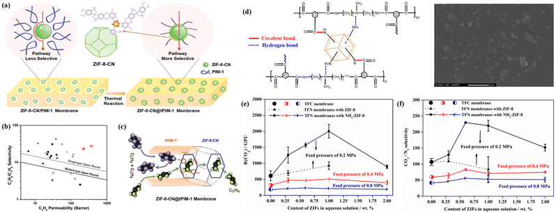 | ||
| Fig. 17 (a) Schematic illustration of the covalent-linking strategy employed for enhancing interfacial compatibility in MMMs. (b) Performance comparison of the ZIF-8-CN@tPIM-1 membrane with other MMMs including ZIF-8. (c) Proposed separation mechanism of the ZIF-8-CN@tPIM-1 membrane for C3H6 and C3H8 separation. Reproduced with authorisation from ref. 106 and copyright 2022 by Wiley-VCH GmbH. (d) Diagram illustrating the formed covalent bonds and hydrogen bonds in the TFN membrane and its surface morphology.(e and f) CO2/N2 separation performance of TFN membranes with different ZIF-8 or ZIF-8-NH2 loadings. Reproduced with authorisation from ref. 33 and copyright 2017 by Elsevier. | ||
Notably, the interfacial reaction approach can combine with the in situ polymerisation strategy since polymer monomers exhibit more crosslinking sites than existing polymers. ZIF-8-NH2 was used to establish covalent bonds with polymer chains during interfacial polymerisation (Fig. 17d).33 ZIF-8-NH2 not only provided a molecular sieve channel, but also disrupted the segment packing in the polymer, creating more free volume and Langmuir gas sorption sites for molecular diffusion. The resulting TFN membrane with ZIF-8-NH2 demonstrated an exceptionally high CO2 permeance of 1572 GPU and a CO2/N2 selectivity of 230 (Fig. 17e and f).
4.5 MOF phase transition
As a recently emerging material, MOF glasses can be melted into a processible liquid state from the crystalline phase at a glass transition temperature, which presents significant potential to fabricate MOF-based MMMs using MOF glass as a continuous phase.41,110 Due to the highly tunable interfacial characteristics, recent research has shown that MOF glass can combine with other functional materials, such as MIL-53,42 ZIF-67,43 and perovskites,68 Therefore, MOF glass becomes a promising membrane, which can be conducive to eliminating intergrain boundary defects.44,111,112Jiang et al. reported a continuous MOF glass membrane prepared through melt-quenching of ZIF-62 crystals for the first time. The resulting ZIF-62 glass membrane presented effective molecular sieving abilities for CO2/N2, H2/CH4, and CO2/CH4 mixtures.112 Wang et al. developed a series of free-standing MOF glass (M-P-dmbIm, M = Zn, Cd, Cu, and Mn) membranes by hot pressing/casting, which showed high H2 separation performance from other gases (CO2, N2, and CH4) and even exceeded the Robeson upper bound (Fig. 18a–c).111 Unfortunately, maintaining the continuity of pores and ultramicro porosity in MOF glass membranes is a significant challenge because of dead-end pores and inherent porosity reduction after melt-quenching treatment. To address this challenge, Qiao et al. reported self-supported ZIF-62 glass foam membranes via a polymer-thermal-decomposition-assisted melting strategy (Fig. 18d).53 The incorporated polyethyleneimine (PEI) with a low molecular weight of only 300 could decompose to produce CO2, NH3 and H2O gases during the thermal process, which induced high interconnected pores in ZIF-62 glass. Thus, the synthesised ZIF-62 glass foam membranes, with a thickness of 200–330 μm and a diameter of 3.3 cm, showed extraordinary gas separation performance with a CH4 permeance of 30![[thin space (1/6-em)]](https://www.rsc.org/images/entities/char_2009.gif) 000–50
000–50![[thin space (1/6-em)]](https://www.rsc.org/images/entities/char_2009.gif) 000 GPU and a CH4/N2 selectivity of 4–6 (Fig. 18e). Notably, the CH4 permeance was approximately two orders of magnitude higher than that observed in other reported membranes with similar CH4/N2 selectivity (Fig. 18f).
000 GPU and a CH4/N2 selectivity of 4–6 (Fig. 18e). Notably, the CH4 permeance was approximately two orders of magnitude higher than that observed in other reported membranes with similar CH4/N2 selectivity (Fig. 18f).
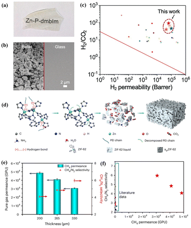 | ||
| Fig. 18 (a and b) Photograph and SEM images of the MOF pellet and the MOF glass membrane. (c) Separation performance comparison of MOF glass with other gas separation membranes. Reproduced with authorisation from ref. 111 and copyright 2021 by Wiley-VCH GmbH. (d) Schematic illustration for forming MOF glass membranes by PEI decomposition. (e) CH4/N2 permeance and selectivity of MOF glass membranes with different thicknesses. (f) Performance comparison of MOF glass membranes with other high-performance membranes. Reproduced with authorisation from ref. 53 and copyright 2023 by Springer Nature. | ||
Glass MOFs offer an alternative approach through in situ melting. The MOF liquid state has metal nodes and organic ligands, promoting bonding and minimising interfacial defects between the MOFs and the polymers. We reported 6FDA-DAM/ZIF-62 glass MMMs prepared by melt quenching and vitrification of ZIF-62 crystals in a 6FDA-DAM matrix.46 The results proved that the melting of ZIF-62 could fill the cracks at the MOF–polymer interface. Moreover, the newly formed Zn–O and Zn–F bonding between ZIF-62 glass and 6FDA-DAM enhanced the interfacial compatibility and improved the rigidity of 6FDA-DAM, leading to increased CO2/N2 selectivity.
Another significant strategy involves employing MOF glass as a continuous phase to prepare MMMs for improving interfacial compatibility with incorporated fillers. ZIF-8 was initially blended with ZIF-62 to form composite membranes with porous alumina as the support and the C3H6/C3H8 selectivity increased from 2.5 of neat ZIF-62 to 17.44 Qiao et al. synthesised a self-supported MMM using a combination of ZIF-8 crystals and ZIF-62 glass (Fig. 19a).45 ZIF-62 crystals could convert into glass while ZIF-8 maintained the crystal state during the thermal process, which could diminish grain boundary defects and improve separation selectivity. The obtained ZIF-8/ZIF-62 composite membranes showed an ultrahigh separation performance, due to the abundant pore structure and the preferential adsorption for C2H6 (Fig. 19b and c).
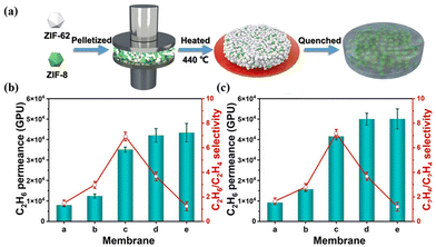 | ||
| Fig. 19 (a) Preparation process of ZIF-8/ZIF-62 CGC membranes. (b) Mixed and (c) pure gas separation performance of ZIF-8/ZIF-62 CGC membranes. Reproduced with authorisation from ref. 45 and copyright 2023 by Wiley-VCH GmbH. | ||
5 Conclusions and perspectives
MOF-based MMMs have emerged as potentially effective compounds for enhancing membrane separation capabilities and facilitating the industrial scale-up process. This is mainly attributed to the outstanding sieving properties of MOFs, which enable them to function as molecular sieves, leading to the separation performance. This review highlighted the different designs and optimised strategies of preparing MMMs with MOF fillers for improving separation performance, and their cutting-edge advances for separation have been overviewed. Potential future directions for exploring new developments and the practical applications of MOF-based membranes are discussed.Further research on 2D MOF nanosheets should be conducted to direct the development of 2D MOF-based MMMs. Advanced composite materials using oriented 2D nanosheets have created MMMs with high separation performance because their high aspect ratio can improve the packing density.15 The application of 2D MOF-based MMMs is not only for gas separation but also for nanofiltration113 and ion separation.114 It is important to note that although oriented 2D MOF nanosheets can endow MMMs with high separation performance, only a few examples, such as AlFFIVE-1-Ni15 and ZIF-95,115 have been reported. The development of 2D MOF-based MMMs is hindered by various challenges faced by 2D MOF nanosheets. These challenges can be broadly divided into three aspects. First, there needs to be more clarity on the conformational relationships of 2D MOF nanosheets, which makes it challenging to synthesise high-quality nanosheets using controlled synthesis strategies. Second, current exfoliation techniques risk the structural integrity of MOF nanosheets, and their low monolayer yield hinders large-scale application. Third, the fragile structure and poor stability of 2D MOF nanosheets must be improved to make them practically applicable. Overcoming these challenges will open new avenues for producing high-performance 2D MOF-based MMMs.
Cutting-edge MOF-based MMMs featuring extremely thin, distinctive structures hold promise for achieving remarkable permeance and selectivity. However, manufacturing such thin membranes remains challenging during the scale-up process, particularly for MMMs with a thickness at the nanoscale. There are two critical points to consider regarding ultrathin membranes. First, thinner membranes lead to higher permeance, but this relationship becomes more complex at the nanoscale. Designing membranes for specific applications requires understanding the interplay between the thickness, surface effects, and other factors. Second, the long-term durability of most ultrathin MMMs is not well established. Research progress on ultrathin MOF-based MMMs has continued over the past decade, accelerated by nanotechnology. For instance, the MOF-based MMMs prepared through the gravity-induced interface self-assembly method exhibited exceptional CO2/N2 separation performance due to the ultrathin and unobstructed gas transport channels.116 This design concept and approach can be applied to manufacture other MMMs using various porous fillers or polymer matrices to achieve better membrane performance. In addition, Chen et al. developed a promising SSP strategy for the fabrication of ultrathin MOF-based MMMs.14 This approach not only addresses persistent processability issues, but also offers the potential for exploring industrially applicable membrane configurations and contributing to the field of membrane separation technology. Therefore, the state-of-the-art reports about ultrathin MOF-based MMMs will play a significant role in industrial separation with addressed issues.
On the other hand, the emerging MOF glasses open a new avenue for fabricating defect-free MOF-based MMMs with MOF glass as a matrix. Though only a few research studies investigated MOF CGC membranes (e.g., ZIF-8/ZIF-62),44,45 the successful utilisation of MOF glass in gas separation membranes has proven their enormous potential in the field of membrane separation.53,112 For example, constructive MOF glass foam membranes provided abundantly unsaturated Zn2+ ions, which could induce preferential van der Waals interactions with CH4 compared with N2, facilitating the selective transport of CH4 molecules through the membrane. Besides, the improved porosity and the existence of unsaturated metal centres in MOF glass make them suitable for gas separation and applications in ion separation and chemical catalysis.41,117 Furthermore, we anticipate that additional modification techniques for MMMs with MOF glass as a matrix will be reported and implemented in the industry in the near future.
Molecular modelling and simulation are crucial for understanding membrane materials, such as structural design, formation conditions, and separation mechanisms. Combining advanced molecular simulation with realistic structure modelling of MMMs can reveal relationships between the membrane components and the performance, leading to precise separations for various industries. Molecular simulations can be used positively in developing screening studies to overcome the limitations in membrane preparation and experimental characterisation. Recently, molecular simulations have presented the potential to develop high-performance MMMs by computational screening and deep-analysis fundamental methods. In the future, research efforts with advanced computational resources can analyse the relationship of molecule adsorption and transport with membrane characteristics, including structural modification, filler distribution, and interfacial interactions.
Significant breakthroughs are required for more diverse and extensive applications of MMMs. Although there are currently no industrial applications of MOF-based MMMs for molecule separation, the improved interfacial compatibility in MOF–polymer or MOF crystal–glass is expected to hasten their industrial implementation. Some reports have proved that MOF-based MMMs are expected to achieve large-scale preparation. For example, Chen et al. scaled up the fabrication of flat-sheet MOF-based MMMs on a polyacrylonitrile substrate to an area of 720 cm2 using the SSP strategy.14 The resulting stable separation performance highlighted the potential for large-scale applications. Qiao et al. achieved MMM modules with a large area of ca. 2000 cm2 and 85 wt% ZIF-8 loading, which exhibited outstanding separation performance.118 However, only a few MOF materials are suitable for large-scale MMM production. Therefore, more effort must be made to meet practical application requirements by the fundamental design rules and screening appropriate membrane materials.
Conflicts of interest
There are no conflicts to declare.Acknowledgements
The authors acknowledge the funding support from the Australian Research Council (ARC) (DE230100173, FT210100589, and DP230101901), the Excellent Youth Research Project of Anhui province (2022AH030135 and 2022AH020083), the PhD Research Funding of Suzhou University (2021BSK041 and 2020BS019), the Natural Science Foundation of Anhui province (2108085MB67) and the China Scholarship Council (CSC).References
- H. B. Park, J. Kamcev, L. M. Robeson, M. Elimelech and B. D. Freeman, Science, 2017, 356, eaab0530 CrossRef PubMed.
- C. Zhang, B.-H. Wu, M.-Q. Ma, Z. Wang and Z.-K. Xu, Chem. Soc. Rev., 2019, 48, 3811–3841 RSC.
- Y. Cheng, S. J. Datta, S. Zhou, J. Jia, O. Shekhah and M. Eddaoudi, Chem. Soc. Rev., 2022, 51, 8300–8350 RSC.
- G. Chen, G. Liu, Y. Pan, G. Liu, X. Gu, W. Jin and N. Xu, Chem. Soc. Rev., 2023, 52, 4586–4602 RSC.
- W. Fan, Y. Ying, S. B. Peh, H. Yuan, Z. Yang, Y. D. Yuan, D. Shi, X. Yu, C. Kang and D. Zhao, J. Am. Chem. Soc., 2021, 143, 17716–17723 CrossRef CAS PubMed.
- X. Ma, P. Kumar, N. Mittal, A. Khlyustova, P. Daoutidis, K. A. Mkhoyan and M. Tsapatsis, Science, 2018, 361, 1008–1011 CrossRef CAS PubMed.
- Z. Qiao, Y. Liang, Z. Zhang, D. Mei, Z. Wang, M. D. Guiver and C. Zhong, Adv. Mater., 2020, 32, 2002165 CrossRef CAS PubMed.
- Y. Peng, Y. Li, Y. Ban, H. Jin, W. Jiao, X. Liu and W. Yang, Science, 2014, 346, 1356–1359 CrossRef CAS PubMed.
- H. Song, Y. Peng, C. Wang, L. Shu, C. Zhu, Y. Wang, H. He and W. Yang, Angew. Chem., Int. Ed., 2023, 62, e202218472 CrossRef CAS PubMed.
- S. Zhou, O. Shekhah, J. Jia, J. Czaban-Jóźwiak, P. M. Bhatt, A. Ramírez, J. Gascon and M. Eddaoudi, Nat. Energy, 2021, 6, 882–891 CrossRef CAS.
- R. Lin, B. V. Hernandez, L. Ge and Z. Zhu, J. Mater. Chem. A, 2018, 6, 293–312 RSC.
- W. J. Koros and C. Zhang, Nat. Mater., 2017, 16, 289–297 CrossRef CAS PubMed.
- Q. Qian, P. A. Asinger, M. J. Lee, G. Han, K. M. Rodriguez, S. Lin, F. M. Benedetti, A. X. Wu, W. S. Chi and Z. P. Smith, Chem. Rev., 2020, 120, 8161–8266 CrossRef CAS PubMed.
- G. Chen, C. Chen, Y. Guo, Z. Chu, Y. Pan, G. Liu, G. Liu, Y. Han, W. Jin and N. Xu, Science, 2023, 381, 1350–1356 CrossRef CAS PubMed.
- S. J. Datta, A. Mayoral, N. M. S. Bettahalli, P. M. Bhatt, M. Karunakaran, I. D. Carja, D. Fan, M. M. P. Graziane, R. Semino, G. Maurin, O. Terasaki and M. Eddaoudi, Science, 2022, 376, 1080–1087 CrossRef CAS PubMed.
- S. H. Goh, H. S. Lau and W. F. Yong, Small, 2022, 18, 2107536 CrossRef CAS PubMed.
- L. Hu, K. Clark, T. Alebrahim and H. Lin, J. Membr. Sci., 2022, 644, 120140 CrossRef CAS.
- C. Li, A. Qi, Y. Ling, Y. Tao, Y.-B. Zhang and T. Li, Sci. Adv., 2023, 9, eadf5087 CrossRef CAS PubMed.
- C. Geng, Y. Sun, Z. Zhang, Z. Qiao and C. Zhong, ACS Sustainable Chem. Eng., 2022, 10, 3643–3650 CrossRef CAS.
- G. Yu, X. Zou, L. Sun, B. Liu, Z. Wang, P. Zhang and G. Zhu, Adv. Mater., 2019, 31, 1806853 CrossRef PubMed.
- A. Akbari, J. Karimi-Sabet and S. M. Ghoreishi, Chem. Eng. Process., 2020, 148, 107804 CrossRef CAS.
- W. Zhu, L. Wang, H. Cao, R. Guo and C. Wang, J. Membr. Sci., 2023, 669, 121305 CrossRef CAS.
- Z. Yang and D. Zhao, Science, 2023, 381, 1288–1289 CrossRef CAS PubMed.
- J. H. Jo, C. O. Lee, G. Y. Ryu, H. Jae, D. Roh and W. S. Chi, ACS Appl. Polym. Mater., 2022, 4, 6426–6439 CrossRef CAS.
- T. H. Lee, B. K. Lee, S. Y. Yoo, H. Lee, W.-N. Wu, Z. P. Smith and H. B. Park, Nat. Commun., 2023, 14, 8330 CrossRef PubMed.
- S. Japip, Y. Xiao and T.-S. Chung, Ind. Eng. Chem. Res., 2016, 55, 9507–9517 CrossRef CAS.
- T. Rodenas, I. Luz, G. Prieto, B. Seoane, H. Miro, A. Corma, F. Kapteijn, I. X. F. X. Llabres and J. Gascon, Nat. Mater., 2015, 14, 48–55 CrossRef CAS PubMed.
- S. Feng, M. Bu, J. Pang, W. Fan, L. Fan, H. Zhao, G. Yang, H. Guo, G. Kong, H. Sun, Z. Kang and D. Sun, J. Membr. Sci., 2020, 593, 117404 CrossRef.
- O. Kwon, M. Kim, E. Choi, J. H. Bae, S. Yoo, J. C. Won, Y. H. Kim, J. H. Shin, J. S. Lee and D. W. Kim, Sci. Adv., 2022, 8, eabl6841 CrossRef CAS PubMed.
- D. L. Zhao, F. Feng, L. Shen, Z. Huang, Q. Zhao, H. Lin and T.-S. Chung, Chem. Eng. J., 2023, 454, 140447 CrossRef CAS.
- A. Knebel and J. Caro, Nat. Nanotechnol., 2022, 17, 911–923 CrossRef CAS PubMed.
- Z. Liao, X. Fang, Q. Li, J. Xie, L. Ni, D. Wang, X. Sun, L. Wang and J. Li, J. Membr. Sci., 2020, 594, 117468 CrossRef CAS.
- S. Yu, S. Li, S. Huang, Z. Zeng, S. Cui and Y. Liu, J. Membr. Sci., 2017, 540, 155–164 CrossRef CAS.
- E. L. Butler, C. Petit and A. G. Livingston, J. Membr. Sci., 2020, 596, 117482 CrossRef CAS.
- Y. Hua, S. Park, G. M. Choi, H. J. Jung, K. Y. Cho and H.-K. Jeong, Chem. Eng. J., 2023, 466, 143048 CrossRef CAS.
- B. Zhu, S. He, Y. Yang, S. Li, C. H. Lau, S. Liu and L. Shao, Nat. Commun., 2023, 14, 1697 CrossRef CAS PubMed.
- P. D. Sutrisna, J. Hou, M. Y. Zulkifli, H. Li, Y. Zhang, W. Liang, D. M. D'Alessandro and V. Chen, J. Mater. Chem. A, 2018, 6, 918–931 RSC.
- A. Mousavinejad, A. Rahimpour, M. R. S. Kebria, S. K. Salestan, M. Sadrzadeh and N. T. H. Kiadeh, Ind. Eng. Chem. Res., 2020, 59, 12834–12844 CrossRef CAS.
- C. Ma, Z. Yang, X. Guo, Z. Qiao and C. Zhong, J. Membr. Sci., 2022, 663, 121069 CrossRef CAS.
- C. Yu, X. Cen, Z. Zhang, Y. Sun, W. Xue, Z. Qiao, M. D. Guiver and C. Zhong, Adv. Mater., 2023, 35, 2307013 CrossRef CAS PubMed.
- R. Lin, M. Chai, Y. Zhou, V. Chen, T. D. Bennett and J. Hou, Chem. Soc. Rev., 2023, 52, 4149–4172 RSC.
- J. Hou, C. W. Ashling, S. M. Collins, A. Krajnc, C. Zhou, L. Longley, D. N. Johnstone, P. A. Chater, S. Li, M. V. Coulet, P. L. Llewellyn, F. X. Coudert, D. A. Keen, P. A. Midgley, G. Mali, V. Chen and T. D. Bennett, Nat. Commun., 2019, 10, 2580 CrossRef PubMed.
- S. Li, S. Yu, S. M. Collins, D. N. Johnstone, C. W. Ashling, A. F. Sapnik, P. A. Chater, D. S. Keeble, L. N. McHugh, P. A. Midgley, D. A. Keen and T. D. Bennett, Chem. Sci., 2020, 11, 9910–9918 RSC.
- Y. Zhang, Y. Wang, H. Xia, P. Gao, Y. Cao, H. Jin and Y. Li, Chem. Commun., 2022, 58, 9548–9551 RSC.
- D. Ao, Z. Yang, Z. Qiao, Y. Sun, Z. Zhang, M. D. Guiver and C. Zhong, Angew. Chem., Int. Ed. Engl., 2023, 135, e202304535 CrossRef.
- R. Lin, J. Hou, M. Li, Z. Wang, L. Ge, S. Li, S. Smart, Z. Zhu, T. D. Bennett and V. Chen, Chem. Commun., 2020, 56, 3609–3612 RSC.
- Y. Feng, W. Yan, Z. Kang, X. Zou, W. Fan, Y. Jiang, L. Fan, R. Wang and D. Sun, Chem. Eng. J., 2023, 465, 142873 CrossRef CAS.
- H. Wang, S. He, X. Qin, C. Li and T. Li, J. Am. Chem. Soc., 2018, 140, 17203–17210 CrossRef CAS PubMed.
- C. Li, J. Liu, K. Zhang, S. Zhang, Y. Lee and T. Li, Angew. Chem., Int. Ed., 2021, 60, 14138–14145 CrossRef CAS PubMed.
- T. Rodenas, M. van Dalen, E. García-Pérez, P. Serra-Crespo, B. Zornoza, F. Kapteijn and J. Gascon, Adv. Funct. Mater., 2014, 24, 249–256 CrossRef CAS.
- W. S. Chi, B. J. Sundell, K. Zhang, D. J. Harrigan, S. C. Hayden and Z. P. Smith, ChemSusChem, 2019, 12, 2355–2360 CrossRef CAS PubMed.
- T. Stassin, R. Verbeke, A. J. Cruz, S. Rodriguez-Hermida, I. Stassen, J. Marreiros, M. Krishtab, M. Dickmann, W. Egger, I. F. J. Vankelecom, S. Furukawa, D. De Vos, D. Grosso, M. Thommes and R. Ameloot, Adv. Mater., 2021, 33, 2006993 CrossRef CAS PubMed.
- Z. Yang, Y. Belmabkhout, L. N. McHugh, D. Ao, Y. Sun, S. Li, Z. Qiao, T. D. Bennett, M. D. Guiver and C. Zhong, Nat. Mater., 2023, 22, 888–894 CrossRef CAS PubMed.
- M. Liu, K. Xie, M. D. Nothling, L. Zu, S. Zhao, D. J. E. Harvie, Q. Fu, P. A. Webley and G. G. Qiao, ACS Cent. Sci., 2021, 7, 671–680 CrossRef CAS PubMed.
- T. Li, A. J. Senesi and B. Lee, Chem. Rev., 2016, 116, 11128–11180 CrossRef CAS PubMed.
- H. C. Liao, C. S. Tsao, T. H. Lin, C. M. Chuang, C. Y. Chen, U. S. Jeng, C. H. Su, Y. F. Chen and W. F. Su, J. Am. Chem. Soc., 2011, 133, 13064–13073 CrossRef CAS PubMed.
- H.-C. Liao, C.-S. Tsao, T.-H. Lin, M.-H. Jao, C.-M. Chuang, S.-Y. Chang, Y.-C. Huang, Y.-T. Shao, C.-Y. Chen and C.-J. Su, ACS Nano, 2012, 6, 1657–1666 CrossRef CAS PubMed.
- S. Li, H. Zhang, S. Yu, J. Hou, S. Huang and Y. Liu, Sep. Purif. Technol., 2019, 211, 252–258 CrossRef CAS.
- Y. Ying, S. B. Peh, H. Yang, Z. Yang and D. Zhao, Adv. Mater., 2022, 34, 2104946 CrossRef CAS PubMed.
- M. Kang, T.-H. Kim, H. H. Han, H. J. Min, Y.-S. Bae and J. H. Kim, J. Membr. Sci., 2022, 659, 120788 CrossRef CAS.
- H. A. Huellemeier, N. M. Eren, J. Ortega-Anaya, R. Jimenez-Flores and D. R. Heldman, Chem. Eng. Sci., 2022, 247, 117004 CrossRef CAS.
- X. K. Li, G. P. Cao, L. H. Chen, R. H. Zhang, H. L. Liu and Y. H. Shi, Langmuir, 2013, 29, 14089–14100 CrossRef CAS PubMed.
- X. Song, S. Qi, C. Y. Tang and C. Gao, J. Membr. Sci., 2017, 540, 10–18 CrossRef CAS.
- T. H. Lee, M. G. Shin, J. G. Jung, E. H. Suh, J. G. Oh, J. H. Kang, B. S. Ghanem, J. Jang, J.-H. Lee, I. Pinnau and H. B. Park, J. Membr. Sci., 2022, 645, 120215 CrossRef CAS.
- J. Hou, M. L. R. Gómez, A. Krajnc, A. McCaul, S. Li, A. M. Bumstead, A. F. Sapnik, Z. Deng, R. Lin, P. A. Chater, D. S. Keeble, D. A. Keen, D. Appadoo, B. Chan, V. Chen, G. Mali and T. D. Bennett, J. Am. Chem. Soc., 2020, 142, 3880–3890 CrossRef CAS PubMed.
- R. Lin, X. Li, A. Krajnc, Z. Li, M. Li, W. Wang, L. Zhuang, S. Smart, Z. Zhu, D. Appadoo, J. R. Harmer, Z. Wang, A. G. Buzanich, S. Beyer, L. Wang, G. Mali, T. D. Bennett, V. Chen and J. Hou, Angew. Chem., Int. Ed., 2022, 61, e202112880 CrossRef CAS PubMed.
- X. Li, W. Huang, A. Krajnc, Y. Yang, A. Shukla, J. Lee, M. Ghasemi, I. Martens, B. Chan, D. Appadoo, P. Chen, X. Wen, J. A. Steele, H. G. Hackbarth, Q. Sun, G. Mali, R. Lin, N. M. Bedford, V. Chen, A. K. Cheetham, L. H. G. Tizei, S. M. Collins, L. Wang and J. Hou, Nat. Commun., 2023, 14, 7612 CrossRef CAS PubMed.
- J. Hou, P. Chen, A. Shukla, A. Krajnc, T. Wang, X. Li, R. Doasa, L. H. Tizei, B. Chan and D. N. Johnstone, Science, 2021, 374, 621–625 CrossRef CAS PubMed.
- A. Knebel, A. Bavykina, S. J. Datta, L. Sundermann, L. Garzon-Tovar, Y. Lebedev, S. Durini, R. Ahmad, S. M. Kozlov, G. Shterk, M. Karunakaran, I. D. Carja, D. Simic, I. Weilert, M. Kluppel, U. Giese, L. Cavallo, M. Rueping, M. Eddaoudi, J. Caro and J. Gascon, Nat. Mater., 2020, 19, 1346–1353 CrossRef CAS PubMed.
- Z. Yang, Y. Ying, Y. Pu, D. Wang, H. Yang and D. Zhao, Ind. Eng. Chem. Res., 2022, 61, 7626–7633 CrossRef CAS.
- L. Gong, Z. Cai, Q. Wu, L. Liu, C. Wang, L. Shan, X. Meng, S. Luo, Z. Liu and S. Zhang, J. Mater. Chem. A, 2022, 10, 24975–24984 RSC.
- N. Habib, O. Durak, M. Zeeshan, A. Uzun and S. Keskin, J. Membr. Sci., 2022, 658, 120712 CrossRef CAS.
- C. Wu, K. Zhang, H. Wang, Y. Fan, S. Zhang, S. He, F. Wang, Y. Tao, X. Zhao, Y.-B. Zhang, Y. Ma, Y. Lee and T. Li, J. Am. Chem. Soc., 2020, 142, 18503–18512 CrossRef CAS PubMed.
- Y. Gu, M. Huang, W. Zhang, M. A. Pearson and J. A. Johnson, Angew. Chem., Int. Ed., 2019, 58, 16676–16681 CrossRef CAS PubMed.
- A. Karmakar, P. G. Mileo, I. Bok, S. B. Peh, J. Zhang, H. Yuan, G. Maurin and D. Zhao, Angew. Chem., Int. Ed., 2020, 59, 11003–11009 CrossRef CAS PubMed.
- M. Kalaj, K. C. Bentz, S. Ayala Jr., J. M. Palomba, K. S. Barcus, Y. Katayama and S. M. Cohen, Chem. Rev., 2020, 120, 8267–8302 CrossRef CAS PubMed.
- L. Ge, W. Zhou, V. Rudolph and Z. Zhu, J. Mater. Chem. A, 2013, 1, 6350–6358 RSC.
- J. E. Bachman, Z. P. Smith, T. Li, T. Xu and J. R. Long, Nat. Mater., 2016, 15, 845–849 CrossRef CAS PubMed.
- Y. Cheng, X. Wang, C. Jia, Y. Wang, L. Zhai, Q. Wang and D. Zhao, J. Membr. Sci., 2017, 539, 213–223 CrossRef CAS.
- X. Ma, X. Wu, J. Caro and A. Huang, Angew. Chem., Int. Ed., 2019, 58, 16156–16160 CrossRef CAS PubMed.
- C. Li, C. Wu and B. Zhang, ACS Sustainable Chem. Eng., 2019, 8, 642–648 CrossRef.
- A. Pustovarenko, M. G. Goesten, S. Sachdeva, M. Shan, Z. Amghouz, Y. Belmabkhout, A. Dikhtiarenko, T. Rodenas, D. Keskin, I. K. Voets, B. M. Weckhuysen, M. Eddaoudi, L. de Smet, E. J. R. Sudholter, F. Kapteijn, B. Seoane and J. Gascon, Adv. Mater., 2018, 30, 1707234 CrossRef PubMed.
- H. Lee, W. S. Chi, M. J. Lee, K. Zhang, F. Edhaim, K. M. Rodriguez, S. J. A. DeWitt and Z. P. Smith, Adv. Funct. Mater., 2022, 32, 2207775 CrossRef CAS.
- S. Li, W. Han, Q. F. An, K. T. Yong and M. J. Yin, Adv. Funct. Mater., 2023, 33, 2303447 CrossRef CAS.
- T. H. Lee, J. G. Jung, Y. J. Kim, J. S. Roh, H. W. Yoon, B. S. Ghanem, H. W. Kim, Y. H. Cho, I. Pinnau and H. B. Park, Angew. Chem., Int. Ed., 2021, 60, 13081–13088 CrossRef CAS PubMed.
- T. H. Lee, A. Ozcan, I. Park, D. Fan, J. K. Jang, P. G. M. Mileo, S. Y. Yoo, J. S. Roh, J. H. Kang, B. K. Lee, Y. H. Cho, R. Semino, H. W. Kim, G. Maurin and H. B. Park, Adv. Funct. Mater., 2021, 31, 2103973 CrossRef CAS.
- J. Yu, Z. Wang, C. Yang, F. Wang, Y. Cheng, S. Wang, Y. Zhang and Z. Wang, J Environ Chem Eng, 2023, 11, 110672 CrossRef CAS.
- J. J. Teesdale, M. Lee, R. Lu and Z. P. Smith, J. Am. Chem. Soc., 2023, 145, 830–840 CrossRef CAS PubMed.
- H. An, K. Y. Cho, Q. Lyu, D. S. Chiou, K. J. Nam, D. Y. Kang, L. C. Lin and J. S. Lee, Adv. Funct. Mater., 2021, 31, 2105577 CrossRef CAS.
- W.-H. Lai, G.-L. Zhuang, H.-H. Tseng and M.-Y. Wey, J. Membr. Sci., 2019, 572, 410–418 CrossRef CAS.
- G. Li, Z. Si, S. Yang, Y. Zhuang, S. Pang, Y. Cui, J. Baeyens and P. Qin, J. Membr. Sci., 2022, 661, 120910 CrossRef CAS.
- X. Wang, Q. Lyu, T. Tong, K. Sun, L. C. Lin, C. Y. Tang, F. Yang, M. D. Guiver, X. Quan and Y. Dong, Nat. Commun., 2022, 13, 266 CrossRef CAS PubMed.
- N. Tien-Binh, H. Vinh-Thang, X. Y. Chen, D. Rodrigue and S. Kaliaguine, J. Mater. Chem. A, 2015, 3, 15202–15213 RSC.
- I. D. Carja, S. R. Tavares, O. Shekhah, A. Ozcan, R. Semino, V. S. Kale, M. Eddaoudi and G. Maurin, ACS Appl. Mater. Interfaces, 2021, 13, 29041–29047 CrossRef CAS PubMed.
- Y. Fan, H. Yu, S. Xu, Q. Shen, H. Ye and N. Li, J. Membr. Sci., 2020, 597, 117775 CrossRef CAS.
- S. Park, K. Y. Cho and H.-K. Jeong, J. Mater. Chem. A, 2020, 8, 11210–11217 RSC.
- S. Park, M. R. Abdul Hamid and H. K. Jeong, ACS Appl. Mater. Interfaces, 2019, 11, 25949–25957 CrossRef CAS PubMed.
- S. Li, Y. J. Sun, Z. X. Wang, C. G. Jin, M. J. Yin and Q. F. An, Small, 2023, 19, 2208177 CrossRef CAS PubMed.
- S. He, B. Zhu, X. Jiang, G. Han, S. Li, C. H. Lau, Y. Wu, Y. Zhang and L. Shao, Proc. Natl. Acad. Sci. U. S. A., 2022, 119, e2114964119 CrossRef CAS PubMed.
- R. Lin, L. Ge, L. Hou, E. Strounina, V. Rudolph and Z. Zhu, ACS Appl. Mater. Interfaces, 2014, 6, 5609–5618 CrossRef CAS PubMed.
- A. M. Marti, S. R. Venna, E. A. Roth, J. T. Culp and D. P. Hopkinson, ACS Appl. Mater. Interfaces, 2018, 10, 24784–24790 CrossRef CAS PubMed.
- C. Ge, M. Sheng, Y. Yuan, F. Shi, Y. Yang, S. Zhao, J. Wang and Z. Wang, J. Membr. Sci., 2023, 683, 121854 CrossRef CAS.
- N. Li, Z. Wang, M. Wang, M. Gao, H. Wu, S. Zhao and J. Wang, J. Membr. Sci., 2021, 624, 119095 CrossRef CAS.
- Y. Sun, L. Tian, Z. Qiao, C. Geng, X. Guo and C. Zhong, J. Membr. Sci., 2022, 648, 120350 CrossRef CAS.
- L. Hu, J. Liu, L. Zhu, X. Hou, L. Huang, H. Lin and J. Cheng, Sep. Purif. Technol., 2018, 205, 58–65 CrossRef CAS.
- Z. Wang, W. Wang, T. Zeng, D. Ma, P. Zhang, S. Zhao, L. Yang, X. Zou and G. Zhu, Adv. Mater., 2022, 34, 2104606 CrossRef CAS PubMed.
- N. Tien-Binh, D. Rodrigue and S. Kaliaguine, J. Membr. Sci., 2018, 548, 429–438 CrossRef CAS.
- Z. Wang, Y. Tian, W. Fang, B. B. Shrestha, M. Huang and J. Jin, ACS Appl. Mater. Interfaces, 2021, 13, 3166–3174 CrossRef CAS PubMed.
- N. Tien-Binh, H. Vinh-Thang, X. Y. Chen, D. Rodrigue and S. Kaliaguine, J. Membr. Sci., 2016, 520, 941–950 CrossRef.
- N. Ma and S. Horike, Chem. Rev., 2022, 122, 4163–4203 CrossRef CAS PubMed.
- J. Li, J. Wang, Q. Li, M. Zhang, J. Li, C. Sun, S. Yuan, X. Feng and B. Wang, Angew. Chem., Int. Ed., 2021, 60, 21304–21309 CrossRef CAS PubMed.
- Y. Wang, H. Jin, Q. Ma, K. Mo, H. Mao, A. Feldhoff, X. Cao, Y. Li, F. Pan and Z. Jiang, Angew. Chem., Int. Ed., 2020, 59, 4365–4369 CrossRef CAS PubMed.
- L. Shu, L.-H. Xie, Y. Meng, T. Liu, C. Zhao and J.-R. Li, J. Membr. Sci., 2020, 603, 118049 CrossRef CAS.
- L. Tao, X. Wang, F. Wu, B. Wang, C. Gao and X. Gao, Sep. Purif. Technol., 2022, 296, 121309 CrossRef CAS.
- S. Pang, Y. Li, X. Chen and A. Huang, J. Membr. Sci., 2023, 679, 121696 CrossRef CAS.
- B. Wang, Z. Qiao, J. Xu, J. Wang, X. Liu, S. Zhao, Z. Wang and M. D. Guiver, Adv. Mater., 2020, 32, 1907701 CrossRef CAS PubMed.
- C. Das and S. Henke, Nat. Mater., 2023, 22, 809–810 CrossRef CAS PubMed.
- Z. Gu, Z. Yang, Y. Sun, Z. Qiao and C. Zhong, AIChE J., 2022, 68, e17749 CrossRef CAS.
| This journal is © The Royal Society of Chemistry 2024 |

