 Open Access Article
Effects of the surface energy and surface stress on the phase stability of spin crossover nano-objects: a thermodynamic approach†
Shiteng
Mi
,
Karl
Ridier
 ,
Gábor
Molnár
 ,
William
Nicolazzi
 * and
Azzedine
Bousseksou
*
LCC, CNRS & Université de Toulouse, 205 route de Narbonne, 31077 Toulouse, France. E-mail: William.nicolazzi@lcc-toulouse.fr; Azzedine.bousseksou@lcc-toulouse.fr
First published on 18th March 2024
Abstract
Size-induced phase transformation at the nanoscale is a common phenomenon whose understanding is essential for potential applications. Here we investigate phase equilibria in thin films and nanoparticles of molecular spin crossover (SCO) materials. To calculate the size-temperature phase diagrams we have developed a new nano-thermodynamic core–shell model in which intermolecular interactions are described through the volume misfit between molecules of different spin states, while the contributions of surface energy and surface stress are explicitly included. Based on this model, we rationalize the emergence of previously-reported incomplete spin transitions and the shift of the transition temperature in finite size objects due to their large surface-to-volume ratio. The results reveal a competition between the elastic intermolecular interaction and the internal pressure induced by the surface stress. The predicted transition temperature of thin films of the SCO compound [Fe(pyrazine)][Ni(CN)4] follows a clear reciprocal relationship with respect to the film thickness and the transition behavior matches the available experimental data. Importantly, all input parameters of the present model are experimentally accessible physical quantities, thus providing a simple, yet powerful tool to analyze SCO properties in nano-scale objects.
1. Introduction
Molecular spin crossover (SCO) complexes of 3d4–3d7 transition metal ions display a reversible switching between their low-spin (LS) and high-spin (HS) states, which can be induced by various external stimuli such as temperature and pressure change, light excitation and so forth.1–4 The SCO phenomenon entails significant structural changes as well. Specifically, when switching from the LS to the HS state, the metal–ligand bond lengths increase considerably, giving rise to (typically) 1–10% expansion of the unit-cell volume.5 As a result of these drastic structural and electronic modifications, several physical properties (magnetic, optical, vibrational, mechanical, etc.) concomitantly change with the switching of the molecular spin state, which confers to SCO materials a large scope of applications in various technological fields (e.g. photonics, robotics, electronics).6–8To promote these applications, in the past decade, SCO materials have been successfully synthesized in the form of nano-particles, nano-patterns, thin films and nano-composites.9,10 Remarkably, the experimental investigation of these SCO nano-objects revealed in many cases the existence of noticeable finite-size effects, such as a downshift of the equilibrium temperature (i.e. a stabilization of the HS state), the appearance of residual HS or LS fractions, as well as a loss of the cooperativity in small objects, manifested by increasingly gradual and incomplete spin transitions.6,11 Obviously, understanding the physical origin of these size reduction effects is of paramount importance with the aim of optimizing the physical properties of SCO nanomaterials for the targeted applications.
In order to understand the mechanisms behind these size reduction effects, several theoretical investigations have been conducted using atomistic models, solved by Monte Carlo (MC) methods.12–23 These approaches allowed to capture the role of different physical ingredients involved in size reduction effects, but it remains difficult to establish a quantitative link between the model parameters and the experimental data. In a different approach, some of us proposed a phenomenological, nano-thermodynamic core–shell model, which takes into account the surface energy variation (Δγ) between the LS and HS states.24 This simple model allowed reproducing the experimentally observed downshift of the spin-state equilibrium temperature as well as the disappearance of the thermal hysteresis loop with size reduction. It also provided a rationale to explain why the molecules on the surface remain trapped in the HS state.
In the first version of this SCO nano-thermodynamic model, both inter-molecular interactions and surface thermodynamics were described using phenomenological parameters.24 Here, we propose a refined version of this approach in which the inter-molecular elastic interactions are modeled by considering the molecular volume difference accompanying the spin-state switching. In addition, in the present model, we explicitly consider the consequences of spin-state-dependent surface energy and surface stress on the phase stability of SCO nano-objects. Indeed, in the solid state, the thermodynamics of surfaces can be expressed by the surface energy (γ) and the surface stress (σ)25–27 since both parameters are thought to play important roles in the phase stability of nanomaterials exhibiting a large surface-to-volume ratio.28–31 For example, Drummy et al.32 argued that the thickness-driven orthorhombic-to-triclinic phase transformation in pentacene films is driven by the low surface energy of the former polymorph. However, latter work pointed out that the surface stress difference between the polymorphs also provides a non-negligible driving force to the size-induced transformation.29 Owing to the large volume misfit between HS and LS molecules, one can expect that this parameter also plays a crucial role in SCO nanometerials.33
The manuscript is organized as follows. In section 2, we present the newly-developed nano-thermodynamic model. In section 3, we discuss separately the effects of surface energy and surface stress on the SCO properties of thin films and nanoparticles of the SCO compound [Fe(pyrazine)][Ni(CN)4]. Then, we investigate the size reduction effect on [Fe(pyrazine)][Ni(CN)4] thin films and, finally, in section 4, we conclude and underline the main perspectives of the present work.
2. Construction of the nano-thermodynamic model
The total Gibbs free energy (Gtotal) of a SCO system can be expressed as:| Gtotal = G − TSmix + Gelastic + Gsurface, | (1) |
First, we consider a bulk SCO system consisting of N = NLS + NHS molecules. The Gibbs energy of non-interacting molecules is:
 | (2) |
 | (3) |
| ΔH = HHS − HLS, | (4) |
| ΔS = SHS − SLS. | (5) |
The total contribution of non-interacting molecules to the Gibbs energy (G) can be then written as:
| G = Nx(ΔH − TΔS) + N(HLS − TSLS). | (6) |
The mixing entropy, Smix, stands for a loss of statistical information, which arises from the different possible mixing configurations to distribute NHS molecules among N. Under the thermodynamic limit, it can be expressed as:24,34
Smix = −Nk[x![[thin space (1/6-em)]](https://www.rsc.org/images/entities/char_2009.gif) ln(x) + (1 − x)ln(1 − x)], ln(x) + (1 − x)ln(1 − x)], | (7) |
Therefore, all the molecules are assumed to have the same volume during the spin-state switching. At the thermodynamic equilibrium, this volume, called in the next Vmin, minimizes the Gibbs energy Gtotal. As demonstrated through continuum mechanics theory by Spiering et al.,35 the elastic interaction energy of the system can be obtained through:
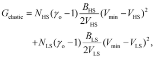 | (8) |
 | (9) |
 | (10) |
 | (11) |
The total elastic interaction energy of the bulk system is then written as:
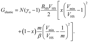 | (12) |
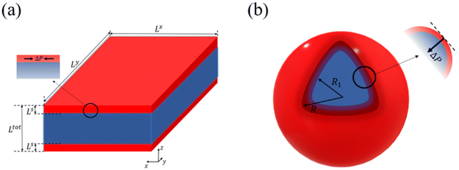
Let us now turn our attention to the surface thermodynamics. Surface Gibbs energy Gsurface is defined as the summation of two contributions: the surface energy Gse and the surface stress Gss. The surface energy corresponds to the work per unit area involved in the formation of a surface, while the surface stress is associated with the reversible work per unit area needed to elastically stretch a pre-existing surface. Accordingly, the total surface energy and the work against surface stress in a flat thin film (Fig. 1(a)) with a surface area A can be calculated by:
| Gse = γA, | (13) |
| Gss = σdA, | (14) |
It should be noted that the surface stress is considered to be isotropic and independent of the strain in this study.
Let a0 be the lattice parameter of the material. Na and Nb are defined as the number of molecules in the surface and in the core, respectively. The contribution of the surface energy and surface stress to the Gibbs free energy of the film is then written as:
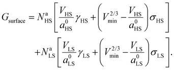 | (15) |
On the other hand, in the case of a spherical particle (Fig. 1(b)) of volume V and surface area A, according to the Laplace–Young equation,37 the difference of internal and external pressure (ΔP) is expressed as:
 | (16) |
In this case, the work against surface stress (Gss) is derived from the pressure difference:
 | (17) |
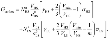
Then the total contribution of the surface becomes:
 | (18) |
In eqn (18),  stands for the total surface area of the system.
First, we calculate the above contributions in the case of a flat thin film whose dimensions along the x and y directions are Lx and Ly, respectively. The film consists of a bulk-like core of thickness Ltot and two surfaces of identical thickness Ls along the z direction, as shown in Fig. 1(a). Under the consideration that LxLy ≫ Ltot and that all the molecules in the system are in the HS state, the number of molecules in the core (Nb) and in the shell (Ns) is given by:
 | (19) |
 | (20) |
Assuming as a first approximation that the shell consists of a monolayer, the number of molecules at the surface Na is equal to the number of molecules in the shell Ns. Accordingly, NaHS and NaLS in eqn (15) can be calculated through:
 | (21) |
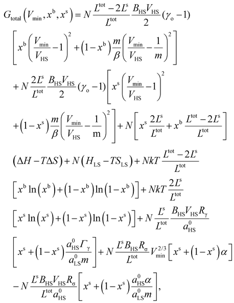
 | (22) |
 | (23) |
 , the LS-to-HS surface stress ratio
  , and two characteristic lengths
  and
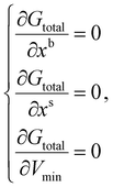
and  . The exact stationary solution of the model can be obtained by solving the following non-linear system of equations:
 | (24) |
A similar set of equations has been also derived for a spherical core–shell model that consists of a bulk-like core of radius R1 and a shell of thickness (R − R1) as shown in Fig. 1(b). The details of the algebra are given in the ESI.†
As the sets of equations derived from the different models are highly non-linear, it seems difficult to solve them analytically. The numerical solutions are obtained at given temperatures T by means of the vpasolve solver in MATLAB (MathWorks® Inc. Natick, MA). It should be mentioned that due to the strong coupling between different physical properties combined to the high nonlinearity of the equation set, investigating the effects of different parameters on the SCO behavior turns out to be a challenging task. Thus, in the next sections, we will first explore the effects of surface energy (resp. surface stress) on the SCO properties in a 5 nm thin film of the SCO compound [Fe(pyrazine)][Ni(CN)4] in the case where σHS = σLS = 0 (resp. γHS = γLS = 0). Then, the values of surface energy and surface stress will be fixed to investigate the size reduction effects.
3. Results and discussion
A. Bulk material
For our investigation we have selected the Hoffmann-like clathrate compound [Fe(pyrazine)][Ni(CN)4], whose certain physical properties are summarized in Table 1. This choice was motivated by the fact that the different properties of this compound are relatively well documented thanks to the works reported in ref. 38–40. Let us note also that the high symmetry of the lattice in this compound (P4/mmm) allows us to neglect the effects of anisotropy in a first assumption. The isotropic bulk modulus B can be obtained from the isotropic Young's modulus Y as:39 | (25) |
We first calculate the temperature dependence of the HS fraction for the bulk material, i.e., for Ltot → +∞ (R → +∞). As displayed in Fig. 2(a), if we neglect the elastic interactions between the molecules (Gelastic = 0), a gradual spin conversion is observed, as expected. However, if we include the intermolecular elastic interaction term, a sharp increase of the HS fraction is observed at T½↑ = 303 K in the heating mode, whereas a sharp drop of the HS fraction is found at T½↓ = 281 K in the cooling process (Fig. 2(a)), giving rise to a thermal hysteresis loop whose width (ΔT ≈ 22 K) which is close to the experimentally observed value (ΔT = 25 K).38 The transition temperature in the heating process is about 13 K higher than that of the gradual transition (290 K). This difference arises due to the existence of an extra elastic energy barrier associated with the inter-molecular interactions as shown in Fig. 2(b). It is also interesting to notice in Fig. 2 that the residual fraction of molecules in the LS state at high temperature decreases from ∼16% to ∼3% with the participation of the inter-molecular interactions, indicating that the elastic interaction between two molecules tend to stabilize the HS state at high temperature.
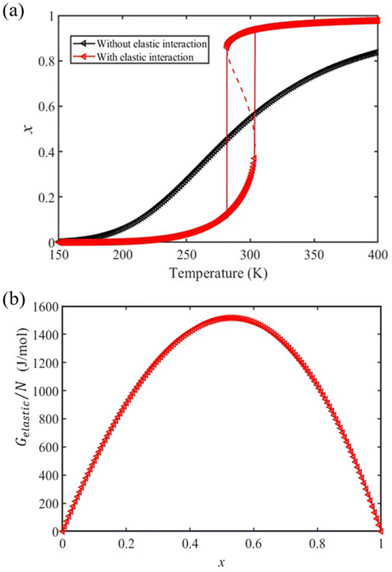 | ||
| Fig. 2 (a) Calculated temperature dependence of the HS fraction in the bulk material (red triangles) using the input physical quantities reported in Table 1. The gradual conversion curve in black, corresponding to the case where no elastic interaction is considered, is drawn for comparison. (b) Dependence of the elastic interaction energy density with the HS fraction. | ||
B. Surface energy effect
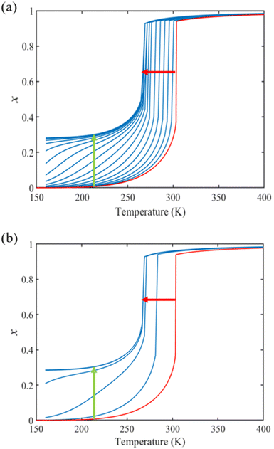
From the simulation of the bulk material, we can conclude that the model is able to reproduce with reasonable accuracy the experimentally observed SCO behavior without using any adjustable, phenomenological parameters. We now turn our attention to the investigation of the influence of surface energy/stress on the SCO properties in finite-size systems. It should be mentioned that the results obtained for a thin film of thickness Ltot = 5 nm and those obtained for a particle of radius R = 5 nm lead to similar conclusions. For this reason, in the following we only show the simulations performed for the Ltot = 5 nm thin film of the [Fe(pyrazine)][Ni(CN)4] compound, while the results obtained with the spherical model are provided in the ESI.†The temperature dependence of the total HS fraction is first calculated for different values of γHS varying from 10 to 190 mJ m−2 with an increment of 10 mJ m−2 under the consideration of σHS = σLS = 0. As two typical examples, the cases of  are displayed in Fig. 3. Only cases such as Γγ > 1 are considered because it is known that the surface energy in the HS state is lower than in the LS state due to a smaller cohesion energy in the HS state.
In both cases, one can notice an increase of the residual HS fraction at low temperature for increasing values of γHS (indicated by green arrows in Fig. 3). Interestingly, this residual HS fraction reaches a maximum value of x ≈ 0.28, which is close to the proportion of the molecules in the shell  . We can thus conclude that the transition temperature of the molecules at the surface is considerably downshifted with the size reduction and, eventually, they remain trapped in the HS state. Furthermore, as indicted by the red arrows in Fig. 3, the spin transition in the core also shifts gradually to lower temperatures as γHS increases. In fact, the molecules in the shell, which undergo SCO at lower temperatures, have the effect of stabilizing the HS state in the core of the system due to the existence of elastic inter-molecular interactions between the molecules in the shell and the core. Indeed, there is a minimum value of the equilibrium temperature at ∼266 K with the increase of γHS since the effect of elastic interactions between the shell and the core becomes maximum when all the molecules in the shell are blocked in the HS state.
As it can be seen in Fig. 3(b) for Γγ = 2.4, the molecules in the shell completely switch into the HS state for lower values of γHS in comparison to the case Γγ = 1.4, which signifies that the surface effects arise by increasing either the absolute value of the surface energy or the ratio of LS-to-HS surface energies. Indeed, both effects give rise to an increase of the surface energy difference between the LS and HS states (γLS − γHS). This quantity can thus be considered as a primary driving force of finite size induced effects on the SCO phenomenon.24
C. Surface stress effect
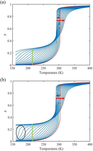
Different from the surface energy which is always positive, the surface stress can be either positive (tensile stress) or negative (compressive stress), depending on the variation of distances between atoms at the surface.25–27 To avoid any ad hoc hypothesis, we have thus computed the thermally induced spin-transition curves of a 5 nm thin film for different values of σHS varying either from +10 to +410 mJ m−2 (assuming tensile stresses) or from −410 to −10 mJ m−2 (assuming compressive stresses) with an increment of 20 mJ m−2. On the other hand, as the denser LS phase is expected to be stiffer than the HS phase, one can assume that |σLS| > |σHS|. To avoid the implication of too many parameters in this study, two ratios of LS-to-HS surface stress ( ) are considered while the surface energies in both spin states are set to γHS = γLS = 0.
Fig. 4(a) and (b) summarize the temperature dependence of the HS fraction calculated through positive surface stress in the cases of  , respectively. As indicating by the green arrow in Fig. 4(a), increasing the value of σHS leads to a rise of the residual HS fraction at low temperature – similar to the effect of an increasing value of γHS discussed above. Again, the highest residual HS fraction is found to be x = ∼0.28 denoting that the equilibrium temperature of the molecules in the shell is shifted downwards when increasing σHS until a complete blocking of the shell in the HS state is observed. The existence of a non-zero surface stress during the spin-state switching exerts a stress/pressure to the surface of the material. When considering a positive surface stress, the two surfaces of the thin film are under tensile stress, which favors the HS state, leading to a downshift of the transition temperature of the molecules in the shell (surface).
On the other hand, the surface stress must be balanced by a volume stress in the bulk-like core since there should be no net force in the system.41,42 As a result, an obvious change of the SCO behavior of the bulk-like core can be observed. Indeed, as shown by the red arrows in Fig. 4(a), the equilibrium temperature first downshifts when increasing σHS until it reaches its lowest value (∼290 K). Similar to the surface energy effect, this downshift can be attributed to the elastic intermolecular interaction between the HS molecules in the shell and the LS molecules in the bulk-like core. However, this minimum of the equilibrium temperature (∼290 K) remains higher when compared to the case of the surface energy effect (∼266 K) because the molecules in the bulk-like core are under compression, which stabilizes the LS state. In other words, the surface stress induces two competing effects, favoring either the HS or the LS state. However, the stabilization of the HS state is limited by the thickness of the shell. As a result, when the molecules in the shell are fully blocked in the HS state, a further increase of σHS will give rise solely to an increase of the compressive stress in the bulk-like core, which is manifested in Fig. 4 by a clear upshift of the equilibrium temperature. As shown in Fig. 4(b), similar features can be observed in the case of  , i.e., a downshift of the equilibrium temperature as well as a growing of the residual HS fraction at low temperature as σHS increases. Interestingly, an abrupt spin transition could be found in the shell as highlighted by the black circles. On the contrary, as σHS increases, the SCO behavior of the bulk-like core changes from abrupt to gradual transition. Such enhancement/loss of the cooperativity in different regions of the SCO nano-object induced by tensile/compressive pressure is well known in the SCO literature, including both theoretical studies as well as experimental observations performed under high pressure.43–48
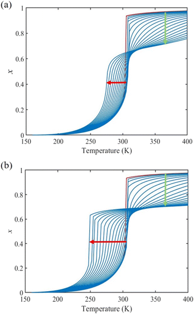
Fig. 5(a) displays the thermally induced spin transition for negative (compressive) values of the surface stress in the case of  . Globally, the observed effects “mirror” the case of tensile surface stress, though some differences occur as well.
On one hand, as indicated by the green arrow in Fig. 5, a progressive increase of the residual LS fraction at high temperatures can be observed with the increase of the magnitude of σHS. The residual LS fraction at high temperature peaks at a value of ∼0.2, indicating that the molecules in the shell are blocked by the compressive stress (i.e. their thermal transition is shifted to high temperatures).
On the other hand, to ensure the mechanical equilibrium, a tensile stress exists in the bulk-like core, balancing the surface stress. Similar to the case of positive surface stress, two competing effects can be noticed. The tensile stress in the core tends to stabilize the HS state, whereas the elastic interaction with the shell tends to stabilize the LS state. As shown in Fig. 5(a), first a slight increase (∼3 K) of the equilibrium temperature can be seen when the magnitude of σHS is small. Though the blocked LS molecules in the shell tend to stabilize the LS state in the bulk-like core via elastic intermolecular interactions, the tensile stress, which favors the HS state, becomes quickly dominant as σHS increases, leading to an obvious downshift of the equilibrium temperature (shown by the red arrow). It is thus not surprising to see from Fig. 5(b) that a clear abrupt spin-state switching appears in the bulk-like core when the surface compressive stress is large (<−310 mJ m−2). It is interesting to remark that this type of surface stress effect might thus contribute to the re-appearance of a thermal hysteresis loop at reduced sizes, as reported in ultra-small nanoparticles of the compound [Fe(pyrazine)][Ni(CN)4].49 In previous reports, this phenomenon was attributed to the modification of the surface elastic properties and/or particle–matrix interactions,24,50 but the present work indicates that the existence of a negative (compressive) surface stress can also give rise to such effects.
To summarize our findings on the surface energy/stress effects, it is interesting to remark that the incomplete spin transitions experimentally observed in nanoscale objects may be attributed to the double effect of the surface energy and the surface stress. The contribution of surface energy is associated with both electronic and structural surface relaxations, which has been discussed in previous studies.15,16,24,51 On the other hand, the contribution of surface stress is related to the mechanical equilibrium of the system, which is the result of competing forces acting at the free surface and in the bulk-like core during the spin transition. In other words, a controlled modification of the surface/interface elastic properties or of the chemical nature of the surface could potentially allow one to tune the SCO properties at the nano-scale. The present work provides some general guidelines for this endeavor.
D. Size effects
To our best knowledge, there is no reported value of the surface energy or surface stress of any SCO material. In the interim, we used molecular dynamics (MD) simulations, based on a recently built force field, to calculate the surface energies of the compound [Fe(pyrazine)][Ni(CN)4] in the two spin states.33,52 (see the ESI† for more details of the MD calculation.) Through these calculations, the obtained surface energies in the LS and HS states are ELSsur = 49 mJ m−2 and EHSsur = 21 mJ m−2, respectively. It is interesting to note that these numerical values are comparable with surface energies of organic and polymeric materials, such as polytetrafluoroethylene, poly(methyl methacrylate) and poly(vinyl chloride), whose reported values of γ range between ca. 20 and 40 mJ m−2 at room temperature.53 Considering the link between surface stress and elasticity, the ratio is set to 1.43, to match the reported ratio of the Young's moduli of [Fe(pyrazine)][Ni(CN)4] in the LS and HS states
  .39 Moreover, since the size reduction usually leads to a downshift of the equilibrium temperature and the appearance of a residual HS fraction at low temperatures in the compound [Fe(pyrazine)][Ni(CN)4],49,54 the surface stress is assumed to be positive in the present work. For most solids, the surface stress is generally of the same order of magnitude as the surface energy,27–29 so that the surface stress in the HS state is finally fixed arbitrarily to σHS = 100 mJ m−2 for further calculations.
The calculated temperature dependence of the total HS fraction is shown in Fig. 6 in the case of the thin-film model of different thicknesses whereas results obtained with the spherical model are provided in the ESI.† On the whole, an increase of the residual HS fraction as well as a downshift of the equilibrium temperature are clearly observed with the size reduction, which is in qualitative agreement with experimental observations on different SCO compounds.49,54–59 In particular, a gradual spin conversion with a transition temperature of ∼266 K as well as a residual HS fraction of x = 0.4 at 200 K was derived from the calculation for a 5-layer (∼3.5 nm) thin film (Fig. 6). This result can be compared with a recent experimental study using variable-temperature Raman spectroscopy, which revealed a gradual SCO curve centered at ∼260 K accompanied by a residual HS fraction of ∼0.45 at 200 K for a 5-layer thick film of [Fe(pyrazine)][Ni(CN)4].60 Such good agreement between the results from our model and the experimental observations is promising, but it is important to remind that we lack extensive experimental data both on size-reduction effects and on the surface thermodynamical parameters for [Fe(pyrazine)][Ni(CN)4] and, in general, for any SCO compounds. To validate the model and establish a real predictive capability, dedicated experimental approaches will therefore need to be developed.
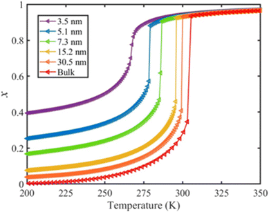 | ||
| Fig. 6 Calculated temperature dependence of the total HS fraction (heating mode) for different film thicknesses of the compound [Fe(pyrazine)][Ni(CN)4]. | ||
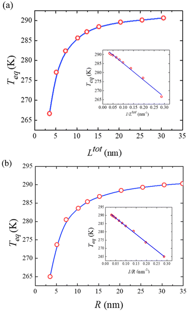
To conclude this study, Fig. 7(a) displays the computed equilibrium temperature given by:
 | (26) |
 , from which a clear reciprocal relationship can be established between these two quantities:
 | (27) |
Moreover, Fig. 7(b) displays the computed equilibrium temperature as a function of the radius of the [Fe(pyrazine)][Ni(CN)4] spherical particle. Similar to the thin-film case, Teq shows algebraic decay as the size of the particle is reduced. Meanwhile, the calculated equilibrium temperature of the spherical particle also follows a clear reciprocal relationship with respect to the radius (see the insert of Fig. 7(b)). It should be noted that the  (
( in the case of the spherical nanoparticle) dependence of the equilibrium temperature with the thickness (radius) is a common finding for various nanoscale materials, which can be ubiquitously linked to the variation of the surface-to-volume ratio of the object (e.g.
 in the case of thin film). In particular, this relationship could be also derived from different atomistic/thermodynamic studies dealing with finite-size effects in SCO objects.13,14,24
4. Conclusions
We developed a nano-thermodynamic core–shell model describing the effects of surface energy and surface stress on the SCO properties of thin films and spherical particles. The study of the surface energy effect shows a decrease of the equilibrium temperature as well as the occurrence of a residual HS fraction at low temperatures, which agrees well with previous experimental reports. A positive (resp. negative) surface stress give rise to a residual HS (resp. LS) fraction at low (resp. high) temperature, due to the pressure acting on the shell (surface layer). Remarkably, both positive and negative values of surface stress can lead to either an upshift or a downshift of the equilibrium temperature, depending on their magnitude. This behavior is the result of a competition between elastic inter-molecular interactions between the core and the shell and the build-up of internal pressure in the core induced by the surface stress. Besides, such a competition could entail a change of the cooperativity of the system with size reduction, which may further lead to the emergence of multistep transitions and the re-opening of hysteresis loops at ultra-small sizes. The present model reveals that the appearance of incomplete spin transitions and the shift of the transition temperature at the nano-scale may be attributed to the double contribution of the surface energy (from an energetic point of view) and the surface stress (from a mechanical point of view). With these general conclusions in hand, we conducted a more specific investigation of the size-reduction effects on nanometric films of the SCO compound [Fe(pyrazine)][Ni(CN)4]. To this aim, we first calculated the surface energies through MD simulations and made a rough estimation of the surface stress in the two spin states. At this stage, the latter quantity thus appears as an adjustable parameter in our model. As such, the good agreement between our computational results and the experimental observations in the literature should not be over interpreted. Nevertheless, the model is already able to grasp the experimentally observed SCO behaviors at the nano-scale and provides physical insights to their origin. The very important point to be stressed is that, potentially, each input parameter of the present model is experimentally accessible. This fact combined with the simple numerical procedure, provides a powerful tool to analyze and even predict SCO behaviors of different compounds at finite sizes.Conflicts of interest
There are no conflicts to declare.Acknowledgements
This project has received funding from the European Research Council (ERC) under the European Union's Horizon 2020 research and innovation programme (grant agreement no.101019522). SM thanks the China Scholarship Council for a PhD grant.References
- P. Gütlich, A. Hauser and H. Spiering, Angew. Chem., Int. Ed. Engl., 1994, 33, 2024–2054 CrossRef.
- A. Bousseksou, G. Molnár, L. Salmon and W. Nicolazzi, Chem. Soc. Rev., 2011, 40, 3313–3335 RSC.
- Spin crossover in transition metal compounds I-III, in Topics in Current Chemistry, ed. P. Gütlich and H. A. Goodwin, Springer, Berlin, 2004, vol. 233–235 Search PubMed.
- Spin-crossover materials: properties and applications, ed. M. A. Halcrow, Wiley, Chichester, UK, 2013 Search PubMed.
- P. Guionneau, Dalton Trans., 2014, 43, 382–393 RSC.
- G. Molnár, S. Rat, L. Salmon, W. Nicolazzi and A. Bousseksou, Adv. Mater., 2018, 30, 1703862 CrossRef PubMed.
- O. Kahn, J. Kröber and C. Jay, Adv. Mater., 1992, 4, 718–728 CrossRef CAS.
- K. S. Kumar and M. Ruben, Coord. Chem. Rev., 2017, 346, 176–205 CrossRef.
- L. Salmon and L. Catala, C. R. Chim., 2018, 21, 1230–1269 CrossRef CAS.
- T. Mallah and M. Cavallini, C. R. Chim., 2018, 21, 1270–1286 CrossRef CAS.
- M. Mikolasek, G. Félix, W. Nicolazzi, G. Molnár, L. Salmon and A. Bousseksou, New J. Chem., 2014, 38, 1834–1839 RSC.
- T. Kawamoto and S. Abe, Chem. Commun., 2005, 31, 3933–3935 RSC.
- A. Muraoka, K. Boukheddaden, J. Linares and F. Varret, Phys. Rev. B: Condens. Matter Mater. Phys., 2011, 84, 054119 CrossRef.
- A. Slimani, K. Boukheddaden and K. Yamashita, Phys. Rev. B: Condens. Matter Mater. Phys., 2014, 89, 214109 CrossRef.
- M. Mikolasek, W. Nicolazzi, F. Terki, G. Molnár and A. Bousseksou, Chem. Phys. Lett., 2017, 678, 107–111 CrossRef CAS.
- M. Mikolasek, W. Nicolazzi, F. Terki, G. Molnár and A. Bousseksou, Phys. Chem. Chem. Phys., 2017, 19, 12276–12281 RSC.
- A. Slimani, H. Khemakhem and K. Boukheddaden, Phys. Rev. B, 2017, 95, 174104 CrossRef.
- A. Railean, M. Kelai, A. Bellec, V. Repain, M.-L. Boillot, T. Mallah, L. Stoleriu and C. Enachescu, Phys. Rev. B, 2023, 107, 014304 CrossRef CAS.
- L. Stoleriu, P. Chakraborty, A. Hauser, A. Stancu and C. Enachescu, Phys. Rev. B: Condens. Matter Mater. Phys., 2011, 84, 134102 CrossRef.
- H. Oubouchou, A. Slimani and K. Boukheddaden, Phys. Rev. B: Condens. Matter Mater. Phys., 2013, 87, 104104 CrossRef.
- G. Félix, M. Mikolasek, G. Molnár, W. Nicolazzi and A. Bousseksou, Chem. Phys. Lett., 2014, 607, 10–14 CrossRef.
- T. Delgado, C. Enachescu, A. Tissot, L. Guénée, A. Hauser and C. Besnard, Phys. Chem. Chem. Phys., 2018, 20, 12493–12502 RSC.
- C. Enachescu, R. Tanasa, A. Stancu, A. Tissot, J. Laisney and M.-L. Boillot, Appl. Phys. Lett., 2016, 109, 031908 CrossRef.
- G. Félix, W. Nicolazzi, L. Salmon, G. Molnár, M. Perrier, G. Maurin, J. Larionova, J. Long, Y. Guari and A. Bousseksou, Phys. Rev. Lett., 2013, 110, 235701 CrossRef PubMed.
- P. Müller, A. Saùl and F. Leroy, Adv. Nat. Sci.: Nanosci. Nanotechnol., 2013, 5, 013002 Search PubMed.
- P. Müller and A. Saúl, Surf. Sci. Rep., 2004, 54, 157–258 CrossRef.
- R. C. Cammarata and K. Sieradzki, Annu. Rev. Mater. Sci., 1994, 24, 215–234 CrossRef CAS.
- Q. Jiang, J. Li and M. Zhao, J. Phys. Chem. B, 2003, 107, 13769–13771 CrossRef CAS.
- C. Yang, S. Li and J. Armellin, J. Phys. Chem. C, 2007, 111, 17512–17515 CrossRef CAS.
- S. Sood and P. Gouma, J. Am. Ceram. Soc., 2013, 96, 351–354 CrossRef CAS.
- H. Zhang and J. F. Banfield, J. Mater. Chem., 1998, 8, 2073–2076 RSC.
- L. F. Drummy and D. C. Martin, Adv. Mater., 2005, 17, 903–907 CrossRef CAS.
- A. Fahs, S. Mi, W. Nicolazzi, G. Molnár and A. Bousseksou, Adv. Phys. Res., 2023, 2, 2200055 CrossRef.
- W. Nicolazzi and A. Bousseksou, C. R. Chim., 2018, 21, 1060–1074 CrossRef CAS.
- H. Spiering, K. Boukheddaden, J. Linares and F. Varret, Phys. Rev. B: Condens. Matter Mater. Phys., 2004, 70, 184106 CrossRef.
- J. Eshelby, Solid State Phys., 1956, 3, 79–144 CAS.
- J. Weissmüller and J. W. Cahn, Acta Mater., 1997, 45, 1899–1906 CrossRef.
- V. Niel, J. M. Martinez-Agudo, M. C. Munoz, A. B. Gaspar and J. A. Real, Inorg. Chem., 2001, 40, 3838–3839 CrossRef CAS PubMed.
- G. Félix, M. Mikolasek, H. Peng, W. Nicolazzi, G. Molnár, A. I. Chumakov, L. Salmon and A. Bousseksou, Phys. Rev. B: Condens. Matter Mater. Phys., 2015, 91, 024422 CrossRef.
- P. D. Southon, L. Liu, E. A. Fellows, D. J. Price, G. J. Halder, K. W. Chapman, B. Moubaraki, K. S. Murray, J.-F. Létard and C. J. Kepert, J. Am. Chem. Soc., 2009, 131, 10998–11009 CrossRef CAS PubMed.
- F. H. Streitz, R. C. Cammarata and K. Sieradzki, Phys. Rev. B: Condens. Matter Mater. Phys., 1994, 49, 10699 CrossRef CAS PubMed.
- R. Shuttleworth, Proc. Phys. Soc., London, Sect. A, 1950, 63, 444 CrossRef.
- Y. Konishi, H. Tokoro, M. Nishino and S. Miyashita, Phys. Rev. Lett., 2008, 100, 067206 CrossRef PubMed.
- P. Gütlich, A. B. Gaspar, V. Ksenofontov and Y. Garcia, J. Phys.: Condens. Matter, 2004, 16, S1087 CrossRef.
- A. B. Gaspar, G. Molnár, A. Rotaru and H. J. Shepherd, C. R. Chim., 2018, 21, 1095–1120 CrossRef CAS.
- A. Rotaru, J. Linares, F. Varret, E. Codjovi, A. Slimani, R. Tanasa, C. Enachescu, A. Stancu and J. Haasnoot, Phys. Rev. B: Condens. Matter Mater. Phys., 2011, 83, 224107 CrossRef.
- R. Li, G. Levchenko, F. J. Valverde-Muñoz, A. B. Gaspar, V. V. Ivashko, Q. Li, B. Liu, M. Yuan, H. Fylymonov and J. A. Real, Inorg. Chem., 2021, 60, 16016–16028 CrossRef CAS PubMed.
- R. Li, G. Levchenko, F. J. Valverde-Muñoz, A. B. Gaspar, V. V. Ivashko, Q. Li, W. Xu, H. Fylymonov, B. Liu and J. A. Real, J. Mater. Chem. C, 2022, 10, 11388–11400 RSC.
- H. Peng, S. Tricard, G. Félix, G. Molnár, W. Nicolazzi, L. Salmon and A. Bousseksou, Angew. Chem., 2014, 126, 11074–11078 CrossRef.
- M. Mikolasek, G. Félix, H. Peng, S. Rat, F. Terki, A. I. Chumakov, L. Salmon, G. Molnár, W. Nicolazzi and A. Bousseksou, Phys. Rev. B, 2017, 96, 035426 CrossRef.
- G. Félix, W. Nicolazzi, M. Mikolasek, G. Molnár and A. Bousseksou, Phys. Chem. Chem. Phys., 2014, 16, 7358–7367 RSC.
- S. Mi, A. Fahs, G. Molnár, W. Nicolazzi and A. Bousseksou, Chem. Phys. Lett., 2023, 811, 140232 CrossRef CAS.
- D. K. Owens and R. Wendt, J. Appl. Polym. Sci., 1969, 13, 1741–1747 CrossRef CAS.
- F. Volatron, L. Catala, E. Rivière, A. Gloter, O. Stéphan and T. Mallah, Inorg. Chem., 2008, 47, 6584–6586 CrossRef CAS PubMed.
- J. R. Galán-Mascarós, E. Coronado, A. Forment-Aliaga, M. Monrabal-Capilla, E. Pinilla-Cienfuegos and M. Ceolin, Inorg. Chem., 2010, 49, 5706–5714 CrossRef PubMed.
- J. Larionova, L. Salmon, Y. Guari, A. Tokarev, K. Molvinger, G. Molnár and A. Bousseksou, Angew. Chem., Int. Ed., 2008, 47, 8236–8240 CrossRef CAS PubMed.
- M. Kelai, A. Tauzin, A. Railean, V. Repain, J. Lagoute, Y. Girard, S. Rousset, E. Otero, T. Mallah and M.-L. Boillot, J. Phys. Chem. Lett., 2023, 14, 1949–1954 CrossRef CAS PubMed.
- M. Kelai, V. Repain, A. Tauzin, W. Li, Y. Girard, J. Lagoute, S. Rousset, E. Otero, P. Sainctavit and M.-A. Arrio, J. Phys. Chem. Lett., 2021, 12, 6152–6158 CrossRef CAS PubMed.
- S. Sakaida, K. Otsubo, M. Maesato and H. Kitagawa, Inorg. Chem., 2020, 59, 16819–16823 CrossRef CAS PubMed.
- T. Haraguchi, K. Otsubo, O. Sakata, A. Fujiwara and H. Kitagawa, J. Am. Chem. Soc., 2021, 143, 16128–16135 CrossRef CAS PubMed.
Footnote |
| † Electronic supplementary information (ESI) available. See DOI: https://doi.org/10.1039/d4nr00477a |
| This journal is © The Royal Society of Chemistry 2024 |

